1. STALL
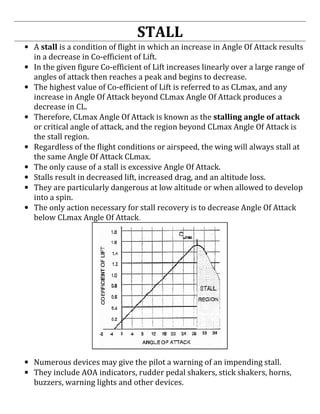
• A stall is a condition of flight in which an increase in Angle Of Attack results
in a decrease in Co-efficient of Lift.
• In the given figure Co-efficient of Lift increases linearly over a large range of
angles of attack then reaches a peak and begins to decrease.
• The highest value of Co-efficient of Lift is referred to as CLmax, and any
increase in Angle Of Attack beyond CLmax Angle Of Attack produces a
decrease in CL.
• Therefore, CLmax Angle Of Attack is known as the stalling angle of attack
or critical angle of attack, and the region beyond CLmax Angle Of Attack is
the stall region.
• Regardless of the flight conditions or airspeed, the wing will always stall at
the same Angle Of Attack CLmax.
• The only cause of a stall is excessive Angle Of Attack.
• Stalls result in decreased lift, increased drag, and an altitude loss.
• They are particularly dangerous at low altitude or when allowed to develop
into a spin.
• The only action necessary for stall recovery is to decrease Angle Of Attack
below CLmax Angle Of Attack.
• Numerous devices may give the pilot a warning of an impending stall.
• They include AOA indicators, rudder pedal shakers, stick shakers, horns,
buzzers, warning lights and other devices.
2. • Some of these devices receive their input from attitude gyros,
accelerometers, or flight data computers, but most receive input from an
AOA probe.
• The AOA probe is mounted on the fuselage or wing and has a transmitter
vane that remains aligned with the relative wind.
• The vane transmits the angle of attack of the relative wind to a cockpit AOA
indicator or is used to activate other stall warning devices.
• Some of the airplanes have standardized AOA indicators graduated in
arbitrary units of angle of attack, or graduated from zero to 100 percent.
• Stalls at idle in a clean configuration are characterized by a nose down pitch
with a slight rolling tendency at near full aft stick.
• The effect of the landing gear on stalls is negligible, but extending the flaps
will aggravate the stall characteristics by increasing the rolling tendency.
• Increased power will degrade the stall characteristics by increasing nose up
stall attitude, increasing buffeting and increasing roll tendency.
AEROFOIL CONTAMINATION
• Aircraft icing in flight is usually classified as being either structural icing or
induction icing.
• Structural icing refers to ice forming on aircraft and components while
induction icing refers to ice formation in the engine induction system.
STRUCTURAL ICING
• Ice forms on aircraft structure and surfaces when super cooled water
droplets impinge on them and freeze.
• Small and/or narrow objects are the best collectors of water droplets and
ice up rapidly.
INDUCTION ICING
• In turbo jet aircraft, air is drawn into the engine creates an area of reduced
pressure at the inlet, which lowers the temperature below that of the
surrounding air.
• In marginal icing condition, this reduction in temperature may be sufficient
to cause ice to form on the engine inlet, disrupting airflow into the engine.
3. LEVELS OF INTENSITY
TRACE
• Ice becomes perceptible.
• Rate of accumulation is slightly greater than the rate of sublimation.
• It is not dangerous even though de-icing/anti-icing equipment is not used,
unless encountered for an extended period of time. (say over one hour)
LIGHT
• The rate of accumulation may create a problem if flight is prolonged in this
environment.(say over one hour)
• Occasional use of de-icing/anti-icing equipment removes/prevents ice
accumulation.
• It does not present a problem if de-icing/anti-icing equipment is used.
MODERATE
• The rate of accumulation is such that even short encounters become
potentially dangerous and use of de-icing/anti-icing equipment is
necessary. Diversion of flight is necessary.
SEVERE
• The rate of accumulation is such that the de-icing/anti-icing equipment fails
to reduce or control the hazard. Diversion of flight is necessary.
EFFECTS OF ICING ON AIRCRAFT
• The lift characteristics of the lift producing surfaces are destroyed.
• It affects the performance of the aircraft.
• The efficiency of the aircraft is decreased.
• It increases the weight of the aircraft.
• It increases the drag and reduces the lift.
• It causes destructive vibrations.
• It hampers true instrument readings.
• Radio reception and engine performance is affected.
• It affects the clear visibility of the pilot.
CLASSIFICATION OF ICE FORMED ON AIRCRAFT STRUCTURE
There are four main types of icing that usually form on an aircraft structure. They
are: (1) Frost/Hoar frost (2) Rime ice (3) Clear ice or Glaze ice and (4) Mixed ice.
• The type of ice formed on an aircraft structure mainly depends on different
meteorological conditions, which are dependant on temperature and
precipitation.
4. FROST/HOAR FROST
• Ice crystals formed by sublimation when water vapour freezes on the
ground or any other exposed object, whose temperature is at or below zero
degree centigrade forming a white crystalline structure.
• This does not form a heavy blanket on the aircraft structure.
• Frost roughens the surface of the aircraft and is similar to sticking sheets of
coarse emery paper all over the skin.
RIME ICE
• Rime ice is the term given to a rough opaque white structure.
• Rime ice can form at ground level or at altitude.
• In flight, rime ice forms on the leading edge of an aircraft when it flies
through a low density cloud of small super cooled water droplets.
• Low temperatures, lesser amount of liquid water, low velocities and small
droplets favour formation of rime ice.
• Rime ice usually forms on areas such as leading edge of wings or struts.
CLEAR ICE (GLAZE ICE)
• Glaze ice is also known as clear ice or rain ice.
• Glaze ice forms a transparent air free sheet on an aircraft structure.
• Glaze ice can be formed even when the aircraft is on the ground by freezing
rain water.
• Glaze ice can be formed when the aircraft flies into a dense cloud of small
super cooled water droplets.
• Glaze ice is denser, harder and sometimes more transparent than rime ice.
• Temperature close to the freezing point, large amounts of liquid water, high
aircraft velocities and large droplets are conducive to formation of clear ice.
• Glaze ice is most dangerous because it is clear, hard to see and can change
the shape of the aerofoil.
MIXED ICE
• Mixed ice is a mixture of Rime ice and glaze ice.
• Mixed ice has the bad characteristics of both Rime ice and glaze ice.
• Mixed ice forms rapidly.
• Ice particles become embedded in clear ice, building a very rough
accumulation.
5. FORCES ACTING ON AN AIRCRAFT
THE FOUR FORCES (IN STEADY LEVEL FLIGHT-CRUISE)
• When a well-trimmed aircraft is cruising (i.e. flying at a constant speed, and
maintaining a constant heading and a constant altitude) in non-turbulent
air, there are two sets, or couples, of basic forces acting on it.
The two forces in each couple are equal and approximately opposite to each
other otherwise the aircraft would not continue to fly straight and level at a
constant speed; i.e. the aircraft is in a state of equilibrium where all forces
balance each other out so there is no change in motion.
• The couple that acts vertically is the lift, generated by the energy of the
airflow past the wings and acting upward, and the weight acting downward.
So, being equal and approximately opposite, the lifting force being
generated must exactly match the total weight of the aircraft.
• The couple that acts horizontally is the thrust, generated by the engine-
driven propeller, and the air resistance, caused by the friction and pressure
of the airflow, or drag, trying to slow the moving aircraft. The thrust, acting
forward along the flight path, exactly equals the drag.
• The thrust provides energy to the aircraft and the drag dissipates that same
energy into the atmosphere. The forces are not all equal to each other. In
fact, an aircraft in cruising flight might generate ten times more lift than
thrust.
• When all forces are in equilibrium a moving aircraft will tend to keep
moving along the same flight path at the same speed- whether it is flying
straight and level, descending or climbing- until an applied force or a
displacement force changes that state of motion. For instance, if the pilot
6. opens the engine throttle fully, and maintains level flight, the thrust force is
initially greater than drag and the aircraft accelerates. However, as the
speed of airflow over the aircraft increases, the air resistance also increases
and the aircraft will soon reach the speed - its maximum- where the forces
are again balanced.
THE FOUR FORCES (IN STEADY LEVEL FLIGHT-SLOWER THAN CRUISE)
• At a constant cruise speed, maintaining straight-and-level flight, the force of
thrust and drag act opposite to each other and parallel to the flight path.
• These opposing forces are equal in magnitude. Also, the force of lift is equal
in magnitude to the force of weight.
• While maintaining straight-and-level flight at constant airspeeds slower
than cruise, the opposing forces must still be equal in magnitude, but some
of these forces are separated into components.
• In this flight condition, the actual thrust no longer acts parallel and opposite
to the flight path and drag.
• Actual thrust is inclined upward as illustrated in figure given above.
• Note that now thrust has two components; one acting perpendicular to the
flight path in the direction of lift, while the other acts along the flight path.
• Because the actual thrust is inclined, its magnitude must be greater than
drag if its component of thrust along the flight path is to equal drag.
• Also note that a component of thrust acts 90° to the flight path, and thus
acts in the same direction as wing lift. The given figure also illustrates that
the forces acting upward (wing lift and the component of thrust) equal the
forces acting downward (weight and tail-down force).
7. • Wing loading (wing lift) is actually less at slow speeds than at cruise speeds
because the vertical component of thrust helps support the airplane.
• To summarize, in straight-and-level flight at slow speeds, the actual thrust is
greater than drag, and wing lift is less than at cruise speed.
ARRANGEMENT OF FORCES
• Even though the forces are equal in magnitude and opposite in direction, all
of them cannot be concentrated to act at one point, because their position
are liable to alter and upset the balance.
• Therefore one important thing to be observed is the lift and weight
couplemust always be arranged in one pattern. That is, “Weight always in
front of Lift”. Which will give the aircraft in the event of engine
failure(Thrust failure) a gliding attitude with a slight nose down tendency.
If the lift is in front of the weight, in the above case, the aircraft will stall.
• The next couple to be concentrated is the thrust and the drag. This couple is
to be arranged in such a way that it is used to counteract the nose down
tendency.
• This is possible only when the drag is placed above the thrust. This is the
normal arrangement done on any land planes.
• In one sentence, we can say “ weight forward of lift, drag above the thrust”
In the case of sea planes, where the position of the engines got to be high enough
to keep away from the water, the line of thrust remains above the drag. So, both
the couple gives the aircraft a resultant nose down tendency.
This tendency is counteracted by one of the following ways.
8. 1. By slightly inclining the line of thrust to the horizontal.
2. By providing an inverted camber on the tail plane which provides
downward force.
3. By having an adjustable tail plane, whose angle can be varied in flight.
THE FOUR FORCES (IN A CLIMB)
• The forces acting on an airplane during a climb are illustrated in figure
given above.
• When the airplane is in equilibrium, the weight can be resolved into two
components: one opposing the lift, and the other acting in the same
direction as the drag along the line of the relative wind.
• The requirements for equilibrium are:
o The thrust must equal the sum of the drag and the opposing
component of the weight;
o and the lift must equal its opposing component of the weight.
• The steeper the angle of climb, the shorter becomes the length of the
component of lift, and simultaneously the component of drag becomes
longer.
• Therefore, the lift requirement decreases steadily as the angle of climb
steepens until, in a true vertical climb, if this were possible, the wings
would supply no lift and the thrust would be the only force opposing both
the drag and the weight, which would be acting downward in opposition.
• At a constant power setting, a given rate of climb can be obtained either by
o climbing steeply at a low airspeed or
o by climbing on a shallow path at high airspeed.
• At one extreme, if the airspeed is too low, the induced drag rises to a figure
at which all thrust available is required to overcome the drag and none is
available for climbing.
9. • At the other extreme, if the speed is the maximum obtainable in level flight,
again all the power is being used to overcome the drag and there is no rate
of climb.
• Between these two extremes lies a speed, or a small band of speeds, which
will achieve the best rate of climb.
• The best rate of climb is achieved not at the steepest angle, but at some
combination of moderate angle and optimum airspeed at which the greatest
amount of excess power is available to climb the airplane after the drag has been
balanced.
• The given figure shows that the speed for minimum drag or the lowest
point on the power-required curve, although low, is not the lowest possible
that can be flown without stalling.
• The increase in power required at the lowest speeds (to the left of the
minimum power-required point) is caused by the rapidly rising effects of
induced drag at the lower speeds.
• The propeller driven airplane, under the same set of circumstances and for
a given rated horsepower, suffers a gradual loss of propeller efficiency and,
therefore, a gradual loss of thrust at both ends of its speed range.
• The vertical distance between the power-available and power-required
curves represents the power available for climbing at the particular speed.
• The best climbing airspeed is that at which excess power is at a maximum so
that after expending some power in overcoming drag, the maximum amount of
power remains available for climbing the airplane.
• At the intersection of the curves, all the available power is being used to
overcome drag, leaving none available for climbing.
• Of course at the lower range, excess power for climb soon becomes
available if the angle of attack is reduced to allow an increase in speed.
• The thrust horsepower of piston engines decreases with altitude.
• Even if it is possible to prolong sea-level power to some greater altitude by
supercharging, or some other method of power boosting, the power will
10. inevitably decline when the boosting method employed reaches an altitude
at which it can no longer maintain a set power.
• At higher altitudes, the power available curves are lowered. Since power
required increases with true airspeed (velocity), the thrust horsepower
required to fly at any desired indicated airspeed increases with altitude.
• In summarizing, it is a fallacy to think that an airplane climbs because of
“excess lift.” It does not; the airplane climbs because of power available
over power required.
THE FOUR FORCES (IN A DIVE/GLIDE)
• The forces acting on an airplane in a glide are illustrated in figure given
above.
• For a steady glide with the engine providing no thrust, the lift, drag, and
weight forces must be in equilibrium.
• The illustration shows that weight is balanced by the resultant of lift and
drag.
• The lift vector, acting as it does at right angles to the path of flight, will now
be tilted forward, while the drag vector will be tilted upward and will
continue to act opposite to the path of flight.
• From the illustration, it can be seen that the geometry of the vectors is such
that the angle between the lift vector and the resultant is the same as that
between the glide path and the horizontal.
• This angle (X) between the glide path and the horizontal is called the glide
angle.
• Further examination of this diagram will show that as drag is reduced and
speed increased, the smaller will be the glide angle; therefore, the steepness
of the glide path depends on the ratio of lift to drag.
• When gliding at the angle of attack for best L/D, least drag is experienced,
and the flattest glide will result.
11. • The L/D is a measure of the gliding efficiency or aerodynamic cleanness of
the airplane.
• If the L/D is 11/1, it means that lift is 11 times greater than drag.
• If the gliding airplane is flying at an airspeed just above the stall, it is
operating at maximum angle of attack and therefore, maximum lift.
• This, however, does not produce the best glide angle for maximum glide
distance because the induced drag at this point is high.
• By reducing the angle of attack, the airspeed increases and, although lift is
less at the lower angle of attack, the airplane travels farther per increment
of altitude lost because of greatly reduced drag.
• The increased range can be accomplished up to a point, by decreasing angle
of attack and induced drag. At some point, the best glide angle will be
achieved.
• If airspeed continues to increase, the parasite drag begins to rise sharply
and the airplane will again start losing more altitude per increment of
distance traveled.
• The extreme of this is when the nose is pointed straight down.
• It can be shown that best glide distance is obtained when L/D ratio is at
maximum.
• This optimum condition is determined for each type of airplane and the
speed at which it occurs is used as the recommended best range glide speed
for the airplane.
• It will vary somewhat for different airplane weights, so the airspeed for a
representative operational condition is generally selected.
• If several instances of the optimum glide path were plotted by an observer
on the ground under varying conditions of wind, they would be found to be
inconsistent.
• However, the actual gliding angle of the airplane with respect to the moving
air mass remains unchanged.
• Starting from a given altitude, a glide into the wind at optimum glide
airspeed covers less distance over the ground than a glide downwind.
• Since in both cases the rate of descent is the same, the measured angle as
seen by a round observer is governed only by the groundspeed, being
steeper at the lower groundspeed when gliding into the wind.
• The effect of wind, therefore, is to decrease range when gliding with a
headwind component, and to increase it when gliding downwind.
• The endurance of the glide is unaffected by wind.
12. • Variations in gross weight do not affect the gliding angle provided the
optimum indicated airspeed for each gross weight is used.
• The fully loaded airplane will sink faster but at a greater forward speed, and
although it would reach the ground much quicker, it would have traveled
exactly the same distance as the lighter airplane, and its glide angle would
have been the same.
• An inspection of given figure will show that an increase in the weight factor
is equivalent to adding thrust to the weight component along the glide path.
• This means more speed and, therefore, more lift and drag which lengthen
the resultant vector until the geometric balance of the diagram is restored.
This is done without affecting the gliding angle.
• The higher speed corresponding to the increased weight is provided
automatically by the larger component of weight acting along the glide path,
and this component grows or diminishes in proportion to the weight. Since
the gliding angle is unaffected, range also is unchanged.
• Although range is not affected by changes in weight, endurance decreases
with addition of weight and increases with reduction of weight.
• If two airplanes having the same L/D, but different weights, start a glide
from the same altitude, the heavier airplane, gliding at a higher airspeed,
will cover the distance between the starting point and touch down in a
shorter time.
• Both, however, will cover the same distance. Therefore, the endurance of
the heavier airplane is less.
EFFECT OF WIND ON THE GLIDE
• Starting from a given height a glide into wind at the optimum air speed
covers less distance over the ground than down wind.
• The effect of wind therefore is to decrease the range when gliding with a
head wind component and to increase it when gliding down.
• The endurance of glide is unaffected while the range is affected.
13. EFFECT OF WEIGHT ON THE GLIDE
• Variation in weight does not affect the gliding angle provided that the speed
is adjusted to fit the weight.
• The best “Indicated Air Speed” varies as the square root of the “All Up
Weight”.
• Increase in weight requires an increase in speed and vice versa.
• Since the gliding angle is unaffected by the weight the range is also
unaffected.
EFFECT OF WEIGHT ON ENDURANCE
• Although the range is not affected by changes in weight, the endurance
decreases with the increase in weight and vice-versa.
• If two aircrafts having the same L/D ratio but with different weights start to
glide from the same height and at same time, then the heavier aircraft
gliding at a higher “Indicated Air Speed” will cover the distance between the
starting points and touch down in a shorter time.
• Both will however cover the same distance. Therefore, the endurance of the
heavier aircraft is less.
THE FOUR FORCES (IN A TURN)
• Turning flight is described as changing the direction of the airplane’s flight
path by reorienting the lift vector in the desired direction.
• During a turn, the lift vector is divided into two components, a horizontal
component (LH) and a vertical component (LV).
• The horizontal component of lift, called centripetal force, accelerates the
airplane toward the inside of the turn.
• In straight and level flight (constant altitude, constant direction) total lift is
equal to weight, but in a turn, only the vertical component of the lift vector
opposes weight.
• If the pilot does not increase the total lift vector, the airplane will lose
altitude because weight will be greater than LV.
• The increased lift is normally obtained by increasing the angle of attack, i.e.
pulling back on the stick.
• As the stick moves aft, G forces build up. Increasing the lift produced by the
wings increases the load on the airplane.
• Load factor (n) is the ratio of total lift to the airplane’s weight.
• It is sometimes called Gs since it is the number of times the earth’s
gravitational pull felt by the pilot.
14. • For example, a 3,000 pound airplane in a 60º angle of bank turn must
produce 3,000 pounds of vertical lift to maintain altitude. Therefore, the
wings must produce 6,000 pounds of total lift so the airplane experiences a
load on its wings that is twice the force due to gravity, or 2 Gs. One “G” is
what we experience just sitting or walking.
• In level flight, the force of lift acts opposite to and exactly equal in
magnitude to the force of gravity.
• Gravity tends to pull all bodies to the center of the Earth; therefore, this
force always acts in a vertical plane with respect to the Earth.
• On the other hand, total lift always acts perpendicular to the relative wind,
which for the purposes of this discussion is considered to be the same as
acting perpendicular to the lateral axis of the wind.
• With the wings level, lift acts directly opposite to gravity.
• However, as the airplane is banked, gravity still acts in a vertical plane, but
lift will now act in an inclined plane.
• As illustrated in the given figure, the force of lift can be resolved into two
components, vertical and horizontal.
• During the turn entry, the vertical component of lift still opposes gravity,
and the horizontal component of lift must overcome apparent centrifugal
force.
• Consequently, the total lift must be sufficient to counteract both of these
forces.
• The total resultant lift acts opposite to the total resultant load.
• So long as these opposing forces are equal to each other in magnitude, the
airplane will maintain a constant rate of turn.
• If the pilot moves the controls in such a manner as to change the magnitude
of any of the forces, the airplane will accelerate or decelerate in the
direction of the applied force.
• This will result in changing the rate at which the airplane turns.