1. Electrical Machines II Prof. Krishna Vasudevan, Prof. G. Sridhara Rao, Prof. P. Sasidhara Rao
Indian Institute of Technology Madras
5 Equivalent Circuit
It is often required to make quantitative predictions about the behavior of the induction
machine, under various operating conditions. For this purpose, it is convenient to represent
the machine as an equivalent circuit under sinusoidal steady state operating conditions. Since
the operation is balanced, a single-phase equivalent circuit is sufficient for most purposes.
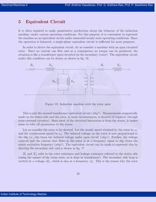
In order to derive the equivalent circuit, let us consider a machine with an open circuited
rotor. Since no current can flow and as a consequence no torque can be produced, the
situation is like a transformer open-circuited on the secondary (rotor). The equivalent circuit
under this condition can be drawn as shown in fig. 16.
Rm Xm
RrXlsRs Xlr
Figure 16: Induction machine with the rotor open
This is just the normal transformer equivalent circuit (why?). Measurements aregenerally
made on the stator side and the rotor, in most circumstances, is shorted (if required, through
some external circuitry). Since most of the electrical interaction is from the stator, it makes
sense to refer all parameters to the stator.
Let us consider the rotor to be shorted. Let the steady speed attained by the rotor be ωr
and the synchronous speed be ωs. The induced voltage on the rotor is now proportional to
the slip i.e., slip times the induced voltage under open circuit (why?). Further, the voltage
induced and the current that flows in the rotor is at a frequency equal to slip times the
stator excitation frequency (why?). The equivalent circuit can be made to represent this by
shorting the secondary side and is shown in fig. 17.
R
′
r and X
′
lr refer to the rotor resistance and leakage resistance referred to the stator side
(using the square of the turns ratio, as is done in transformer). The secondary side loop is
excited by a voltage sE1, which is also at a frequency sf1. This is the reason why the rotor
16
2. Electrical Machines II Prof. Krishna Vasudevan, Prof. G. Sridhara Rao, Prof. P. Sasidhara Rao
Indian Institute of Technology Madras
sX
′
lr
Rm Xm E1 sE1
R
′
rXlsRs
Figure 17: Equivalent circuit : rotor at its own frequency
leakage is sX
′
lr now . The current amplitude in the rotor side would therefore be
I
′
r =
sE1
R′2
r + (sX
′2
lr )
(6)
This expression can be modified as follows (dividing numerator and denominator by s)
I
′
r =
E1
R′2
r
s2 + (X
′2
lr )
(7)
Equation 7 tells us that the rotor current is the same as the current flowing in a circuit
with a load impedance consisting of a resistance R
′
r/s and inductive reactance X
′
lr . This
current would also now be at the frequency of E1 (stator frequency). Note that the slip no
longer multiplies the leakage reactance. Further this current is now caused by a voltage of
E1 itself (no multiplying factor of s). Hence the transformer in fig. 17 can also be removed.
Since, with this, the conversion to slip frequency is no longer there, the equivalent circuit
can be represented as in fig. 18.
This is then the per-phase equivalent circuit of the induction machine, also called as exact
equivalent circuit. Note that the voltage coming across the magnetizing branch is the applied
stator voltage, reduced by the stator impedance drop. Generally the stator impedance drop
is only a small fraction of the applied voltage. This fact is taken to advantage and the
magnetizing branch is shifted to be directly across the input terminals and is shown in
fig. 19.
17
3. Electrical Machines II Prof. Krishna Vasudevan, Prof. G. Sridhara Rao, Prof. P. Sasidhara Rao
Indian Institute of Technology Madras
Rm Xm
XlsRs
R
′
r
s
X
′
lr
Figure 18: The Exact equivalent circuit
R
′
r
s
X
′
lrXlsRs
Rm Xm
Figure 19: The approximate equivalent circuit
This circuit, called the approximate equivalent circuit, is simple to use for quick calcula-
tions.
The resistance term R
′
r
s
could be split into two parts.
R
′
r
s
= R
′
r +
R
′
r(1 − s)
s
(8)
With this equation the equivalent circuit can be modified as shown in fig. 20.
Dividing the equation for the rotor current by s and merging the two sides of the trans-
former is not just a mathematical jugglery. The power dissipated in the rotor resistance (per
phase) is obviously I
′2
2 R
′
r. From the equivalent circuit of fig. 20 one can see that the rotor
current (referred to stator of course) flows through a resistance R
′
r/s which has a component
R
′
r(1 − s)/s in addition to R
′
r, which also dissipates power. What does this represent?
18
4. Electrical Machines II Prof. Krishna Vasudevan, Prof. G. Sridhara Rao, Prof. P. Sasidhara Rao
Indian Institute of Technology Madras
Rm Xm
XlsRs R
′
X
′
lr
R
′
r(1−s)
s
Figure 20: The exact equivalent circuit - separation of rotor resistance
From the equivalent circuit, one can see that the dissipation in Rs represents the stator
loss, and dissipation in Rm represents the iron loss. Therefore, the power absorption indicated
by the rotor part of the circuit must represent all other means of power consumption -
the actual mechanical output, friction and windage loss components and the rotor copper
loss components. Since the dissipation in R
′
r is rotor copper loss, the power dissipation in
R
′
r(1 − s)/s is the sum total of the remaining. In standard terminology, dissipation in
• R
′
r/s is called the air gap power.
• R
′
r is the rotor copper loss.
• R
′
r(1 − s)/s is the mechanical output.
In an ideal case where there are no mechanical losses, the last term would represent the
actual output available at the shaft. Out of the power Pg Transferred at the air gap, a
fraction s is dissipated in the rotor and (1 − s) is delivered as output at the shaft. If there
are no mechanical losses like friction and windage, this represents the power available to the
load.
19