Free PLC Source and Sink Course
•
10 j'aime•4,358 vues

Our PLC training customer sometimes ask for us to clarify PLC source and sink I/O. So we put together a free online PLC Source Sink Course at http://bin95.com/university/ This powerpoint is one part of the free online course, it also have 4 free online interactive training modules (one is an interactive game), a free online PLC Source Sink quiz, and a video. Between all 7 elements of this course, one should have a great understanding of PLC sinking and sourcing inputs and outputs and the devices connected to them. Please like, follow and share this powerpoint in its entirety to encourage us to make more free online PLC training courses. Thanks

Recommandé
Contenu connexe
En vedette
Plus de Business Industrial Network
Plus de Business Industrial Network (20)
Dernier
Dernier (20)
Free PLC Source and Sink Course
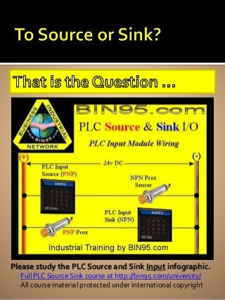
- 1. •Please study the PLC Source and Sink Input infographic. Please study the PLC Source and Sink Input infographic. Full PLC Source Sink course at http://bin95.com/university/ All course material protected under international copyright
- 2. Please study the PLC Source and Sink Output infographic. Full PLC Source Sink course at http://bin95.com/university/ All course material protected under international copyright
- 3. Please memorize these 3 points about Source and Sink. Full PLC Source Sink course at http://bin95.com/university/ All course material protected under international copyright
- 4. Pay attention to PNP/NPN if device has a Diode. Full PLC Source Sink course at http://bin95.com/university/ All course material protected under international copyright
- 5. Pay attention to PNP/NPN if device has a Transistor. Full PLC Source Sink course at http://bin95.com/university/ All course material protected under international copyright
- 6. Pay attention to PNP/NPN if device has a Transistor. Full PLC Source Sink course at http://bin95.com/university/ All course material protected under international copyright
- 7. Share this PLC Source and Sink PowerPoint with others. Full PLC Source Sink course at http://bin95.com/university/ All course material protected under international copyright
Notes de l'éditeur
- While delivering PLC training, customers often ask to clarify how PLC DC Source and Sink I/O works. This PLC http://www.slideshare.net/bin95/PLC-Source-Sink PowerPoint is part of the complete free PLC Source and Sink Course. The PLC Source and Sink Course consist of 4 interactive training modules, a video, online quiz and this PowerPoint. Definition: “Sink” and “Source”, are terms used to reference a DC device’s position in a circuit (commonly an electronic device specifically designed to be Sink or source), relative to another device’s position in that same circuit (same current flow path, from positive to negative). The device on the most positive side of circuit is referred to as the “Source”, and also as a PNP device. Like a DC source Output card. The device on the most negative side of circuit is referred to as the “Sink”, and also as NPN device. Like a DC Sink Input card. The options with PLC DC I/O (Input/Output), are … DC Source Input, DC Source Output, DC Sink Input or DC Sink Output.
- Just like the previous PLC input module slide, DC Source output cards (PNP output) will be on the most positive side of circuit in relation to the Sinking device that it is outputting to. (A relay in the above source– sink example.) Although relay above is not Source/PNP or Sink NPN dependant, depending on its position you refer to it as wired as a sink, or wired as a Source. Switch between these to first slides and study the relative positioning and terminology. Study the (+) (-) The source always has a positive (+) common, the sink always has a negative common. While PNP/NPN dependant devices are common to be used for PLC DC inputs, devices wired to PLC output are less common to be PNP/NPN dependant. An example of an output device that may be PNP/NPN dependant is an imaging camera or a solenoid valve. Most relays, limit switches, push buttons etc. are not polarity dependant and can be wired as sink or source. When you are talking Source and Sink, all things are relative. You may even have an input card you can change from sink to source or vise versa. An automation control designer chooses to use DC Source or Sink PLC I/O based on many factors. Common deciding factors are … Keeping it standard with what PLC I/O was used in the rest of control. Which is most commonly used in facility. What part of the world equipment will be used in. PLC DC Source output because the output shorting to positive is less likely than shorting to ground/negative. PLC DC Sink input because the input shorting to positive is less likely than shorting to ground/negative. What ever device to be wired to PLC I/O specifies because it was purchased before the PLC I/O.
- Even simpler … Source = PNP + Com Sink = NPN – Com You may be wondering what is PNP/NPN? For now, just know Positive Negative Positive (PNP) and Negative Positive Negative (NPN) A closer look PNP, it has 2 “P”s and only 1 “N”. So PNP is more positive than NPN which only has only 1 “P” (“Com” stands for the common terminal on PLC I/O module or I/O device.) Now that we have some of the simple basics and terminology out of the way, lets look at PLC Source and sink in a little more detail in the next slides.
- If you are a mechanic, you know a check valve blocks fluid flow in one direction. A diode is the check valve of electronics, blocking current flow in one direction. So if a DC device to be wired to a DC PLC input card or output card (I/O) has a diode, you need to pay attention to which way the diode is pointing and/or where it is placed in circuit. You need to know if that device is PNP or NPN, and have the opposite type I/O card to interact with it. Integrated Circuits (IC) chips, have transistors in them, transistors have diodes in them. So devices with any of the 3 electronic parts, are Source/Sink dependant. Note: DC Relays and DC Solenoids have a Diode on them too, as a circuit protection device. When a DC relay is powered off, the collapsing magnetic field of coil can generate up to 4 times the normal voltage, so the diode safely drains that shutdown voltage to ground in order to protect the generated current from going back into the circuit the relay or solenoid is wired to. With Direct Current (DC) and for the purpose of this simplified course, we’ll say Direct Current flows from Positive to Negative. The arrow in the schematic diagram for a diode points from positive to negative, indicating the allowed current flow direction.
- The Transistor is an electronic (solid state) switch and has a Diode in it. So if a DC device to be wired to a DC PLC input card or output card (I/O) has a transistor, you need to pay attention to where the diode(Emitter) is placed/pointing within the transistor (PNP or NPN transistor?) and where that device with transistor is placed within the PLC I/O circuit. If you use a PNP device for input, then you need a NPN (DC Sink) PLC input card. In the example pictured, a PNP transistor switches on the positive (+) to the PLC DC Sink (NPN) input card, when ever negative (-) is applied to the base (B) of the transistor. Notice the arrow/diode/emitter in transistor is pointing in the direction of the current flow allowed. From positive (+) to the more negative side of transitory (‘C’ Collector). Remember with DC voltage/current, everything is relative. (although both E and C of the transistor have positive voltages, C has more negative potential than E, so current flows from E to C for purpose of this illustration. With a PNP transistor, the emitter/arrow is on the more positive side, with a NPN transistor, the emitter/arrow is on the more negative side (the ‘C’ collector side). E = Emitter (arrow) B = Base (turns switch on and off) C = Collector
- Pictured above is an example of a NPN transistor being used for input. If you use a NPN device for input, then you need a PNP (DC Source) PLC input card. In the example pictured, a NPN transistor switches on the positive (-) to the PLC DC Source (PNP) input card, when ever negative (+) is applied to the base (B) of the transistor. Notice the arrow/diode/emitter in transistor is pointing in the direction of the current flow allowed. From positive (+) to the more negative side of transitory (‘E’ Emitter). As E is connected directly to the negative rail on the right. Remember with DC voltage/current, everything is relative. (although both C and E of the transistor are negative, E has more negative potential than C, so current flows from C to E for purpose of this illustration. A common way to identify if a transistor is PNP or NPN based on the schematic diagram alone, is to remember these phrases in relationship to what the emitter arrow is pointing to … PNP = Points iN Permanently NPN = Never Points iN (“Points iN” refers to point into the middle of transistor, points to in to the base.)
- Just some reminders here of previously mentioned points and a little extra Source and sink help. Not every device used with DC source or DC sink input and output cards is or has to be PNP or NPN. Electro-mechanical devices like a limit switch are not polarity dependant. The same limit switch can be use on the source side of the circuit or on the sink side. Our own little memory phrase is … The Positive Source is Sinking into the ground. Be sure to like and share this PowerPoint (in its entirety) with others. That encourages us to make more free online training courses. To see the Full Free Online PLC Source and Sinking Course … go to http://bin95.com/university/ Our free online courses provide 4 online interactive training modules, and online quiz and this PowerPoint.