1. US 20140138867A1
(19) United States
(12) Patent Application Publication (10) Pub. No.: US 2014/0138867 A1
Sullivan et al. (43) Pub. Date: May 22, 2014
(54) SELF-ADHERED SINGLE-SIDED (52) U.S. Cl.
SLIP-RESISTANT MATERIAL CPC ....... .. B29C 47/0026 (2013.01); B29C 4 7/0057
_ _ _ _ (2013.01); B29C 47/0042 (2013.01); B29C
(71) Applicant: Multl Technologies Industrial L.L.C., 47/0066 (201301); 329C 47/065 (201301);
Bremwood’ NH (Us) 329C 47/8805 (2013.01); 329C 47/8845
(72) Inventors: Michael C. Sullivan, Cape Elizabeth, USPCME (Us); Thomas Zickell, H, Winder ....................................................... .. .
Park, FL (US)
(21) Appl. No.: 14/054,095 (57) ABSTRACT
(22) Filed: Oct. 15, 2013
. . A single-sided, slip resistant, self-adhesive material is pro
Related U's' Apphcatlon Data duced using a blown ?lm process Which produces a ?lm
(63) Continuation of application No. 13/209,631, ?led on having an interior layer capable ofbeing treated or coated to
Aug. 15, 2011, now Pat. No. 8,632,706. accept a pressure sensitive adhesive, a middle layer of?exible
(60) Provisional application No. 61/373,957, ?led onAug. p.01yo.le?n .and an eXténorp01y01e?n elaswmq layer. In 0011.1
bmation W1th a blowmg agent to produce a s1ngle-s1ded slip
16, 2010. . . . . .
resistant material. A number of m-hne rollers are optionally
Publication Classi?cation provided after a pair of nip rollers, Which form part of a
machine direction orienter (MDO) that is used in line in the
(51) Int. Cl. manufacturing process to heat, and then cool and condition
B29C 47/00 (2006.01) (anneal and relieve any stresses and/or thickness inconsisten
B29C 47/88 (2006.01) cies) the ?lm prior to the ?lm being coated on one side With a
B29C 47/06 (2006.01) pressure sensitive adhesive.
3. US 2014/0138867 A1
SELF-ADHERED SINGLE-SIDED
SLIP-RESISTANT MATERIAL
CROSS-REFERENCE TO RELATED
APPLICATIONS
[0001] This application is a Continuation of US. patent
application Ser. No. 13/209,631 ?led on Aug. 15, 2011 titled
“Self-Adhered Single-Sided Slip-Resistant Material” which
in turn claims priority from US. Provisional Patent Applica
tion No. 61/373,957 titled “Self-Adhered Single-Sided Slip
Resistant Material” ?led onAug. 16, 2010 and both ofwhich
are incorporated fully herein by reference.
TECHNICAL FIELD
[0002] The present invention relates to slip resistant mate
rial and more particularly, relates to a transparent, self-ad
hered protective covering having a non-slip or slip-resistant
upper surface.
BACKGROUND INFORMATION
[0003] There is often a need for a transparent, all purpose,
lightweight, protective, self-adhered material to covermarine
craft surfaces, such as boat decks andhulls during moving and
storage, construction or other activities such as repair, reno
vation, painting and decorating or when exhibiting the boat to
the public. Many other uses for such a ?lm also exist. One
problem that has consistently been struggled with for such
material is the need of the material to be transparent, self
adhesive, and have a top surface that is slip resistant.
[0004] During boat maintenance, for example, there have
been some prior art attempts at using kraft paper and masking
tape to mask off surfaces prior to renovation. Paper does not
have UV resistance, is not terribly resistant to tearing, nor is
it impervious to moisture, all ofwhich are signi?cant factors
encountered in the marine industry.
[0005] Accordingly, what is needed is a lightweight, self
adhered, UV resistant, transparent ?lm like material that is
generally impervious to water and other liquids and resists
tearing while providing a non-slip or slip-resistant surface.
SUMMARY OF THE INVENTION
[0006] The present invention features a method of making
a single-sided, anti-slip ?lm comprising the acts of using a
?lm blowing machine to co-extrude a multi-layer ?lm
through a circular die to form a tube, wherein the tube
includes at least three co-extruded layers of?lm including an
inner layer, an outer layer and a middle layer. The outer layer
comprises a blowing agent that expands to form a slip resis
tant outer layer. The tube has a ?rst side and a second side,
each side including said at least three co-extruded layers.
[0007] The method next includes drawing the co-extruded
multi-layer ?lm tube vertically upwardly away from the cir
cular die at a predetermined speed. At a predetermined dis
tance from the circular die, the method next involves collaps
ing the co-extruded multi-layer ?lm tube by passing the ?lm
tube through at least two parallel rollers placed in close prox
imity to one another such that the ?rst roller contacts the ?rst
side ofthe coextruded multilayer ?lm tube, while the second
roller contacts the second side of the coextruded multilayer
?lm tube. The resultant collapsed, co-extruded, multi-layer
?lm has ?rst and second edges.
[0008] In one embodiment utiliZing an in-line Machine
Direction Orienter (MDO) the method of the invention
May 22, 2014
involves subsequently passing the collapsed, co-extruded,
multi-layer ?lm through a ?rst pair ofin-line rollers, wherein
at least one ofthe ?rst pair ofrollers is heated to a temperature
above a glass transition temperature and below a softening
point of the inner layer of said ?lm. The ?rst pair of in-line
rollers rotate at a speed that is approximately the same speed
as the predetermined speed at which the co-extruded multi
layer ?lm tube is drawn from the circular die.
[0009] The method including the embodiment utiliZing the
MDO next involves passing the ?lm through a second pair of
in-line rollers. At least one ofthe second pair ofin-line rollers
includes at least one roller which is operated at a temperature
which is cooler than the softening point of the inner layer of
the ?lm. The second pair ofin-line rollers rotate at a speedthat
is faster than the speed of the ?rst pair of in-line rollers,
thereby causing the ?lm to be stretched in at least one direc
tion.
[0010] In all embodiments, the method next involves cut
ting the collapsed, co-extruded, multi-layer ?lm proximate
the ?rst and second edges to form two generally identical ?lm
layers each with an inner surface and an outer surface, each
?lm layer having an outer surface that is non-slip.
[0011] In one embodiment, the method further includes
afterthe act ofcutting the collapsed, co-extruded, multi-layer
?lm proximate the ?rst and second edges to form two gener
ally identical ?lm layers, the act of applying a pressure sen
sitive adhesive to the inner surface of each of the two gener
ally identical ?lm layers. The adhesive may be acrylic based.
[0012] In a further embodiment, the outer layer may
include a plurality ofgas bubbles formed by the addition ofa
blowing agent added to the outer layer ofthe multi-layer ?lm
providedto the circular die. The ?lm blowing agent causes the
gas bubbles to be created in the outer layer as the outer layer
is co-extruded in the circular die. In a further embodiment, the
outer layer may include an UV stabilizer, an UV absorber and
an antioxidant. The outer layer may also include a polyole?n
elastomer based material and/or a grit material which adheres
to the outside ofthe gas bubbles formed by the blowing agent,
for providing additional slip resistance to the ?lm.
[0013] The middle layer may include a polyole?n material
as well as one or more of the following: an UV stabilizer, an
UV absorber and an antioxidant.
[0014] In a further embodiment, the method may include,
prior to the step ofapplying the pressure sensitive adhesive to
the inner layer, treating or coating the inner layer to enhance
the adhesion of the pressure sensitive adhesive to the inner
layer. For example, the inner layer may be treated with a
corona discharge treatment.
[0015] In yet another embodiment, at least one of the two
rollers is a rubber roller.
BRIEF DESCRIPTION OF THE DRAWINGS
[0016] These and other features and advantages of the
present invention will be better understood by reading the
following detailed description, taken together with the draw
ings wherein:
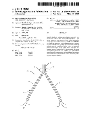
[0017] FIG. 1 is a perspective schematic view of a portion
ofa system for making the slip resistant material according to
the present invention; and
[0018] FIG. 2 is a schematic diagram of the travel path of
the single-sided, transparent, slip resistant material of the
present invention after the material has been blown showing
incorporation of a machine direction orienter (MDO) in-line
in the manufacturing process.
4. US 2014/0138867 A1
DETAILED DESCRIPTION OF THE PREFERRED
EMBODIMENTS
[0019] The present invention features a one-sided slip resis
tant material made by the well known blown ?lm process,
which process is well known in the industry, comprising the
co-extrusion of multiple layers to produce a ?nished ?lm
composite having the desired characteristics described
herein.
[0020] As illustrated in FIG. 1, a ?lm blowing machine (not
shown but well known in the art) produces a circular or
cylindrical ?lm “bubble” 10 comprising, in the preferred
embodiment and without limiting the present invention, 3
layers or ?lms: A, B and C. In the preferred embodiment,
layer A, (the inside most layer of the bubble) is an adhesive
coatable thermoplastic layer ofapproximately 0.2 to 2 mils in
thickness having a softening point in the range of2000 to 3000
E. which facilitates or accepts a coating ofa pressure sensitive
adhesive (PSA), as will be described below. LayerA may be
an LDPE, LLDPE, HDPE, PP, EVA, EMA POP (polyole?n
plastomer) or POE (polyole?n elastomer) resin based layer or
a blend of several such resins or other suitable resin(s). In
addition to the resin, this layer may also include a UV stabi
lizer, UV absorber, antioxidant, and processing or thermal
stabilizer.
[0021] Layer B, the central or center layer, is preferably a
?exible polyole?n layer having a thickness ofapproximately
0.5-2 mils. Suitable materials for the center B layer include,
but are not limited to, LDPE, LLDPE, TPO, POP (Polyole?n
Plastomer) and POE (Polyole?n Elastomer). In addition to
the resin this layer may also include a UV stabilizer, UV
absorber and antioxidant which will be exposed during the
manufacturing process after the formation of the collapsed
bubbles in the C layer.
[0022] The C layer (the outermost layer ofthe ?lm which
will form the top ofthe ?nished ?lm product) is also a ?exible
polyole?n layer. This layer, however, contains a “blowing”
agent that causes the ?lm to form many small “bubbles” on
the exterior surface 12 of the C layer. The blowing agent
creates a gas in the extruder during the melting process and
this gas is distributed throughout the C layer and is soluble in
the molten plastic due to the high extruder pressure. When the
?lm exits the blown ?lm die, there is a drop in pressure, and
bubbles form in the C layer. By stretching and cooling the
?lm, the bubbles collapse forming a rough, nonslip, open
celled “textured” surface 12.
[0023] The blowing agent can be either a physical blowing
agent (PBA) such as carbon dioxide or butane, or an exother
mic or endothermic chemical blowing agent (CBA) such as a
sodium bicarbonate and citric acid mixture which decom
poses under heat during the extrusion process and produces a
gas.
[0024] In the preferred embodiment, the preferred ?exible
polyole?n ofthe C layer is a polyole?n elastomer (POE) such
as Dow Chemical’s VersifyTM product and preferably, Ver
sifyTM 2300. After considerable experimentation, it has been
determined that not all polyole?n elastomers are suitable for
the skid resistance (non-slip) application. A resin with appro
priate melting point and softness to create bubbles that are
very rubbery, ?exible and high Coe?icient ofFriction (COF)
creating a surface with signi?cant “slip” resistance is
required. These characteristics, which can be found in the
VersifyTM 2300 product include: ?exural modulus less than
200 MPa, and Durometer hardness (Shore A) less than 100.
May 22, 2014
[0025] In addition to the polyole?n elastomer, layer C may
also include, a UV stabilizer, UV absorber and/or antioxidant,
as well as potentially a grit material such as ultra-high
molecular weight polyole?n which will adhere to the outside
of the bubbles formed by the blowing agent and add addi
tional slip resistance to the surface of the ?nished ?lm. The
blown ?lm before the blowing agent is activated is preferably
2.5 to 4 mils thick. After activating the blowing agent, the ?lm
“puffs” out and will have a thickness of approximately
between 6 and 12 mils.
[0026] Near the top ofthe bubble 14, two rollers 16, 18 (top
nip rollers) are utilized to “collapse” the top ofthe bubble 14
causing both insideA layers ofthe bubble 10 to come together
and abut one another but not to fuse or stick together. In the
preferred embodiment, one of the rollers is a rubber roller
while the other may be a rubber roller or a metal nip roller
although the nip rollers 16, 18 may be individually or both
made from either rubber, metal, plastic or any other suitable
material.
[0027] The processing ofthe ?lm layer 20 according to one
embodiment is shown schematically in FIG. 2. In this
embodiment, after the ?lm 20 leaves the rollers 16/18, the
?lm enters a set of in-line rollers 24-30 which serve as a
Machine Direction Orienter (MDO) generally shown as 22.
The rollers 24-30 ofthe MDO 22 serve as a post treatment of
the ?lm, annealing or conditioning the ?lm to take any
stresses out of the ?lm and to remove any variation in thick
ness. The MDO section preferably includes 2 pairs of2 rollers
each. The ?rst two rollers 24/26 are heated to a temperature
above the glass transition temperature and below the soften
ing point of the resin of the inside A layer of the ?lm 20 (in
order to prevent the two A layers from sticking to each other).
These rollers operate at a speedwhich is the same as the speed
at which the blown ?lm 20 is manufactured.
[0028] The next two rollers 28/30 are cooling rollers oper
ated at a temperature inthe range of80- 100° F. In addition, the
cooling rollers 28/30 are operated at a speed of 2% to 10%
faster than the line or manufacturing speed at which the ?rst
two rollers 24/26 operate. The pair of cooling rollers 28/30
serve to cool the ?lm down before it is wound into a roll for
later use. Although the use of an MDO is known in the art, it
is not known to place such a device “in line” in the manufac
turing process. Typically, in the prior art, a ?lm is blown,
wound onto a roll, subsequently unwound into an MDO for
stretching, and then rewound before use.
[0029] The set of in-line rollers 24-30, which serve as a
Machine Direction Orienter (MDO) 22 are optional and pro
vided in one embodiment while in another embodiment, the
MDO 22 may be omitted completely and replaced by only
such rollers as necessary to take up and process the ?lm 20 as
it comes off the ?lm blowing machine.
[0030] The ?lm 20, which has now gone through the MDO
(if provided), is next fed to an edge slitter 40, which is well
known in the art. The edge slitter 40 slits or cuts the two edges
of the ?lm separating it into two independent and identical
?lms 41 and 43 each being transparent, with slip resistant
layer C on one side. The two ?lms 41 and 43 are then fed to a
roller or winder which winds the ?lms into rolls of desired
size/length 42, 44. These rolls are then provided to a coating
system for applying a pressure sensitive adhesive, as
described below. Alternatively, the two ?lms 41, 43 may be
coated in-line after exiting the edge slitter40 andbefore being
wound.
5. US 2014/0138867 A1
[0031] The one-sided anti slip ?lm is coated with a self
adhering removable pressure sensitive adhesive (PSA). The
PSA can be a rubber based or more preferably, acrylic based
and is designed to adhere to the top surface of an object such
as a boat deck, typically a gel coat surface based on epoxy or
polyester resin. The PSA is formulated to provide good self
adhering properties, but is also removable and will not leave
a residue on the boat or other surface. Typically theA layer of
the antiskid ?lm is surface treated with a corona discharge
treater (CDT) or other treatment to increase the surface
energy of the ?lm and provide good adhesion of the PSA to
the ?lm. The PSA can be a water-based, solvent-based, or a
hotmelt andcanbe coatedusingtypical coatingmethods such
as knife over roll, reverse roll, gravure or other roll coating
methods.
[0032] Accordingly, the present invention provides a
single-sided, self-adhesive, transparent, non-slip, water
proof, UV resistant, non-yellowing ?lm which is easy and
relatively inexpensive to manufacture and which is slip resis
tant on one side, and can be used for numerous applications
such as painter’s drop cloths, non-slip protective coverings,
moving cloths and the like.
[0033] Modi?cations and substitutions by one of ordinary
skill in the art are considered to be within the scope of the
present invention, which is not to be limited except by the
allowed claims and their legal equivalents.
1-12. (canceled)
13. A method ofmaking single-sided, anti-slip ?lm layers,
each anti-slip ?lm payer having a rough, slip-resistant, open
celled outer surface on one ?lm side thereof, said method
comprising the following acts:
using a ?lm blowing machine to vertically coextrude a
multilayer ?lm from a circular die to form a tube having
?rst and second sides, wherein the tube comprises at
least three coextruded layers of ?lm including an inner
layer, an outer layer and a middle layer, said outer layer
comprising a plurality of gas bubbles resulting from
addition of a blowing agent to its ?lm making material
provided to said circular die, and said blowing agent
causing said gas bubbles to form in said outer layer as
said outer layer is coextruded from said circular die;
drawing the resulting coextruded multilayer ?lm tube ver
tically and upwardly away from the circular die at a
predetermined speed;
at a predetermined distance from the circular die, collaps
ing the coextruded multilayer ?lm tube during said
drawing by passing the ?lm tube between at least two
rollers positioned in close proximity to one another so
that a ?rst roller of said at least two rollers contacts said
?rst side of said coextruded multilayer ?lm tube and so
that a second roller of said at least two rollers contacts
said second side ofsaid coextruded multilayer ?lm tube,
wherein ?rst and second sides of the inner layer of said
?lm tube abut one another without fusing or sticking
together as a result of said collapsing, wherein surfaces
of said rollers contacting said ?rst and second sides of
said ?lm are parallel to one another, said collapsed,
co-extruded, multi-layer ?lm having ?rst and second
edges; and
cutting the multi-layer ?lm proximate said ?rst and second
edges to form two generally identical, single-sided ?lm
layers each with an inner surface and a non-slip outer
surface.
May 22, 2014
14. The method ofclaim 13 further comprising after the act
ofcutting the multi-layer ?lm proximate said ?rst and second
edges, the act ofapplying a pressure sensitive adhesive to said
inner surface of each of said two generally identical ?lm
layers.
15. The method of claim 13, further including after the act
ofpassing the ?lm tube between at least two rollers positioned
in close proximity to one another and before the act ofcutting
the multi-layer ?lmproximate said ?rst and second edges, the
acts of:
passing the collapsed, coextruded, multilayer ?lm through
a pair ofheated in-line rollers, wherein at least one roller
of said pair of heated in-line rollers is heated to a tem
perature above the glass transition temperature and
below the softening point ofthe inner layer of said ?lm
so as not to cause fusing ofsaid abutting ?rst and second
inner layer of sides, said pair of heated in-line rollers
rotating at approximately the same speed as said prede
termined speed at which said coextruded, multilayer
?lm tube is drawn from said circular die; and
subsequent to passing the collapsed, coextruded, multi
layer ?lm through said pair of heated in-line rollers,
passing the collapsed, coextruded, multilayer ?lm
through a pair of cooled in-line rollers rotating faster
than said pair of heated in-line rollers to thereby cause
the collapsed, coextruded, multilayer ?lm to stretch in at
least one direction, wherein at least one roller ofsaidpair
of cooled in-line rollers is operated at a temperature
coolerthan the softening point ofsaid inner layer ofsaid
?lm, wherein said plurality of gas bubbles in said outer
layer are collapsed by said stretching and cooling, and
wherein the resulting, cooled, multilayer ?lm is gener
ally free of stresses and of variation in thickness.
16. The method of claim 13, wherein said outer layer
comprises at least one ofthe following: a UV stabilizer, a UV
absorber and an antioxidant.
17. The method of claim 13, wherein the ?lm making
material of said outer layer is based on a polyole?n elastomer
based material.
18. The method of claim 13, wherein said outer layer
further comprises a grit material which adheres to the outside
of said gas bubbles formed by the blowing agent, thereby
providing additional slip resistance to the outer surface of
each generally identical ?lm layer.
19. The method of claim 13, wherein said middle layer
comprises a polyole?n material.
20. The method of claim 13, wherein said middle layer
comprises one or more ofthe following: a UV stabilizer, a UV
absorber and an antioxidant.
21. The method of claim 14, wherein prior to said act of
applying said pressure sensitive adhesive to said inner surface
of each of said two generally identical ?lm layers, said inner
surfaces are treated or coated to enhance adhesion of said
pressure sensitive adhesive to said inner surfaces.
22. The method of claim 21, wherein said treatment is
conducted by a corona discharge treater.
23. The method of claim 14, wherein the material of said
pressure sensitive adhesive is acrylic-based.
24. The method of claim 17 wherein said material of said
outer layer has a ?exural modulus ofless than 200 MPa and a
Shore A Durometer hardness of less than 100.
* * * * *