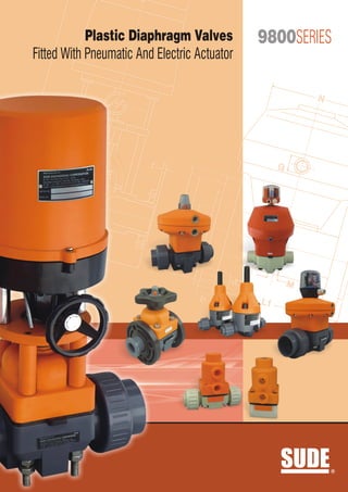
Plastic Diaphragm Valves Fitted With Pneumatic And Electric Actuator
•
0 j'aime•1,043 vues


Recommandé
Contenu connexe
Similaire à Plastic Diaphragm Valves Fitted With Pneumatic And Electric Actuator
Similaire à Plastic Diaphragm Valves Fitted With Pneumatic And Electric Actuator (20)
Plus de Chaitannya Mahatme
Plus de Chaitannya Mahatme (20)
Dernier
Dernier (20)
Plastic Diaphragm Valves Fitted With Pneumatic And Electric Actuator
- 1. A Plastic Diaphragm Valves 9800SERIES Fitted With Pneumatic And Electric Actuator N H b f G h D kd Z A L d2 M b L1 SUDE R
- 2. Plastic Diaphragm Valves Fitted With Pneumatic And Electric Actuator Index Introduction Introduction ........................................... 1 Sude offers – Imported Diaphragm valves are with one piece rugged body having cross ribs at flanged ends. They are available in size Specification .......................................... 2 range of 15mm to 100mm. Its latest inverted design diaphragm remains unstressed while valve is in close position so it gives more Optional Features & Accessories .......... 3 service life. The Diaphragm of these valves are available with Neoprene, EPDM, Hyplon, Butyl, PTFE-Coated and pure PTFE. The Advantages ........................................... 3 construction of valve with pure Teflon diaphragm, MS backing ring on bonnet and body which provide extra support and strength. Installation ............................................ 3 Diaphragms valves are with deep seat allow maximum flow and excellent flow characteristics. Repair And Maintenance ...................... 3 Plastic Diaphragm Valves are dependent on the design, especially suitable for highly – pure to heavily contaminated, liquid and gaseous Sectional View of Diaphragm Valve ..... 4 inert and corrosive media. Just as classical control valves also have good control properties, especially for media which is soiled or Types of Actuation ................................. 6 provided with particles. The major areas of use are the semiconductor industry and Types Of Operating Device microelectronic and a wide variety of industrial applications e.g. water And Its Construction .............................. 6 treatment. Electrical Actuator ................................. 7 The valve can be manually, pneumatically and as well as electrically operated. Pressure / Temperature Diagram ......... 9 GA Drawings Pneumatic Actuator with Diaphragm Valves ................................ 11 Electric Actuator with Diaphragm Valves ................................ 13 01 9800SERIES SUDE
- 3. Specification : SUDE Sude offers diaphragm valves which has no wetted metal Connection: components. The valve will never fail because of ? Spigot ends for solvent welding DIN / ISO (PVC-U, corrosion and they do not require painting or epoxy PVC-C) coating to stand up to aggressive environments. ? fusion welding DIN / ISO (PP, PVDF) Spigot ends for ? Single piece rugged body with cross ribs at flanged ? to DN 50 with socket end for fusion welding Union DN 15 ends. DIN /ISO (PP, PVDF) ? design diaphragm remains unstressed Latest inverted ? GFR or PP / steel flange PN 10/16 with DIN face-to-face while valve is in closed position, gives more service life. dimension ? maximum flow and excellent throttling Deep seat allows ? Union ends according to BS, ANSI, or JIS on request characteristics. ? can be provided as per BS. Table D, E or Flange drilling Nominal sizes: F, ANSI-ISO, DIN or any other standard. DN 10 – DN 100 ?is hydro tested at 10 kg / cm2 for body & Every valve seat. Body material: PVC-U, ABS, PP, PVDF, PFA, In liner PP-H, Outliner PP Control Pressure: reinforced Maximum 7 bar Seal material: Operating Temperature: Standard body diaphragm material is Neoprene whereas For valve materials: other materials such as Butyl, Hypalon, Teflon, EPDM, Viton, Nitrile and Teflon backed with Neoprene etc. can ? PVC up to+600C also be supplied on request ? PP up to+800C ? PVDF up to +1200C Body configuration: Straight through body ( 2/2-way valve), T-valve (3/2-way For Sealing Materials Temperature Limitation: valve), multi port valves in PVC-U, PP and PVDF on ? EPDM up to +900C request ? FPM up to +1200C ? EPDM / PTFE up to +900C Operator: Manual, Pneumatic, motorised Utilization: As shut-off valves as well as for controlling in process Mounting: plants. Variable Type of fluids: Option: Neutral, aggressive liquid or gaseous media even with Position Indicator, lift limit and manual emergency control abrasive particles provided that the components getting in from DN 65, Limit switch unit. contact with the medium are resistant at operating The Diaphragm Saver travel stop is a standard feature on temperature. all sizes of Diaphragm valves. Its special design prevents over compression of the diaphragm and prolongs its Nominal pressure: service life. ? PN 10 DN 15 – DN 50 Valves size up to 2” available with special type position indicator while larger sizes have a feature of a rising stem ? PN 6 DN 65 – DN100 indicator. SUDE 9800SERIES 02
- 4. Optional Features & Accessories SUDE Valves are supplied in 'Closed' condition with single acting, double acting Actuator. Optimal: Normally 'Open' construction, Double Acting Actuator, Electro Pneumatic valve Positioner, Valve travel Indicator with Limit switches and LED, Proximity Switch Sensors, Stroke Limiting Mechanism, Manual Override in lieu of some accessories, Namur 3-way and 4-way Solenoid Valves and the valves is also supplied with Electrical Actuator in case of motorised, generally supplied in on/off construction can be supplied with servo unit for modulating application. The valve design is abrasion – resistant and non – clogging. Slurries at low pressure that would normally clog most other valve designs easily pass through a diaphragm valve. The valve has a top entry design, allowing in – line maintenance; it is suitable for throttling and on / off service in applications ranging from water treatment to chemical abrasion processes. Diaphragm valves are operated Manually, Electrically, Pneumatically. Sude offers all plastic diaphragm valves have been specifically designed to perform in the most demanding liquid, gas and slurry applications in both ON / OFF and modulating service. Advantages SUDE ? Body and Diaphragm sizes have co-ordinate diameters hence the fitting time is reduced because the pipe and fixing centers remain the same. Spares inventory is also reduced. ? Optional accessories ? indication that the valve is in the open position Electrical remote ? wheel Lockable hand ? – saving design Compact, weight ? flow capability Good specific ? Body with integrated mounting facility Installation SUDE Sude offers flanged Diaphragm valves are designed for use with all ANSI Class 150-pipe flanges. When installing flanged Diaphragm valves dead end service, it is recommended to install between one pipe flange and a downstream blind flange. Soft rubber flange gaskets are required. Be sure to allow space between the mating flanges for the end-to end length of the valve plus the minimum thickness of the flange gasket. This will allow for proper installation, without distorting the gaskets when tightening the assembly. Use well lubricated studs or bolts and nuts. Use metal washers for plastic flanges between nut / bolt head and the flange. Use a torque wrench to uniformly tighten nut to approximately 10 foot pounds. Use an alternate sequence, diametrically opposed to the previously tightened nut. Use pipe hangers based on normal manufacturer recommendations. The valve shall not support the weight of the pipe. Repair And Maintenance: SUDE The most common repair required for Diaphragm Valve is the replacement of the Diaphragm itself. Fluid viscosity, chemical make-up and the frequency of cycle can affect the service life of the diaphragm. Replacement of the Diaphragm may be performed without removal of the valve from the system. The valve should be in the “Open” position. Remove the bonnet bolts and washers. Remove the bonnet with the Diaphragm. The Diaphragm should be separated from the compressor and bonnet. Rotate it counterclockwise from the compressor. When installing the new Diaphragm, be sure that the holes in the Diaphragm align with the holes in the bonnet. 03 9800SERIES SUDE
- 5. Sectional View of Diaphragm Valve (Single acting & Double acting Actuator) SUDE DN 15 bis DN 50 DN 15 bis DN 50 Fig. 1 Fig. 2 Item Qty. Description 1 1 Body 2 1 Diaphragm 3.1 1 Housing Actuator Body 3.2 1 Housing Actuator Bonnet 3.3 1 Pressure Piece 3.4 1 Driving Shaft 3.5 1 Disc 3.6 1 Diaphragm 3.7 1 Cap 3.8 1 Adjustment Screw 3.9 1 Pressure Spring 3.1 1 Pressure Spring 3.11 1 Banjo Bolt 3.12 10 Socket Head Cap Screw 3.13 10 U-washer 3.14 1 Circlip 3.15 1 O-ring 3.16 1 O-ring 3.17 1 O-ring 3.18 1 O-ring 3.19 1 Indicator Pin 3.2 2 Hexagonal Nut 3.21 2 Hexagonal Nut 3.22 1 Clamping Sleeve DN 15 bis DN 50 4 4 U-washer 5 4 Hexagonal Screw 7 2 Union Nut Fig. 3 8 2 Insert 9 2 O-ring SUDE 9800SERIES 04
- 6. SUDE Available Construction Double Acting / Single Acting : Model Number 9866/12/Double Acting or Single Acting 9866/15/Double Acting or Single Acting Note : Motorised not available 5 View A 57 G 1/4" 17 18 33 112 35 52 61 G 1/4" 33 15 14 57 G 3/8" G 1/4" 16 G 1/4" 90 19 G 3/8" 96 20 21 NC-NORMAL CLOSE NO-NORMAL OPEN Pos. Description 13 1 Body 13 2 Bonnet 9 6 6 3 Insert 11 4 Pressure Piece 8 11 5 Spindle 8 6 Indicator Pin 2 7 12 2 Diaphragm 12 8 Washer 9, 10 Pressure Spring 5 10 5 10 11 Nut 14 12 Piston 14 13, 14, 15 O-Ring Sealing 3 15 3 16 Identification Plate 15 4 17 Hexagon Socket Screw 4 7 18 Nut 7 19 Insert 1 1 20 O-Ring Sealing 21 Union Nut 05 9800SERIES SUDE
- 7. Types of Actuation SUDE Cylinder Actuator: ? free Actuator, spring sets made from plastic, encapsulated spring steel have optimum corrosion resistance Maintenance and reliable spring performance. ? process diaphragm prevents the elastomer from spreading out. Partly covered ? free piston actuator in high temperature plastic with a maximum temperature of 150º C. the relatively large Maintenance piston area allows for lower control pressures. ? with a visible indicator as standard. An extensive range of accessories is available which may be easily Valves are fitted fitted at any time. ? A polished stainless steel spindle traveling in a plain bearing guarantees a long life span for actuator. Types Of Operating Device And Its Construction SUDE ? Manually operated ?closed) NC(normally ? open) NO(normally ? DA(double acting) ?glass fiber reinforced. Standard PP ? with high temperature hand wheel and cover. Manual valves ? temperature + cover PP glass fiber reinforced. Lower part high ?high temperature valves autoclaving. Lower part + ? fiber reinforced. Blue PP glass ? fiber reinforced. Grey PP glass ? fiber reinforced. Red PP glass The intended use includes adhering to the specified limit values for pressure and temperature as well as the chemical resistance referring to the operating conditions. SUDE 9800SERIES 06
- 8. Electrical Actuator SUDE Sude offers single phase multi turn / linear actuator in two different models which is compact having stall duty motor. A compact stall duty synchronous motor, directly mounted on the base plate of spur gear box, drives gear train. The gear wheel of the last stage drives a special nut with trapezoidal thread, which in turn moves the non-twistable actuator stem upwards and down wards. The Important industries such as chemical, fine chemical, pharmaceutical & others dealing with industrial process prefer small & medium size valves. The special nut is, contrary to common practice followed in electric actuators, not rigidly fixed to the actuator frame, but is mounted and held in a middle position by an arrangement of spring washers. When the valve plug, connected via the valve stem to the actuator stem by a special coupling device, reaches the seat the “floating” nut compresses continuously the spring package and thereby steadily increases the closing force. Due to this, valve always maintains zero leakage. The two rigid steel rods connect the actuator with the control valve bonnet and serve in addition as travel indicator and anti-twist devices for the actuator stem. Sude actuator is always equipped with a hand wheel, which allows manual operation of the valve in emergencies or in case of power failure. The high grade aluminum housing tightly sealed by an O-ring, provides an excellent protection against dirt, dust and/or water, and conforms to protection class IP65/IP67. The Electrical Actuator has a positioner and Transmitter possible feed back, space heater to avoid water condensation, positioner for modulating control duty applications. Top Cover Positioner Card Limit Switches Position Transmitter Motor Housing Spur Gear Hand Wheel Actuator Stem Anti-Rotation Arrangement Stem Coupling 07 9800SERIES SUDE
- 9. Manual 220V AC / 50 Hz Positioning Input Signal Self- Control Power 4 to 20 mA Diagnostics Amplifier Sitch (Triac) Internal Position Feedback Actuator Type 2000 Control Action Direct / Revers Schematic Wiring Diagram of Electric Positioner M POT 1 Extra Limit Switches NC NO NC NO NC NO NC NO C C LSO LSC Open Close P N Position 230/110 V Transmitter 1 Ph, 50 Hz 4-20 mA Wiring Diagram with Standard & Optional Accessories Standard : Optional : Travel limit switches (1 NO + 1 NC) 2nos Auxiliary limit switches (1NO + 1NC) 2nos Hand wheel Valve positioner – Field/panel mounted Local position Indicator Two wire current Transmitter Remote position indicator with power source Analog/Digital Space Heater Field/panel mounted controller (PID) Special accessories on request SUDE 9800SERIES 08
- 10. Pressure / Temperature Diagram SUDE The pressure / temperature limits are applicable for the standard nominal pressures and a computed operating life of 25 years. The values are a guide for harmless media, to which the material of the valve is resistant. The durability of wear and tear parts depends on the operating conditions of the application. For temperatures below 0°C (PP < +10°C) please specify the precise operating conditions. Refer figure pressure / temperature diagram. Pressure / Temperature Diagram: PVC-U PVC-U PP PVDF PN 10 pressure (bar) PN 6 4 2 0 0 20 40 60 0 20 40 60 80 0 20 40 60 80 40 -20 0 20 40 60 80 100 120 0 temperature ( C) Pressure Loss Curve (Standard Values for H2O, 200C) ky (I/min)= 90 245 620 1.300 2.940 150 390 830 2.000 Flow characteristic 1,000 100 80 0 DN 2 DN 0 25 15 DN 40 DN 50 DN 65 DN 0 10 3 2 8 DN DN DN 0,100 kv-value (%) pressure loss p (bar) 0,050 60 40 0,010 0,005 20 0,001 0 3 5 10 20 50 100 500 1.000 5.000 0 20 40 60 80 100 Flow Q (I/min) Valve opening (%) Control Curve DN 15 - DN 50 Control Curve DN 65 - DN 100 6 6 con trol func con tion trol NC func Control Pressure (bar) Control Pressure (bar) tion 4 NC 4 O / DA on N l fu ncti n NO ntro contro l functio co 2 2 DA function control 0 0 0 2 4 6 8 10 0 2 4 6 8 10 Operating Pressure (bar) Operating Pressure (bar) 09 9800SERIES SUDE
- 11. Pneumatic Actuator with Diaphragm Valves SUDE 9860 N C G H d M h A W B d N C G G H d2 M d h Z W b K L D N C G H D1 d h M A L2 B L3 L4 W GFR PP/Steel PVC-U/ VALVE SIZE Actuator Model No B NC NO/DA Flange Flange D PVC-C PP PVDF d2 f G d(mm) DN (mm) DN (inch) PN (bar) C C b b D1 D1 D1 20 15 1/2" 10 9860/15/ON/OFF 72 29 41 12 13 95 41 46 47 14 6 1/4" 25 20 3/4" 10 9860/20/ON/OFF 72 29 41 14 14.5 105 50 56 57 14 7 1/4" 32 25 1" 10 9860/25/ON/OFF 92 29 41 15 15.5 115 58 66 64 14 7 1/4" 40 32 11/4" 10 9860/32/ON/OFF 92 29 41 17 17.5 140 72 79 78 18 8 1/4" 50 40 11/2" 10 9860/40/ON/OFF 119 41 41 17 17.5 150 79 87 89 18 8 1/4" 63 50 2" 10 9860/50/ON/OFF 119 41 41 18 19 165 98 107 109 18 9 1/4" PVC-U/ PVC-U/ PP/ WEIGHT (kg) NC NO/DA PVC-C PP PVDF M N PVC-C PVDF W Z h K L L1 L2 L3 PVC Spigot PP Spigot PVDF Spigot H1 H1 L4 L4 L4 t t PVC PVC PVC 136 113 26 65 130 124 90 96 128 125 128 M6 122 16 16 26 4 1.45 1.42 1.48 136 113 26 75 150 144 108 114 152 146 150 M6 122 19 19 26 4 1.48 1.43 1.51 175 139 26 85 160 154 116 122 166 158 162 M6 152 22 21 26 4 2.86 2.78 2.92 175 139 40 100 180 174 134 140 192 181 184 M8 152 26 23 45 4 2.92 2.82 3.02 207 155 40 110 200 194 154 160 222 207 210 M8 192 31 26 45 4 6.15 5.96 6.3 207 155 40 125 230 224 184 190 266 244 248 M8 192 38 30 45 4 6.25 6.03 6.45 SUDE 9800SERIES 10
- 12. Pneumatic Actuator with Diaphragm Valves SUDE 9860 N N G G H1 H1 d D kd h h t M M d2 L1 L1 b W W N N G G H1 H1 D k d d h h t M d2 M L L1 b W W GFR PP/Steel PVC-U/ VALVE SIZE Actuator Model No B NC NO/DA Flange Flange D PVC-C PP PVDF d2 f G d(mm) DN (mm) DN (inch) PN (bar) C C b b D1 D1 D1 75 65 2 1/2" 6 9860/65/ON/OFF - - - 18 19 185 - - - 18 - 1/4" 90 80 3" 6 9860/80/ON/OFF - - - 20 21 200 - - - 18 - 1/4" 110 100 4" 6 9860/100/ON/OFF - - - 20 22 220 - - - 18 - 1/4" PVC-U/ PVC-U/ PP/ WEIGHT (kg) NC NO/DA PVC-C PP PVDF M N PVC-C PVDF W Z h K L L1 L2 L3 PVC Spigot PP Spigot PVDF Spigot H1 H1 L4 L4 L4 t t PVC PVC PVC 325 305 55 145 220 284 - - - - - M12 258 44 33.5 100 4 15 14.50 15.50 325 305 55 160 310 300 - - - - - M12 250 58 38 100 8 15.50 15 16 355 330 64 180 350 340 - - - - - M12 258 61 41.5 120 8 25.50 25 26 11 9800SERIES SUDE
- 13. Electric Actuator with Diaphragm Valves SUDE 9850 H1 12 Thk. H d h t A B L1 W W M M A 12 Thk. H D1 G d h A B W L2 L3 L4 M SUDE 9800SERIES 12
- 14. Electric Actuator with Diaphragm Valves SUDE 9850 A H 12 Thk. f b d1 h Z A L K D W W M M VALVE SIZE GFR PP/Steel PVC-U/ PP PVDF Flange Flange PVC-C d DN DN PN Actuator Model No A B D d2 f H h k L L1 L2 L3 b b D1 D1 D1 (mm) (mm) (inch) (bar) 20 15 1/2" 10 9850/20/SD-2000-200-S/ON/OFF 90 72 12 13 95 41 46 47 14 6 270 26 65 130 124 90 96 25 20 3/4" 10 9850/25/SD-2000-200-S/ON/OFF 90 72 14 14.5 105 50 56 57 14 7 270 26 75 150 144 108 114 32 25 1" 10 9850/32/SD-2000-200-S/ON/OFF 100 92 15 15.5 115 58 66 64 14 7 270 26 85 160 154 116 122 40 32 1 1/4" 10 9850/40/SD-2000-200-S/ON/OFF 100 92 17 17.5 140 72 79 78 18 8 270 40 100 180 174 134 140 50 40 1 1/2" 10 9850/50/SD-2000-200-S/ON/OFF 130 119 17 17.5 150 79 87 89 18 8 270 40 110 200 194 154 160 63 50 2" 10 9850/63/SD-2000-600-S/ON/OFF 130 119 18 19 165 98 107 109 18 9 310 40 125 230 224 184 190 75 65 2 1/2" 10 9850/75/SD-2000-600-S/ON/OFF 190 177 18 19 185 — — — 18 10 310 54 145 290 284 — — 90 80 3" 10 9850/90/SD-2000-600-S/ON/OFF 190 177 20 21 200 — — — 18 11 310 54 160 310 300 — — 110 100 4" 10 9850/110/SD-2000-600-S/ON/OFF 190 217 20 22 220 — — — 18 12 310 64 180 350 340 — — PVC-U/ PVC-U/ PP/ WEIGHT (kg) PP PVDF PVC-C PVC-C PVDF PVC PVC PVC PP PP PP PVDF PVDF PVDF M V W Z Spigot Socket Flange Spigot Socket Flange Spigot Socket Flange L4 L4 L4 t t PVC PVC PVC PP PP PP PVDF PVDF PVDF 128 125 128 M6 16 16 — 26 4 5.38 5.5 5.82 5.32 5.4 5.76 5.44 5.55 5.88 152 146 150 M6 19 19 — 26 4 5.4 5.5 6.06 5.34 5.5 6 5.47 5.6 6.13 166 158 162 M6 22 21 — 26 4 5.83 6.1 6.63 5.7 5.9 6.5 5.97 6.25 6.77 192 181 184 M8 26 23 — 45 4 5.9 6.2 7.2 5.77 6 7.1 6.1 6.35 7.4 222 207 210 M8 31 26 — 45 4 6.8 7.1 8.2 6.5 6.8 7.9 7.2 7.4 8.6 266 244 248 M8 38 30 — 45 4 12.9 17.2 14.5 12.6 13.1 14.2 13.3 13.8 14.9 — — — M12 44 33.5 — 100 4 17.1 — 19.6 16.2 — 18.7 17.9 — 20.4 — — — M12 52 38 — 100 8 17.5 — 20.4 16.6 — 19.6 18.2 — 21.2 — — — M1C 61 45 60 120 8 20.5 — 23.7 19.2 — 22.4 21.7 — 24.9 13 9800SERIES SUDE
- 15. SUDE 9800SERIES 14
- 16. OUR OTHER PRODUCTS: Solenoid valves. Pneumatically operated control valves. motorised valves. Pneumatic & Electric Operated Ball / Butterfly valves. Pneumatic & motorised Dampers. Pneumatic & motorised VIV Dampers. Heavy duty – Single phase & Three phase actuators for operating Gates & chutes. motorised Rising & Non-rising Sluice valve. Pneumatic & motorised pinch valve. Pneumatic & motorised Flush Bottom valve. Pneumatic & Motorised Dampers. Entire range of Electrical Actuator. And Instrumentation Product likes Pressure Transmitter, PID Controller, Flow meter etc., for System Integration. NOTE : TECHNICAL SPECIFICATIONS, DETAILS & DIMENSIONS ARE SUBJECT TO CHANGE WITH PRIOR NOTICE. DIMENSIONS IN THE TABLE ARE APPROXIMATE SUBJECT TO FINAL CONFIRMATION BY SUDE. vignetgraphics. CAT/9800/09-10 Head Office, Bangalore SUDE ENGINEERING CORPORATION No. 1106, 10th Main Road, RPC Layout, Vijayanagar, Pune Office : SUDE Bangalore - 560 040. Karnataka, India S.No. 40/4, Balaji Udyam Nagar, Tempo Chowk, Tel. : 91 80 2330 2145 / 2314 1104 / 2340 2297 Wadgaon Sheri, Pune 411014. Maharashtra India. R Fax : 91 80 2330 5729 Tel. : 91 20 6533 3549 / 6531 1091 Cell : 091 9845018216 Fax : 91 20 2703 1161 E-mail : sudeengg@gmail.com Cell : 091 9822980003 sudeengg@dataone.in E-mail : scpl@sdtork.com