
Recommandé
Contenu connexe
Tendances
Tendances (20)
En vedette
En vedette (17)
Similaire à 1.seal mechanical seal
Similaire à 1.seal mechanical seal (20)
Plus de Chetan vadodariya
Plus de Chetan vadodariya (16)
Dernier
Dernier (20)
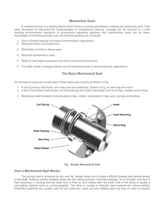
1.seal mechanical seal
- 1. Mechanical Seals A mechanical seal is a sealing device which forms a running seal between rotating and stationary parts. They were developed to overcome the disadvantages of compression packing. Leakage can be reduced to a level meeting environmental standards of government regulating agencies and maintenance costs can be lower. Advantages of mechanical seals over conventional packing are as follows: 1. Zero or limited leakage of product (meet emission regulations.) 2. Reduced friction and power loss. 3. Elimination of shaft or sleeve wear. 4. Reduced maintenance costs. 5. Ability to seal higher pressures and more corrosive environments. 6. The wide variety of designs allows use of mechanical seals in almost all pump applications. The Basic Mechanical Seal: All mechanical seals are constructed of three basic sets of parts as shown in Fig. 1. A set of primary seal faces: one rotary and one stationary. Shown in Fig. as seal ring and insert. 2. A set of secondary seals known as shaft pickings and insert mountings such as 0-rings, wedges and V-rings. 3. Mechanical seal hardware including gland rings, collars, compression rings, pins, springs and bellows. Fig. Simple Mechanical Seal How a Mechanical Seal Works: The primary seal is achieved by two very flat, lapped faces which create a difficult leakage path perpendicular to the shaft. Rubbing contact between these two flat mating surfaces minimizes leakage. As in all seals, one face is held stationary in housing and the other face is fixed to, and rotates with, the shaft. One of the faces is usually a non-galling material such as carbon-graphite. The other is usually a relatively hard material like silicon-carbide. Dissimilar materials are usually used for the stationary insert and the rotating seal ring face in order to prevent
- 2. adhesion of the two faces. The softer face usually has the smaller mating surface and is commonly called the wear nose. There are four main sealing points within an end face mechanical seal (Fig. 10). The primary seal is at the seal face, Point A. The leakage path at Point B is blocked by either an 0-ring, a V-ring or a wedge. Leakage paths at Points C and D are blocked by gaskets or 0-rings. Sealing Points for Mechanical Seal The faces in a typical mechanical seal are lubricated with a boundary layer of gas or liquid between the faces. In designing seals for the desired leakage, seal life, and energy consumption, the designer must consider how the faces are to be lubricated and select from a number of modes of seal face lubrication. To select the best seal design, it's necessary to know as much as possible about the operating conditions and the product to be sealed. Complete information about the product and environment will allow selection of the best seal for the application. Mechanical Seal Types Mechanical seals can be classified into several types and arrangements: PUSHER: Incorporate secondary seals that move axially along a shaft or sleeve to maintain contact at the seal faces. This feature compensates for seal face wear and wobble due to misalignment. The pusher seals' advantage is that it's
- 3. inexpensive and commercially available in a wide range of sizes and configurations. Its disadvantage is that ft's prone to secondary seal hang-up and fretting of the shaft or sleeve. Examples are Dura RO and Crane Type 9T. UNBALANCED: They are inexpensive, leak less, and are more stable when subjected to vibration, misalignment, and Cavitation. The disadvantage is their relative low pressure limit. If the closing force exerted on the seal faces exceeds the pressure limit, the lubricating film between the faces is squeezed out and the highly loaded dry running seal fails. Examples are the Dura RO and Crane 9T. CONVENTIONAL: Examples are the Dura RO and Crane Type 1 which require setting and alignment of the seal (single, double, tandem) on the shaft or sleeve of the pump. Although setting a mechanical seal is relatively simple, today's emphasis on reducing maintenance costs has increased preference for cartridge seals.
- 4. NON-PUSHER: The non-pusher or bellows seal does not have to move along the shaft or sleeve to maintain seal face contact, The main advantages are its ability to handle high and low temperature applications, and does not require a secondary seal (not prone to secondary seal hang-up). A disadvantage of this style seal is that its thin bellows cross sections must be upgraded for use in corrosive environments Examples are Dura CBR and Crane 215, and Sealol 680. BALANCED: Balancing a mechanical seal involves a simple design change, which reduces the hydraulic forces acting to close the seal faces. Balanced seals have higher-pressure limits, lower seal face loading, and generate less heat. This makes them well suited to handle liquids with poor lubricity and high vapor pressures such as light hydrocarbons. Examples are Dura CBR and PBR and Crane 98T and 215.
- 5. CARTRIDGE: Examples are Dura P-SO and Crane 1100 which have the mechanical seal pre mounted on a sleeve including the gland and fit directly over the Model 3196 shaft or shaft sleeve (available single, double, tandem). The major benefit, of course is no requirement for the usual seal setting measurements for their installation. Cartridge seals lower maintenance costs and reduce seal setting errors Mechanical Seal Arrangements SINGLE INSIDE: This is the most common type of mechanical seal. These seals are easily modified to accommodate seal flush plans and can be balanced to withstand high seal environment pressures. Recommended for relatively clear non- corrosive and corrosive liquids with satisfactory' lubricating properties where cost of operation does not exceed that of a double seal. Examples are Dura RO and CBR and Crane 9T and 215. Reference Conventional Seal. SINGLE OUTSIDE: If an extremely corrosive liquid has good lubricating properties, an outside seal offers an economical alternative to the expensive metal required for an inside seal to resist corrosion. The disadvantage is that it is exposed outside of the pump which makes it vulnerable to damage from impact and hydraulic pressure works to open the seal faces so they have low pressure limits (balanced or unbalanced).
- 6. DOUBLE (DUAL PRESSURIZED): This arrangement is recommended for liquids that are not compatible with a single mechanical seal (i.e. liquids that are toxic, hazardous [regulated by the EPA], have suspended abrasives, or corrosives which require costly materials). The advantages of the double seal are that it can have five times the life of a single seal in severe environments. Also, the metal inner seal parts are never exposed to the liquid product being pumped, so viscous, abrasive, or thermosetting liquids are easily sealed without a need for expensive metallurgy. In addition, recent testing has shown that double seal life is virtually unaffected by process upset conditions during pump operation. A significant advantage of using a double seal over a single seal. The final decision between choosing a double or single seal comes down to the initial cost to purchase the seal, cost of operation of the seal, and environmental and user plant emission standards for leakage from seals. Examples are Dura double RO and X-200 and Crane double 811T.
- 7. DOUBLE GAS BARRIER (PRESSURIZED DUAL GAS): Very similar to cartridge double seals ... sealing involves an inert gas, like nitrogen, to act as a surface lubricant and coolant in place of a liquid barrier system or external flush required with conventional or cartridge double seals. This concept was developed because many barrier fluids commonly used with double seals can no longer be used due to new emission regulations. The gas barrier seal uses nitrogen or air as a harmless and inexpensive barrier fluid that helps prevent product emissions to the atmosphere and fully complies with emission regulations. The double gas barrier seal should be considered for use on toxic or hazardous liquids that are regulated or in situations where increased reliability is the required on an application. Examples are Dura GB2OO, GF2OO, and Crane 2800. TANDEM (DUAL UNPRESSURIZED): Due to health, safety, and environmental considerations, tandem seals have been used for products such as vinyl chloride, carbon monoxide, light hydrocarbons, and a wide range of other volatile, toxic, carcinogenic, or hazardous liquids Mechanical Seal Selection The proper selection of a mechanical seal can be made only if the full operating conditions are known: 1. Liquid 2. Pressure 3. Temperature 4. Characteristics of Liquid 5. Reliability and Emission Concerns 1. Liquid: Identification of the exact liquid to be handled is the first step in seal selection. The metal parts must be corrosion resistant, usually steel, bronze, stainless steel, or Hastelloy. The mating faces must also resist corrosion and wear. Carbon, ceramic, silicon carbide or tungsten carbide may be considered. Stationary sealing members of Buna, EPR, Viton and Teflon are common.
- 8. 2. Pressure: The proper type of seal, balanced or unbalanced, is based on the pressure on the seal and on the seal size. 3. Temperature: In part, determines the use of the sealing members. Materials must be selected to handle liquid temperature. 4. Characteristics of Liquid: Abrasive liquids create excessive wear and short seal life. Double seals or clear liquid flushing from an external source allow the use of mechanical seals on these difficult liquids. On light hydrocarbons balanced seals are often used for longer seal life even though pressures are low. 5. Reliability and Emission Concerns: The seal type and arrangement selected must meet the desired reliability and emission standards for the pump application. Double seals and double gas barrier seals are becoming the seals of choice. Seal Environment The number one cause of pump downtime is failure of the shaft seal. These failures are normally the result of an unfavorable seal environment such as improper heat dissipation (cooling), poor lubrication of seal faces, or seals operating in liquids containing solids, air or vapors. To achieve maximum reliability of a seal application, proper choices of seal housings (standard bore stuffing box, large bore, or large tapered bore seal chamber) and seal environmental controls (CPI and API seal flush plans) must be made. STANDARD BORE STUFFING BOX COVER Designed thirty years ago specifically for packing. Also accommodates mechanical seals (clamped seat outside seals and conventional double seals.)
- 9. CONVENTIONAL LARGE BORE SEAL CHAMBER Designed specifically for mechanical seals. Large bore provides increased life of seals through improved lubrication and cooling of faces. Seal environment should be controlled through use of CPI or API flush plans. Often available with internal bypass to provide circulation of liquid to faces without using external flush. Ideal for conventional or cartridge single mechanical seals in conjunction with a flush and throat bushing in bottom of chamber. Also excellent for conventional or cartridge double or tandem seals. LARGE BORE SEAL CHAMBERS Introduced in the mid-8o's, enlarged bore seal chambers with increased radial clearance between the mechanical seal and seal chamber wall, provide better circulation of liquid to and from seal faces. Improved lubrication and heat removal (cooling) of seal faces extend seal life and lower maintenance costs.
- 10. BigBoreTM Seal Chamber Taper Bore TM Seal Large Tapered Bore Seal Chambers Provide increased circulation of liquid at seal faces without use of external flush. Offers advantages of lower maintenance costs, elimination of tubing/piping, lower utility costs (associated with seal flushing) and extended seal reliability. The tapered bore seal chamber is commonly available with ANSI chemical pumps. API process pumps use conventional large bore seal chambers. Paper stock pumps use both conventional large bore and large tapered bore seal chambers. Only tapered bore seal chambers with flow modifiers provide expected reliability on services with or without solids, air or vapors. Conventional Tapered Bore Seal Chamber: Mechanical Seals Fall When Solids or Vapors Am Present in Liquid Many users have applied the conventional tapered bore seal chamber to improve seal life on services containing solids or vapors. Seals in this environment failed prematurely due to entrapped solids and vapors. Severe erosion of seal and pump parts, damaged seal faces and dry running were the result.
- 11. Modified Tapered Bore Seal Chamber with Axial Ribs: Good for Services Containing Air, Minimum Solids This type of seal chamber will provide better seal life when air or vapors are present in the liquid. The axial ribs prevent entrapment of vapors through. Improved flow in the chamber. Dry running failures are eliminated. In addition, solids less than 1% are not a problem. The new flow pattern, however, still places the seal in the path of solids/liquid flow. The consequence on services with significant solids (greater than 1%) is solids packing the seal spring or bellows, solids impingement on seal faces and ultimate seal failure. Goulds Standard Taper BoreTM PLUS Seal Chamber: The Best Solution for Services Containing Solids and Air or Vapors To eliminate seal failures on services containing vapors as well as solids, the flow pattern must direct solids away from the mechanical seal, and purge air and vapors. Goulds Standard TaperBoreTM PLUS completely reconfigures the flow in the seal chamber with the result that seal failures due to solids are eliminated. Air and vapors are efficiently removed eliminating dry run failures. Extended seal and pump life with lower maintenance costs are the results.
- 12. Magnetic Drive Pumps INTRODUCTION Environmental concerns and recurring mechanical seal problems have created a need for seal less pumps in the chemical and petrochemical industries. In some cases, more stringent regulations by the EPA, OSHA and local agencies are mandating the use of seal less pumps. One type of seal less pump is the magnetic drive pump which uses a permanent magnetic coupling to transmit torque to the impeller without the need for a mechanical seal for packing. PRINCIPLES OF OPERATION Magnetic drive pumps use a standard electric motor to drive a set of permanent magnets that are mounted on a carrier or drive assembly located outside of the containment shell. The drive magnet assembly is mounted on a second shaft which is driven by a standard motor. The external rotating magnetic field drives the inner rotor. The coaxial synchronous torque coupling consists of two rings of permanent magnets as shown in Fig. 1. A magnetic force field is established between the north and south pole magnets in the drive and driven assemblies. This provides the no slip or synchronous capability of the torque coupling. The magnetic field is shown as dashed lines and shaded areas in Fig. 3.
- 13. Two Types of Magnetic Drive Pump A. Rotating Driven Shaft
- 14. This type of design typically uses metal components and is best suited for heavy duty applications. The metallic construction offers the best strength, temperature and pressure capability required for heavy duty applications. Corrosion resistant high alloy materials such as 316SS, Hastelloy, and Alloy 20 are offered. The rotating shaft does, however, increase the number of parts required and thus increases the complexity and cost of the pump. This type of design typically uses a pressurized recirculation circuit, which helps prevent vaporization of liquid required for process lubricated bearings. (Refer to Model 3296, Section CHEM-3A). In the following section we'll be looking at overviews of several pump and seal subjects: • Centrifugal pump selection. • Centrifugal pump installation. • Centrifugal pump modifications you can make to increase the pump's performance. • Mechanical seal selection. In these tutorials I am attempting to put each of the subjects into perspective. You'll use the tutorials for multiple purposes: • To learn the terms we use for each of these individual subjects. • To see how the various subjects fit together. • To find out how much you know about any one of the subjects. • And you can use the tutorials as an outline to teach the subjects to other people. CENTRIFUGAL PUMP SELECTION. HOW TO PICK THE CORRECT SIZE PUMP FOR YOUR APPLICATION. We'll begin by deciding what operating conditions our pump has to meet and then we'll approach pump suppliers to see how closely they can satisfy these needs. Unfortunately no comprehensive theory which would permit the complete hydrodynamic design of a centrifugal pump has evolved in the many years that pumps have been around, so the pump manufacturer will be doing the best he can with the information you supply to him. To clearly define the capacity and pressure needs of our system we'll construct a type of graph called a system curve. This system curve will then be given to the pump suppliers and they will try to match it with a pump curve that satisfies these needs as closely as possible. To start the construction of the system curve I'll assume you want to pump some fluid from point "A" to point "B". To do that efficiently you must make a couple of decisions:
- 15. • Decide the capacity you'll need. This means the gallons per minute or cubic meters per hour. You must also consider if this capacity will change with the operation of your process. A boiler feed pump is an example of an application that needs a constant pressure with varying capacities to meet a changing steam demand. The demand for boiler water is regulated by opening and closing a control valve on the discharge side of the pump with a discharge re-circulation line returning the unneeded portion back to a convenient storage place, or the suction side of the pump. Remember that with a centrifugal pump if you change its capacity you change the pressure also. A rotary or positive displacement pump is different. It puts out a constant capacity regardless of the pressure. • For other centrifugal pump applications, you're going to have to calculate how much pressure will be needed to deliver different capacities to the place where you'll need them. You'll need enough pressure to : o Reach the maximum static head or height the fluid will have to attain. o Enough discharge pressure to over come any pressure that might be in the vessel where the fluid is discharging, such as the boiler we just discussed. This is called the pressure head. o Overcome friction resistance in the lines, fittings and any valves or hardware that might be in the system. As an example: high-pressure nozzles can be tricky, especially if they clog up. This resistance is called the friction head. • Will you need any special materials for the pump components? o The pump manufacturer will try to choose pump metal components that are chemically compatible with what you're pumping as well as any cleaners or solvents that might be flushed through the lines. If the temperature of the pump age changes, the corrosion rate can change also. His choice of materials could have a serious affect on your spare parts inventory. Will he be selecting universal and easily obtainable materials? Unless you have a great deal of experience with the product you're pumping, do not select the metal components by using a compatibility chart. Metal selection is a job for metallurgists, or your own experience. o If the product you're pumping is explosive, or a fire hazard, you should be looking at non- sparking materials for the pump components. Don't depend totally upon the pump manufacturer to make this decision for you. If you're not sure what materials are compatible with your product, how will the pump man know? Also, keep in mind that some of the fluids you'll be pumping could be proprietary products known only by their trade name. o Dangerous and radioactive materials will dictate special materials. o Food products require high-density seal and pump materials that are easy to clean. o If there are abrasive solids in the pumpage you'll need materials with good wearing capabilities. Hard surfaces and chemically resistant materials are often incompatible. You may have to go to some type of coating on the pump wetted parts or select an expensive duplex metal. • Occasionally you'll find an application where metal is either not compatible, or not practical. There are many monomer and polymer materials available for these applications, but their cost is generally higher than comparable metal parts. Be aware that if you're using a mechanical seal in a non-metallic
- 16. pump, the seal cannot have metal parts in contact with the fluid, for the same reasons the pump was manufactured from non-metallic materials. Use a non-metallic seal in these applications Since we're just getting into the subject, one of the first things we should learn is that centrifugal pump people do not use the word pressure. As mentioned in an earlier paragraph they substitute the word "head", so you'll have to calculate the three kinds of head that will be combined together to give you the total head of the system needed to deliver the required capacity. Here are the three kinds of head you'll be calculating: • The static head or maximum height that the liquid will reach. We must also learn how to compensate for the siphon affect from down running pipes on the discharge side of the pump. Remember that if you fill a tank from the bottom instead of the top, the static head will continually increase. This is not a good application for a centrifugal pump because the capacity is decreasing with an increasing head. If you must fill from the bottom, or if you'll be using the pump as an accumulator, a rotary positive displacement pump will be your best choice as long as it can meet the needed capacities. • The pressure heads are next, if the container we are pumping to, or from, is pressurized. We'll have to learn how to convert pressure units to head units because, later on, we will need this conversion knowledge to read the manufacturers pump curve. Pump gages are labeled in psi or bar. Pump curves are labeled in feet of head, or meters of head. • The friction head is the last one that we'll have to calculate. This head tells us how much friction or resistance head there is in both the suction and discharge piping, along with the fittings and valves in the piping system. And to make the job a little tougher this head changes dramatically as the pump capacity changes. You'll be calculating these heads on both the suction and discharge side of the pump. To get the total head you'll subtract the suction head from the discharge head and that will be the head that the pump must produce to satisfy the application. It'll become obvious in the calculations, but I should mention here, that if the suction head is a negative number, the suction and discharge heads will be added together to get the total head. If you subtract a minus number from a positive number you must add the numbers together. As an example: 4 - (-2) = + 6 The total head of a pump seldom remains static. There are a number of factors that can change the head of a pump while it's operating, and you should become familiar with most of them. All of this head information is calculated from piping, valve, and fitting, along with friction graphs you'll find in the index. This head data will be plotted on a set of coordinates called a system curve. Since we'll not be operating at a single point all of the time, we'll make the calculations for a range of different capacities and heads that we might expect to encounter. This range is described as the operating window we need to satisfy the application. Making these calculations is not an exact science because the piping is seldom new; pipe inside diameters are not exact, and the graphs you'll be consulting cannot compensate for corrosion and any solids built up on the piping, valve and fitting walls. Life is never simple. This is the point where most people start adding in safety factors to compensate for some of the unknowns. These safety factors will almost always guarantee the selection of an oversized pump that will run off of its best efficiency point (BEP) most of the time. The final calculations are then plotted on the system curve that describes what the pump has to do to satisfy the requirements of the application. You can learn to do all of this by referencing the following subjects:
- 17. • Calculating the total head in metric units • Calculating the total head in USCS (inch) units • Making a system curve, S111 The pump manufacturer requires a certain amount of net positive suction head required (NPSHR) to prevent the pump from cavitating. He shows that number on his pump curve. When you look at the curve you'll also note that the net positive suction head required (NPSHR) increases with any increase in the pump's capacity. You'll also be calculating the net positive suction head available (NPSHA) to be sure that the pump you select will not cavitate. Cavitation is caused by cavities or bubbles in the fluid collapsing on the impeller and volute. In the pump business we recognize several different types of Cavitation. : • Vaporization Cavitation. • Internal recirculation Cavitation. • Flow turbulence Cavitation. • Vane Passing Syndrome Cavitation. • Air ingestion (Not a real Cavitation, but it acts like it.) Pump Cavitation is recognized in several different ways • We can hear cavitation because it sounds like the pump is moving rocks or ball bearings. • We can see the damage from cavitation on the pump's impeller and volute. • The operator can sometimes tell if the pump is cavitating because of a reduction in the pump's capacity. • The main problem with cavitation is that it shakes and bends the shaft causing both seal and bearing problems. We call all of this shaking and bending shaft deflection. Remember that the net positive suction head required (NPSHR) number shown on the pump curve is for fresh water at 68° Fahrenheit (20°C) and not the fluid or combinations of fluids you'll be pumping. When you make your calculations for net positive suction head available (NPSHA) the formula you'll be using will adjust for the specific gravity of your fluid. • In some cases you can reduce the NPSH required. This is especially true if you are pumping hot water or mixed hydrocarbons. • You may have to install an inducer on the pump, add a booster pump, or go to a double suction pump design if you don't have enough net positive suction head available (NPSHA) When the pump supplier has all of this in-exact information in his possession he can then hopefully select the correct size pump and driver for the job. Since he wants to quote a competitive price, he is now going to make some critical decisions: He might begin with the type of pump he'll recommend: • If the capacity is going to be very low he would recommend a rotary, or positive displacement (PD) pump.
- 18. • Between 25 and 500 gpm (5 m3 /hr - 115 m3 /hr) he'll probably select a single stage end suction centrifugal pump. It all depends upon the supplier. At higher capacities he may go to a double suction design with a wide impeller, two pumps in parallel or maybe a high-speed pump. • You might need a high head, low capacity pump. The pump supplier has several options you should learn about. • Will he recommend a self-priming pump? These pumps remove air from the impeller eye and suction side of the pump. Some operating conditions dictate the need for a self-priming design. If you don't have a self-priming pump, and you are on intermittent service, will priming become a problem the next time you start the pump? • How will the pump be operated? o If the pump is going to run twenty-four hours a day, seven days a week and you're not going to open and close valves; you'll not need a heavy-duty pump. It's easy to select a pump that'll run at its best efficiency point and at the best efficiency point (BEP) there is very little shaft displacement and vibration. o Intermittent service is the more difficult application because of changing temperatures, vibration levels, thrust direction, etc. o Intermittent pumps require a more robust, heavy-duty design with a low L3 /D4 shaft. • How important is efficiency in your application? High efficiency is desirable, but you pay a price for efficiency in higher maintenance costs and a limited operating window. You should be looking for performance, reliability, and efficiency in that order. Too often the engineer specifies efficiency and loses the other two. The following designs solve some operation and maintenance problems, but their efficiency is lower than conventional centrifugal pumps. o A magnetic drive or canned pump may be your best choice if you can live with the several limitations they impose. o A vortex or slurry pump design may be needed if there are lot of solids or "stringy" material in the pumpage. o A double volute centrifugal pump can eliminate many of the seal problems we experience when we operate off the pump's best efficiency point. The problem is trying to find a supplier that will supply one for your application. Although readily available for impellers larger than 14 inches (355 mm) in diameter they have become very scarce in the smaller diameters because of their less efficient design. • The supplier should recommend a centerline design to avoid the problems caused by thermal expansion of the wet end if you are operating at temperatures over 200°F (100°C)? • Will you need a volute or circular casing? Volute casings build a higher head; circular casing are used for low head and high capacity. • Do you need a pump that meets a standard? ANSI, API, DIN, VDMA or ISO are some of the current standards. You should be aware of pump standards problems that contribute to premature seal and
- 19. bearing failures. An ANSI (American National Standards Institute) standard back pullout design pump has many advantages but presents problems with mechanical seals when the impeller clearance is adjusted, unless you're purchasing cartridge seals. • The decision to use either a single or multistage pump will be determined by the head the pump must produce to meet the capacities you need. Some suppliers like to recommend a high speed small pump to be competitive, other suppliers might recommend a more expensive low speed large pump to lessen NPSH and wear problems. There are additional decisions that have to be made about the type of pump the supplier will recommend: • Will the pump be supplied with a mechanical seal or packing? If the stuffing box is at negative pressure (vacuum) a seal will be necessary to prevent air ingestion. • If he's going to supply a mechanical seal, will he also supply an oversized stuffing box and any environmental controls that might be needed? • Will he specify a jacketed stuffing box so that the temperature of the sealed fluid can be regulated? How does he intend to control the stuffing box temperature? Will he be using water, steam or maybe a combination of both? Electric heating is sometimes an option. • How will the open or semi-open impeller be adjusted to the volute casing or back plate? Can the mechanical seal face loading be adjusted at the same time? If not, the seal face load will change and the seal life will be shortened. • If the pump is going to be supplied with a closed impeller you should have some means of knowing when the wear rings have to be replaced. If the wear ring clearance becomes too large the pumps efficiency will be lowered causing heat and vibration problems. Most manufacturers require that you disassemble the pump to check the wear ring clearance and replace the rings when this clearance doubles. • Will he supply a "C" or "D" frame adapter, or will the pump to motor alignment have to be done manually using dual indicators or a laser aligner to get the readings? A closed-coupled design can eliminate the need for an alignment between the pump and driver. • What type of coupling will he select to connect the pump to its driver? Couplings can compensate for axial growth of the shaft and transmit torque to the impeller. They cannot compensate for pump to driver misalignment as much as we would like them to. Universal joints are especially bad because they have to be misaligned to be lubricated. • He may decide to run two pumps in parallel operation if he needs a real high capacity, or two pumps in series operation if he needs a high head. Pumps that run in parallel or series require that they are running at the same speed. This can be a problem for some induction motors.. • An inline pump design can solve many pipe strain and thermal growth problems. • The pump supplier must insure that the pump will not be operating at a critical speed or passing through a critical speed at start up. If he has decided to use a variable speed drive or motor this becomes a possibility.
- 20. • We all want pumps with a low net positive suction head required to prevent cavitation problems but sometimes it's not practical. The manufacturer has the option of installing an inducer or altering the pump design to lower the net positive suction head required, but if he goes too far all of the internal clearances will have to be perfect to prevent cavitation problems. This modification of the impeller to get the low net positive suction head required (NPSHR) and its affects will be explained when you learn about suction specific speed. • The difference between specific speed and suction specific speed can be confusing but you should know the difference. • Shaft speed is an important decision. Speed affects pump component wear and NPSH requirements, along with the head, capacity, and the pump size. High speed pumps cost less initially, but the maintenance costs can be staggering. Speed is especially critical if you are going to be specifying a slurry pump. • The ratio of the shaft diameter to its length is called the shaft L3 /D4 number. This ratio will have a major affect on the operating window of the pump and its inital cost. The lower the number the better, but any thing below 60 (2 in the metric system) is acceptable when you are using mechanical seals. A low L3 /D4 can be costly in a standard long shaft pump design because it dictates a large diameter shaft that is usually found only on expensive heavy-duty pumps. A short shaft with a smaller outside diameter would accomplish the same goal, but then the pump would no longer conform to the ANSI or ISO standard. We often run into L3 /D4 problems when you specify, or the pump supplier sells you a low cost, corrosion resistant sleeve, mounted on a steel shaft rather than a more expensive solid, corrosion resistant shaft. There are multiple decisions to be made about the impeller selection and not all pump suppliers are qualified to make them: • The impeller shape or specific speed number will dictate the shape of the pump curve, the NPSH required and influence the efficiency of the pump. • Has the impeller configuration been iterated in recent years? Impeller design is improving with some of the newer computer programs that have become available to the design engineer. • The suction specific speed number of the impeller will often predict if you're going to experience a cavitation problem. • The impeller material must be chosen for both chemical compatibility and wear resistance. You should consider one of the duplex metals because most corrosion resistant materials are too soft for the demands of a pump impeller. • The decision to use a closed impeller, open impeller, semi-open, or vortex design is another decision to be made. • Closed impellers require wear rings and these wear rings present another maintenance problem. o Open and semi-open impellers are less likely to clog, but need manual adjustment to the volute or back-plate to get the proper impeller setting and prevent internal recirculation.
- 21. o Vortex pump impellers are great for solids and "stringy" materials but they are up to 50% less efficient than conventional designs. • Investment cast impellers are usually superior to sand cast versions because you can cast compound curves with the investment casting process. The compound curve allows the impeller to pump abrasive fluids with less vane wear. • If you're going to pump low specific gravity fluids with an open impeller, a non-sparking type metal may be needed to prevent a fire or explosion. You'll be better off choosing a closed impeller design with soft wear rings in these applications. • The affinity laws will predict the affect of changing the impeller speed or diameter. You'll want to be familiar with these laws for both centrifugal and PD pumps.. Either you or the supplier must select the correct size electric motor, or some other type of driver for the pump. The decision will be dictated by the specific gravity of the liquid you'll be pumping along with the specific gravity of any cleaners or solvents that might be flushed through the lines. The selection will also be influenced by how far you'll venture off the best efficiency point (BEP) on the capacity side of the pump curve. If this number is under-estimated there is a danger of burning out some electric motors. • How are you going to vary the pump's capacity? Are you going to open and close a valve or maybe you'll be using a variable speed drive like a gasoline or diesel engine. Will the regulating valve open and close automatically like a boiler feed valve or will it be operated manually? The variable speed motor might be an alternative if the major part of the system head is friction head rather than static or pressure head. • The viscosity of the fluid is another consideration because it will affect the head, capacity, efficiency and power requirement of the pump. You should know about viscosity and how the viscosity of the pumpage will affect the performance of the pump. There are some viscosity corrections you should make to the pump curve when you pump viscous fluids. • After carefully considering all of the above, the pump supplier will select a pump type and size, present his quote and give you a copy of his pump curve. Hopefully you'll be getting his best pump technology. To be sure that is true, you should know what the best pumping technology is. • At this stage it is important for you to be able to read the pump curve. To do that you must understand: o Efficiency o Best efficiency point (BEP) o Shut off head. o How to convert pressure to head so you can reference pump gage readings to the pump curve. When you learn the three formulas you'll get the conversion information. o Brake horsepower (BHP) o Water horsepower (WHP)
- 22. o Capacity o Net positive suction head required (NPSHR) o How to calculate the net positive suction head available (NPSHA) to the pump to insure you'll not have a cavitation problem. If all of the above decisions were made correctly, the pump supplier will place his pump curve on top of your system curve and the required operating window will fall within the pump's operating window on either side of the best efficiency point (BEP). Additionally, the motor will not overheat and the pump should not cavitate. If the decisions were made incorrectly the pump will operate where the pump and system curves intersect and that will not be close to, or at the best efficiency point, producing radial impeller loading problems that will cause shaft deflection, resulting in premature seal and bearing failures. Needless to say the motor or driver will be adversely affected also. With few exceptions pump manufacturers are generally not involved in mechanical sealing. You'll probably be contacting separate seal suppliers for their recommendation about the mechanical seal. Mergers between pump and seal companies unfortunately does not produce the instant expertise we would like sales and service people to posses. CENTRIFUGAL PUMP INSTALLATION Some one has to install the pump and all of its associated hardware. The quality of this pump and driver installation will have a major affect on the performance and reliability of the pump, especially if it's equipped with a mechanical seal. The pump will be installed on a baseplate. The baseplate will be attached to a foundation and grout will be placed between the baseplate and the foundation to transmit any vibrations from the pump to the foundation. Once the pump and driver are firmly on the foundation it'll be time to connect the piping. Be sure to pipe from the pump to the pipe rack and not the other way, so as to avoid pipe strain that will interfere with the operation of the mechanical seal and bearings. There are many piping recommendations that you should be familiar with. The leveling, and pump to driver alignment can be made at this point, but you should check the alignment after the pump has come up to its operating temperature because metal parts expand and contract with a change in temperature. If this is a new piping system some people like to install packing in the pump and run on packing until the new piping has been cleaned of slag or any junk that might be left in the piping system. If it's not a new installation, and there is a mechanical seal in the stuffing box, then installing the mechanical seal environmental controls will come next. If the pump has an open or semi-open impeller it's time to make the initial impeller clearance setting. The final clearance can be set when the pump comes up to its operating temperature. It's important to note that if you do not have a cartridge seal installed in the pump the seal face loading will change as you make both the initial and subsequent impeller settings and there is nothing you can do about it. You'll now want to do a proper venting of the pump. If it's a vertical installation you'll have to pay particular attention to keeping air vented from the stuffing box while the pump is running and be sure to vent the space between dual seals if they've been installed. After you have done all of the above, it's time to check out the mechanical seal environmental controls to be sure they're working properly. In most cases the environmental control will continue to run after the pump has stopped. Be sure the operators understand this or they might be tempted to
- 23. shut the control off when the pump is between batches. Seal quench is always a problem with operators because the steam or water dripping out of the seal gland looks like the seal is leaking. A constant monitoring of the pump is a good idea. Are you familiar with some of the more popular monitoring methods? Unlike vibration analysis, monitoring can tell you if some part of the pump is getting into trouble before the vibration starts. CENTRIFUGAL PUMP MODIFICATION If you find that your present centrifugal pump is not satisfying the application and running as trouble free as you would like, and you have checked: • All of the internal tolerances are correct. • There is no excessive pipe strain. • The open impeller has been adjusted to the volute or backplate after the pump came up to operating temperature. • The pump to driver alignment was made. • The rotating parts were dynamically balanced. • The wear-ring clearance is within manufacturers specifications. • The pump is running at the correct speed, in the right direction, with the correct size impeller. Then you may have to purchase a different centrifugal pump, or you might want to consider modifying the existing pump to get the performance and reliability you are looking for. Here are a few modifications and pump upgrades you can consider: • Modifying the impeller diameter could get you closer to the best efficiency point. The affinity laws will predict the affect of substituting a larger impeller, or the trimming the present impeller will have on the pump's head; capacity, net positive suction head required (NPSHR), and horsepower requirement. • Converting to an impeller with a different specific speed number will change the shape of the pump curve, power consumption and the NPSH required. • Changing to a heavy-duty power end can stop a lot of shaft deflection, and with some pump manufacturers get you the pilot diameter you need to install a "C or D" frame adapter to eliminate pump alignment. • Converting from a sleeved to a solid, corrosion resistant shaft will often reduce or stop shaft deflection problems caused by operating off the best efficiency point (BEP). If you're using mechanical seals be sure that you're using the type that prevents fretting corrosion. Most original equipment manufactured (OEM) seals damage shafts, and that's one of the main reasons they supply a sacrificial sleeve.
- 24. • Reducing the overhung shaft length can solve many shaft deflection problems. You should be able to get the L3 /D4 number down to a desirable 15-20 (0,5 &endash; 0,6 metric) by either reducing the shaft length or increasing the shaft diameter. • Changing the wet end to a double volute configuration will allow the pump to operate in a larger window without the danger of deflecting the shaft too much. • You can drill a hole in the end of the stuffing box, at the top, to increase stuffing box venting. • Change the flushing or recirculation connection from the top lantern ring connection to the bottom of the stuffing box to insure a better fluid flow through the stuffing box. Try to get close to the seal faces. • Enlarging the inside diameter of the stuffing box or going to an oversize stuffing box can solve some persistent seal problems. • Converting the wet end of the pump to a centerline design might solve some pipe strain problems by compensating for radial thermal growth. • Increasing the impeller to cutwater clearance could stop a cavitation problem • Installing a sight glass in the bearing case can help you maintain the correct oil level and prevent overheating problems in the bearings. • Replacing the bearing case grease or lip seals with either labyrinth or positive face seals for bearings will keep moisture out of the bearing case and eliminate a lot of premature bearing failure. • Converting the radial bearing retention snap ring to a more rugged holding device will eliminate many of he problems associated with axial movement of the shaft. • Converting the packed pump to a good mechanical seal will reduce power consumption and product leakage. • Converting solid mechanical seals to split mechanical seals can reduce the time it takes to change seals and eliminate the need for other trades to become involved in the process of disassembling a pump and bringing it into the shop. MECHANICAL SEAL SELECTION • In the following pages I'll be using the word "pump" to describe the piece of equipment that you'll be sealing. If your equipment is anything other than a single stage centrifugal pump with an over hung impeller, the information still applies with a couple of exceptions: o Mixers, agitators and similar pieces of equipment sometimes have severe axial thrust and shaft deflection problems due to their high L3 /D4 numbers (The ratio of the shaft length to its diameter). o Sleeve or journal bearing equipment allows more axial movement of the shaft than those pieces of equipment provided with precision bearings. Axial movement is a problem for mechanical seals because of the changing face load; especially at start up when the axial thrust reverses in a centrifugal pump.
- 25. o Open impeller pumps require impeller adjustment that could cause excessive axial movement of the shaft that will affect the seal face loading. Depending upon the severity of the abrasives being pumped, this could be a frequent occurrence. o Multi-stage pumps are seldom as sensitive to operating off the best efficiency point (BEP) as single stage centrifugal pumps. The opposing cutwaters in these pumps tend to cancel out the radial forces created when the pump is operating off of its best efficiency point (BEP). o Centrifugal pumps equipped with double volutes are not too sensitive to operating off the best efficiency point (BEP), but do experience all of the other types of shaft deflection. o Specialized equipment such as a refiner in a paper mill will experience a great deal of axial travel as the internal clearances are adjusted. Whenever I use the word fluid, I am talking about either a liquid or a gas. If I say either liquid or gas, I am limiting my discussion to that one phase of the fluid. Any discussion of mechanical face seals requires that you have many different types of knowledge. The first is, "should you be converting packed pumps to a mechanical seal?" Seals cost a lot more money than conventional packing and unless you're using split seals, they can be a lot more difficult to install. There is a packing conversion down side. Assuming you have made the decision that the mechanical seal is your best choice for sealing, you must know how to select the correct design for your application. There are many different kinds of seals to choose from: • Rotating seals where the springs or bellows rotate with the shaft. • Stationary seals where the springs or bellows do not rotate with the shaft. • Metal bellows seals used to eliminate elastomers that can have trouble with temperature extremes or fluid compatibility. • Elastomer type seals utilizing O-rings and other shape elastomers. • Single seals for most applications. • Dual seal designs for dangerous and expensive products or any time back up protection is needed. • Inside mounted designs that take advantage of centrifugal force to throw solids away from the lapped seal faces. • Outside seals. Usually the non-metallic variety for pumps manufactured from non-metallic materials. • Cartridge seals to ease installation and allow you to make impeller adjustments without disturbing the seal face loading. • Split seal designs that allow you to install and change seals without taking the pump apart and disturbing the alignment. • Hydrodynamic or non-contacting seals used for the sealing of gases. • Hydrostatic designs are another version of non-contacting vapor seals.
- 26. There are some very desirable design features that you should specify for your mechanical seals: • The ability to seal fugitive emissions without the use of dual seals, other than having the dual seal installed as a "back-up" or spare seal. • Will the seal dynamic elastomer damage or cause fretting corrosion of the pump shaft? Almost all- original equipment designs do. Spring-loaded Teflon® and graphite are notorious for shaft destruction. There are many seal designs available that will not cause fretting corrosion or damage shafts and sleeves, and that is the kind you should be using. • The seal should have built in non-clogging features such as springs out of the fluid. • The seal should be able to compensate for a reasonable amount of both radial and axial movement of the shaft. There are special mixer seal designs that can compensate for axial and radial travel in excess of 0.125 inches (3 mm) and you should know about them • The seal should be designed to be positioned as close to the bearings as possible to lessen the affects of shaft deflection. Ideally the seal would be located between the stuffing box face and the bearing case with a large diameter seal gland allowing plenty of internal radial clearance for the seal. • The seal should generate only a small amount of heat. Seal face heat generation can be a problem with many fluids and there's no advantage in letting the seal faces, or the fluid surrounding them get hot o Any heat generation between the seal faces should be efficiently removed by conduction away from the lapped faces and dynamic elastomer. Check to see if your design does it efficiently. • Any dynamic elastomer (an O-ring is typical) should have the ability to flex and then roll, or slide to a clean surface as the carbon face wears. • The seal face load should be adjustable to compensate for open impeller adjustments and axial growth of the shaft. Cartridge seals do this very well. • Can you use universal materials to lower your inventory costs and avoid mix-up problems? All of the seal materials should be clearly identified by type and grade. You'll need this information if you have to analyze a premature seal failure. Some seal companies try to make everything a secret. Do not tolerate it! • Will the seals be hydraulically balanced to prevent the generation of unwanted heat between the lapped faces? What is the percentage of balance? If you are using dual seals will the inner seal be a double balanced seal that is hydraulically balanced in both directions? Pressures can reverse in dual seal applications. • You'll want to become familiar with the effects of heat on: o The seal faces, especially the carbon and plated or coated hard faces o The elastomers, especially the dynamic elastomer o Excessive corrosion of the seal components.
- 27. o The product. It can change with heat. It can vaporize, solidify, crystallize, coke or build a film with an increase in the product's temperature. o Internal tolerances of the seal especially face flatness and elastomer squeeze. Heat causes thermal growth of these components that will alter their critical tolerances. We'd like to be able to install the seal without having to modify the pump. The seal should be the shortest, thinnest design that'll satisfy all of the operating conditions. Once you have the shortest, thinnest design that'll satisfy the operating conditions, there is seldom a need to modify any seal design. The specific sealing application will dictate which seal design you should choose. If your seal application falls within the following parameters any stationary or rotating, "off the shelf" balanced, o-ring seal should be able to handle the application without any serious problems: • Stuffing box pressures from a one Torr vacuum to 400 psi. (28 bar). Note that stuffing box pressure is normally closer to suction than discharge pressure • Stuffing box temperature from -40°F to 400°F. (-40°C to 200°C) • Shaft speed within electric motor speeds. If the surface speed at the seal faces exceeds 5000 fpm. (25 m/sec) you'll have to select the stationary version of the seal. • Shaft sizes from 1 inch to 4 inches. (25 mm to 100 mm) You may have to go to a special seal design if your application falls into any of the following categories: • Stuffing box pressures in excess of 400 psi. (28 bar) require heavy duty seals. • Excessive shaft movement of the type you find in mixers, agitators, and some types of sleeve or journal bearing equipment. • The seal must meet fugitive emission standards. • No metal parts are allowed in the system. You need a non-metallic seal. • Nothing black is allowed in the system because of a fear of color contamination. You cannot use any form of carbon face; you must use two hard faces. • There's not enough room to install a standard seal. • You're not allowed to use an environmental control or no environmental control is available. • Odd shaft sizes often dictate special seals. • If the seal components must be manufactured from an exotic metal. If any of the following are part of the application, you may need a metal bellows design that eliminates all elastomer.
- 28. • You're sealing a non-petroleum fluid and the stuffing box temperature exceeds 400°F (200°C) Petroleum fluids have coking problems that require cooling in the seal area. • Cryogenic temperatures. You should go to a dual seal application if your product falls into any of the following categories: • You need two seals to control the seal environment outside the stuffing box. • To control the temperature at a seal face to stop a product from vaporizing, solidifying, crystallizing, or building a film. • To prevent a pressure drop across a seal face that can cause a liquid to vaporize. • To eliminate atmospheric conditions outboard of a mechanical seal when there is a possibility of freezing water vapor in the air. • To break down the pressure in a high-pressure application, by inserting an intermediate pressure between the seals. Two lower pressure seals can then be used to seal a high-pressure fluid that would normally require a very expensive high-pressure mechanical seal. • To provide a lubricant if one is needed to prevent slip stick between lapped seal faces. This is always a problem when you are sealing a gas or non-lubricating liquid. You need dual seals as a protection for personnel in the area if your product is any of the following categories: • A toxic liquid or gas. • A fire hazard • A pollutant • A carcinogen • A radioactive fluid • An explosive fluid • Etc. The other places we use dual seals are: • Expensive products that are too valuable to let leak. • You cannot afford to be shut down in the middle of a batch operation. • You do not have a standby pump and experience shows that the seal failure is your highest probability of an unexpected shut down. In the Sealing Application section you'll learn:
- 29. • How to choose the correct seal materials. • How to classify the fluid into specific sealing categories • The environmental controls you might need to insure the seal will not fail prematurely. FREQUENT asked questions What is considered good life for a mechanical seal? • The only part of a mechanical seal that is supposed to be sacrificial is the carbon face. The seal should run leak free until the carbon face is worn away. If the seal leaks for any other reason we consider it a premature failure and always correctable. • Two hard faces are selected when carbon is not acceptable in the application and you have run out of options. You are then trying to get the longest life you can. • The only variable in seal life should be the lubricating quality of the product you're sealing. Hot water, many gases and most solvents are typical non-lubricants. • With all of that said, the fact is that in excess of eighty-five percent of mechanical seals fail prematurely. When seals are removed from the running pump most of the carbon face is still intact. Little face wear is the rule not the exception. Why do most seals fail prematurely? • One of the seal components becomes damaged. • The seal faces open. What are the most common causes of component damage? • Corrosion of one of the seal components. • Physical damage that includes the affects of high heat or excessive pressure What are the most common causes for the lapped seal faces to open? • The seal was set screwed to a hardened shaft. • Solids in the product you are sealing are clogging the moveable components. • The product changed state and interfered with the free movement of the seal. It: o Crystallized. o Became viscous. o Solidified. o Built a film on the sliding components and the lapped faces.
- 30. o The product vaporized across the lapped faces blowing them open. Do seal faces have to be lubricated? Can they run dry? • The graphite in the carbon/graphite face is a natural lubricant. In operation the graphite separates from the mixture and transfers to the hard face. This means that the seal face combination you are normally running is carbon on graphite. The hard face is just some place to put the graphite. • Moisture must be present for the graphite to separate from the carbon/graphite mixture. • Running dry means higher heat at the faces. If you are using a good unfilled carbon/graphite (and you should be) the faces are not going to be your problem. The elastomer and the product you are sealing can be very sensitive to a temperature change in the stuffing box, or an increase of temperature at the seal faces. Do seal faces have to be kept cool? • Most carbons and hard faces can tolerate a lot of heat. The elastomers (rubber parts) are the parts you have to watch. They are the most sensitive to a change in stuffing box temperature, especially if they are positioned in the seal face. • Hydraulically balanced seals generate very little heat between the faces. • Unbalanced seals usually require cooling because of the excessive heat they can generate. • Some face combinations generate more heat than others. Two hard faces as an example. • Some seal materials conduct heat better than others. Ceramic is a poor heat conductor and carbon is not much better. Tungsten carbide and silicone carbide are excellent conductors of heat. When should you use two hard faces? • With any of the oxidizing agents. • When sealing any of the halogens. • If the product tends to stick the faces together. • If you are sealing hot oil and you have to pass a fugitive emission test. • Some de-ionized water will attack carbon in any form. • When you are not allowed anything black in the system because of the possibility of color contamination. • Any time carbon/graphite will not work for some reason. • If the specifications call for two hard faces. Why not standardize on two hard faces? • They generate higher heat than the carbon/ hard face combination.
- 31. • They are not very forgiving. If the faces are not dead flat at installation, they seldom lap them selves flat in operation. Do seals have to leak? • Any good quality mechanical seal should run without visible leakage. • Single, stationary, (the springs do not rotate) hydraulically balanced mechanical seals can pass a fugitive emission test as long as the rotating portion of the seal is designed to be located square to the shaft. • Rotating seals (the springs rotate with the shaft) seldom can pass a fugitive emission test. They are too sensitive to various forms of misalignment. • Cartridge mounted stationary seals usually fail fugitive emission testing because the set screwing of the cartridge to the shaft prevents the rotating face from positioning its self square to the shaft. Some seal companies offer some type of a self aligning design to solve this problem. Why do most original equipment seal designs frett and damage the shaft under the dynamic elastomer or spring loaded Teflon. • Corrosion resistant shafts and sleeves protect themselves from corrosion by forming a protective oxide (ceramic) layer on the metal surface. The dynamic elastomer in the seal polishes this layer away as the shaft slides through the elastomer because of shaft vibration, pipe strain, misalignment etc. • The ceramic protective oxide that is removed by the polishing action imbeds its self into the elastomer causing it to act as a grinding wheel that increases the sleeve or shaft damage. Do you have to flush most slurry applications? • It depends upon the percentage of solids. Most fluid with entrained solids can run without flush if you have met the following conditions: o The packing stuffing box has been replaced with a larger inside diameter version. Centrifugal force will throw the solids away from the lapped seal faces. o You are using a hydraulically balanced seal that generates low heat. o The seal springs are not located in the fluid. o The fluid is at the seal outside diameter. o The dynamic elastomer moves to a clean surface as the carbon wears. o You are using suction recirculation to get flow in the stuffing box. I am looking for a simple solution to a difficult problem. Do discharge recirculation filters or cyclone separators installed between the pump discharge and the stuffing box make sense in slurry applications? • I wish they did! Filters clog and then there is no circulation in the stuffing box.
- 32. • Cyclone separators were never intended to be a single pass devise. The also require a substantial difference in pressure between the discharge and the clean liquid connections. In a pump application these pressures are too close together. If I put a higher fluid pressure barrier fluid between dual seals, shouldn't that keep the faces clean? • No, the clean fluid always takes the path of least resistance. That is the same reason that higher pressure air does not keep dry solids from penetrating the lapped faces. • Centrifugal force will pack solids in front of the inboard seal face and restrict its movement. Do you need a higher pressure barrier fluid between dual seals? • Higher pressure is called barrier fluid; lower pressure is called buffer fluid. • The only dual seals that require a barrier fluid are the "back to back" rotating, unbalanced versions, and you shouldn't use them any way. • Balanced tandem seals (one behind the other) use a buffer fluid that will not dilute your product if the inner seal fails. They also put the pumping fluid at the inner seal outside diameter where it belongs. • Dual seals should be hydraulically balanced in both directions so that they will stay shut regardless of the direction of the fluid pressure. How does seal hydraulic balance work? • There are two forces closing the seal faces. o A spring force caused by the spring, springs, or bellows pushing on the seal face. o A hydraulic force caused by the pressure of the fluid acting on the closing area of the seal faces. • There are three forces opening the mechanical seal: o A hydraulic force caused by fluid or vapor trapped between the lapped faces. o Centrifugal force that is causing the rotating portion of the seal to try and become perpendicular to the rotating shaft. o Hydrodynamic forces generated between the seal faces because for all practical purposes liquids are not compressible. • We balance these forces by reducing the closing area of the seal faces and thereby reduce the closing force. This is usually done by a small sleeve inserted into the seal or as step machined into the shaft. Metal bellows seals have an effective diameter measured through the bellows to accomplish the same thing. Is it O.K. to have a third party rebuild my mechanical seals?
- 33. • Not really. If you're happy with your seal have the manufacturer, or the company that sold it to you do the rebuilding. Here are a couple of reasons why: o Carbon/graphite has to be molded in a sintering process and the third party doesn't own the molds for your carbon/graphite face. Machined carbons don't have the density required for good seal faces. o There are many grades of elastomers. How do you insure you have the right grade. You can't tell by looking at the part. o Lapping is a real art. The temperature has to be closely controlled to get the right flatness. Should I be using split mechanical seals? • There are places where they are the only logical solution: o Double ended pumps. If one seal is leaking why take the pump apart and change both? Change only the one that is leaking. o Large vertical pumps. Sometimes you have to take the roof off the building to remove the solid mechanical seal. o Large size shafts are a natural for split seals. o Changing a seal means doing a re-alignment. Why go through that again? o If you have to remove a lot of pump insulation to get to the seal. o If the pump is in an awkward location, split seals make sense. • Many split seal designs can run with no visible leakage, but they seldom can pass a fugitive emission test that calls for leak rates in the order of parts per million. If I touch the lapped faces, are they ruined? • Not at all. Touching seal faces seldom causes problems. We are trying to keep solids from penetrating between the lapped faces, so the less you handle them the less likely solids will be deposited on the faces. Why should you not use stainless steel springs or stainless steel bellows in mechanical seals? • Chloride stress corrosion is the problem and chlorides are every where. Use hastelloy "C" springs and metal bellows and you'll never have this problem. Why not standardize on Teflon as the preferred rubber part in a mechanical seal? • Teflon® is not an elastomer, it doesn't have a memory and has to be spring-loaded to the sleeve or shaft. This spring loading interferes with the flexibility of the seal and prevents the elastomer part from flexing and rolling to compensate for minor shaft movements.
- 34. Why not mount the seal outside the stuffing box and then dirt and solids will not get into the springs and sliding parts of the mechanical seal? • The sealing fluid will be at the inside diameter of the lapped faces where centrifugal force will throw solids into the faces. • Solids will pile up in front of the seal preventing the faces from moving forward when the sacrifical carbon wears. What is a cartridge seal? • The rotating portion of the seal is mounted on a cartridge sleeve and this assembly is connected to the stationary portion of the seal along with the seal gland to form a cartridge assembly. Cartridge seals simplify the installation process and allow you to make impeller adjustments without upsetting the seal face loading. Do I need the new gas seals if I want to seal fugitive emissions? • Not really. Rotating seals do not pass fugitive emission tests because of their sensitivity to misalignment. Stationary seals usually do not have this limitation. • The difficulty arises when you try to install a stationary seal on a cartridge sleeve. When you tighten the sleeve set screws to the pump shaft you introduce misalignment between the rotating seal face and the rotating shaft. Hysteresis (delay or lag) problems take over and the result is the stationary seal design fails to pass the fugitive emission test. Any good cartridge mounted self aligning seal can resolve this problem. • Although a single seal can pass the test, a dual seal is recommended with a low pressure buffer fluid between the seals to act as a back up when the first seal wears out or fails. The buffer fluid will prevent unwanted product dilution and simplify the installation because there is no need for a compatible high pressure barrier fluid that is often hard to find. Why does my outside mounted seal make a whistling sound? • The seal faces are running dry. The product you are trying to seal is not a lubricant. Every time I remove a rubber bellows seal from my pump it is stuck to the shaft. Why? • It is supposed to vulcanize its self to the shaft so that it can drive the rotating face. If you can remove it easily something is wrong. You probably used the wrong lubricant on the rubber during installation. This is a case where the lubricant we use is supposed to attack the rubber and make it swell. When my metal bellows seal fails because of breakage at the plates, the break is always near the end fittings and never in the middle of the bellows. How is that explained? • This is the common mode of failure for excessive vibration. Metal bellows seals need some type of vibration damping to stop harmonic and "slip-stick" vibration problems.