9892124323 Pooja Nehwal Call Girls Services Call Girls service in Santacruz A...
vapor absorption_rc
1. Refrigeration Cycles Prof. U.S.P. Shet , Prof. T. Sundararajan and Prof. J.M . Mallikarjuna
Indian Institute of Technology Madras
6.7 Vapor Absorption Refrigeration System:
1
7 8
9 6
10
5
4
2 3
Evaporator
q0(T0)
Pump
qP
Heat exchager
Rectifier
qc(Tc=T
Strong
solution
NH3
generator
qn(Th)
T-valve
Condenser
T-valve
NH3
Absorber
Weak
solution
)
qa(Ta=T )
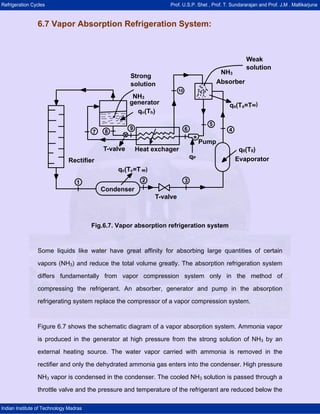
Fig.6.7. Vapor absorption refrigeration system
Some liquids like water have great affinity for absorbing large quantities of certain
vapors (NH3) and reduce the total volume greatly. The absorption refrigeration system
differs fundamentally from vapor compression system only in the method of
compressing the refrigerant. An absorber, generator and pump in the absorption
refrigerating system replace the compressor of a vapor compression system.
Figure 6.7 shows the schematic diagram of a vapor absorption system. Ammonia vapor
is produced in the generator at high pressure from the strong solution of NH3 by an
external heating source. The water vapor carried with ammonia is removed in the
rectifier and only the dehydrated ammonia gas enters into the condenser. High pressure
NH3 vapor is condensed in the condenser. The cooled NH3 solution is passed through a
throttle valve and the pressure and temperature of the refrigerant are reduced below the
2. Refrigeration Cycles Prof. U.S.P. Shet , Prof. T. Sundararajan and Prof. J.M . Mallikarjuna
Indian Institute of Technology Madras
temperature to be maintained in the evaporator. The low temperature refrigerant enters
the evaporator and absorbs the required heat from the evaporator and leaves the
evaporator as saturated vapor. Slightly superheated, low pressure NH3 vapor is
absorbed by the weak solution of NH3 which is sprayed in the absorber as shown in
Fig.6.7.
Weak NH3 solution (aqua–ammonia) entering the absorber becomes strong solution
after absorbing NH3 vapor and then it is pumped to the generator through the heat
exchanger. The pump increases the pressure of the strong solution to generator
pressure. The strong NH3 solution coming from the absorber absorbs heat form high
temperature weak NH3 solution in the heat exchanger. The solution in the generator
becomes weak as NH3 vapor comes out of it. The weak high temperature ammonia
solution from the generator is passed to the heat exchanger through the throttle valve.
The pressure of the liquid is reduced to the absorber pressure by the throttle valve.
Comparison between Vapor Compression and Absorption system:
Absorption system Compression System
a) Uses low grade energy like heat.
Therefore, may be worked on
exhaust systems from I.C engines,
etc.
a) Using high-grade energy like
mechanical work.
b) Moving parts are only in the pump,
which is a small element of the
system. Hence operation is smooth.
b) Moving parts are in the compressor.
Therefore, more wear, tear and noise.
c) The system can work on lower
evaporator pressures also without
affecting the COP.
c) The COP decreases considerably with
decrease in evaporator pressure.
d) No effect of reducing the load on
performance.
d) Performance is adversely affected at
partial loads.
e) Liquid traces of refrigerant present in
piping at the exit of evaporator
e) Liquid traces in suction line may
damage the compressor.
3. Refrigeration Cycles Prof. U.S.P. Shet , Prof. T. Sundararajan and Prof. J.M . Mallikarjuna
Indian Institute of Technology Madras
constitute no danger.
f) Automatic operation for controlling
the capacity is easy.
f) It is difficult.