![[object Object],[object Object],[object Object],[object Object],[object Object],[object Object],[object Object],[object Object],[object Object],[object Object],[object Object],Emergency Power System Selective Coordination](data:image/gif;base64,R0lGODlhAQABAIAAAAAAAP///yH5BAEAAAAALAAAAAABAAEAAAIBRAA7)
Recommended
Recommended
More Related Content
What's hot
What's hot (20)
Similar to Nfpa Wsc&E 080602
Similar to Nfpa Wsc&E 080602 (20)
Nfpa Wsc&E 080602
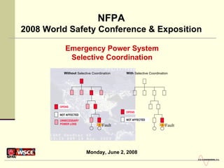
- 1. Emergency Power System Selective Coordination NFPA 2008 World Safety Conference & Exposition Monday, June 2, 2008
- 4. Emergency Power System Selective Coordination What is Selective Coordination?
- 6. Emergency Power System Selective Coordination What is Selective Coordination? Without Selective Coordination With Selective Coordination OPENS NOT AFFECTED UNNECESSARY POWER LOSS OPENS NOT AFFECTED Fault Fault
- 10. System Protection vs. Selectivity An Overcurrent Protective Device Coordination Study evaluates the selection of devices and determines proper settings and ratings for protection AND selectivity Emergency Power System Selective Coordination What are some of the challenges? Protection : To disconnect faulted equipment from the system BEFORE damage occurs [requires FAST and SENSITIVE tripping] Selectivity : Requires some devices employ TIME DELAY tripping or HIGHER activation (pickup) levels [Time delays are dependent on location in system] Can be contradicting objectives
- 12. Overload vs. Fault Emergency Power System Selective Coordination What are some of the challenges? Overload – operation of equip in excess of normal, full load rating, or ampacity of conductor causing damage or dangerous overheating Typical range: 101% < I < 250% full load rating Fault – an unintentional and undesirable conducting path in an electrical power system. Can take many forms; 3L, 3i0, LL, LL-G, L-G Typical range: I > 250% full load rating
- 13. Phase vs. Ground Fault Emergency Power System Selective Coordination What are some of the challenges? Phase Protection : OL or OC, LL faults, 3ph faults, usually of higher current levels GF Protection : L-G faults, LL-G, 3ph-G faults GFP: (Art. 100) – system intended to provide protection of equipment from damaging L-G fault currents by disconnecting all ungrounded conductors of faulted circuit A B C SLG L-L 3ph
- 15. Emergency Power System Selective Coordination What are some of the challenges? ATS Emergency Source N E Normal Source Panel ATS Emergency Source N E Normal Source Panel
- 18. Emergency Power System Selective Coordination The Two Exceptions Exception 2: Two devices of same amp rating in series Exception 1 : Transformer primary and secondary Same Circuit Neither exception reduced life-safety because no additional parts of the electrical system would be shut down unnecessarily Hashed OCPDs do not have to be selectively coordinated Same Circuit 400A OCPD 400A OCPD
- 20. Emergency Power System Selective Coordination Coordination Methods No plotting required Line Side Fuse Load Side Fuse
- 24. Emergency Power System Selective Coordination Coordination Methods Up to where the circuit breakers cross, it is interpreted to be coordinated. See 800A 200A 30A Up to 7600A Up to 1500A X X 1500A 7600A 30A 0.01s 0.1s 800A IT = 10X 200A IT = 10X Circuit Breakers
- 25. Emergency Power System Selective Coordination Coordination Methods Illustrates two instantaneous trip MCCBs: Lineside: 400A (7X IT) Loadside: 100A (Fixed IT) Where they intersect is point of non-coordination 0.01 seconds typically lowest time on TCCs CB IT unlatching times are less than 0.01s Circuit Breakers 0.1s 0.01s 0.001s
- 26. Emergency Power System Selective Coordination Coordination Methods Interpret CB curves: 800A CB does not coordinate with the 200A CB above 5400A, even though the curves do not cross on the plot. 2250A 5400A 800A 30A 200A 0.01s 0.1s 800A 200A 30A Up to 5400A Up to 2250A X X Circuit Breakers
- 27. Emergency Power System Selective Coordination Coordination Methods Circuit Breakers
- 28. Emergency Power System Selective Coordination Coordination Methods Circuit Breakers 1500A Crossing Point Interpreting Curves Max. 2700A: CB Mfg. Coordination Testing CB Manufacturer’s Coordination Tables can help show coordination for higher fault current than simply plotting curves Example: 30A & 200A MCCBs 800A 30A 200A 0.01s 0.1s
- 29. Emergency Power System Selective Coordination Coordination Methods Circuit Breakers Selective coordination for all overcurrents up to the interrupting rating for each circuit breaker Still need to plot curves to ensure there is no crossing of circuit breaker curves. Must have time settings with enough separation. 800A 30A 200A 0.01s 0.1s
- 30. Emergency Power System Selective Coordination Coordination Methods Circuit Breakers - ZSI 1 2 3 X Fault Here 3 2 1 1200A 175A 400A 0.01s 0.1s CB3 Trips Instantaneously Restraint signal Restraint signal
- 31. Fault Here Emergency Power System Selective Coordination Coordination Methods Circuit Breakers - ZSI 1 2 3 X No signal Restraint signal CB2 Trips Instantaneously 3 2 1 1200A 175A 400A 0.01s 0.1s
- 34. Emergency Power System Selective Coordination Coordination Methods Parallel Generators
- 35. Overload protection only. Coordinates with overload characteristics of downstream OCPDs Emergency Power System Selective Coordination Coordination Methods Parallel Generators Normal Source N E N E N E G 87B G Bus differential relaying provides short-circuit protection for bus & generators for bus fault (between CTs) Fuses or CBs selectively coordinated with downstream OCPDs for all overcurrents Emergency Source Bus Differential Relay
- 38. Thank you! www.sandsengineering.com Contact : Douglas R. Strang, Jr., P.E. PO Box 345 Batavia, NY 14021-0345 585-235-3530 [email_address] [email_address] Emergency Power System Selective Coordination