SlideShare une entreprise Scribd logo
1  sur  28
Télécharger pour lire hors ligne
76
1
2
77
Recoolingsystems
Recooling
systems
4
4
4
3
2
2
Recooling systems
Benefits, technical details 78
Mini, cooling output 960/1490 W 80
Mini, cooling output 3000/4500 W 82
Mini, for wall mounting, cooling output 1000/2500/4000 W 84
In floor-standing enclosure, cooling output 2100 to 7700 W 86
In floor-standing enclosure, cooling output 10000 to 25200 W 88
In floor-standing enclosure for oil,
cooling output 2550 to 7900 W 90
In floor-standing enclosure for oil,
cooling output 10600 to 26100 W 92
In TS 8 Top enclosure system, cooling output 6000/7500 W 94
In TS 8 Top enclosure system,
cooling output 10000 to 25000 W 96
In industrial enclosure, cooling output 32 kW to 172 kW 98
Recooling systems can be used in all situations where a high
refrigeration load is required – in process and machine cooling,
media cooling, and for dissipating heat loss from enclosures via
air/water heat exchangers.
Practical example
of a recooling system
The recooling system, as a central unit, is
used to cool a total of three gearbox test
benches at a supplier to the automotive
industry. Prior to delivery, every single
gearbox is subjected to extensive func-
tional and quality testing.
In order to ensure that the test process
runs smoothly, three motors with a total out-
put of 12,000 watts must be cooled effi-
ciently.
The power infeed and control of the test
benches, integrated into five TS 8 enclo-
sures, are cooled by air/water heat
exchangers which are likewise supplied
centrally with the required cooling water via
the recooling system.
One system is used for enclosure, process
and machine cooling: this is one of the key
benefits of using recooling systems.
Recooling system
Gearbox test benches
TS 8 enclosures
Air/water heat exchangers
(roof-mounted and wall-
mounted)
1
2
3
4
78
Recooling systems
Benefits, technical details
Rittal system climate control
Recooling systems ensure centralised, efficient cooling and pro-
vision of the cooling medium (generally water). All cooling tasks on
a system or machine can be solved via a single pipeline system.
Spatial separation between cooling production and process cool-
ing can be achieved with recooling systems.
The range to meet every cooling requirement
Mini recooling systems
with an output range from
960 W to 4,500 W combine a
space-saving, compact struc-
ture with an attractive design.
The wall-mounted units open
up new opportunities by inte-
grating recooling systems into
machine and enclosure hous-
ings without taking up addi-
tional floor space.
Recooling systems integrat-
ed into the TS 8 Top enclo-
sure system
with an output range from
6,000 W to 25,000 W satisfy
demands for a compact design
coupled with the option of inte-
gration into existing TS 8 enclo-
sure combinations.
Recooling systems in a
floor-standing enclosure for
water and oil
with an output range from
2,100 W to 26,100 W are inte-
grated into a stand-alone
enclosure and require only
minimal floor space. The func-
tionally equipped design facili-
tates the cooling of oil and
water.
Special recooling systems
are planned and project man-
aged to customised specifica-
tions by our project engineers.
Implementation of the require-
ments for both cooling and
enclosure technology form the
basis for a recooling system
that is ideally adapted to the
respective requirements.
Recooling systems in an
industrial enclosure
with an output range from
32 kW to 172 kW satisfy
demands for a high cooling
output with optimised space
requirements, whilst their
enclosure design with remov-
able panels ensures easier
access for servicing purposes.
79Rittal system climate control
Recoolingsystems
Application diversity of centralised cooling technology
Benefits:
● Cooling output from
0.96 to 172 kW
● A single system for enclo-
sure cooling, process and
machine cooling, and the
cooling of liquid media
● Integration into bayed
enclosure suites
● Individual project man-
agement
● Commissioning and serv-
icing
Important
● Cooling output calcu-
lated at an ambient tem-
perature of 32°C and an
inlet temperature of 18°C
(water)/20°C (oil)
For planning data
see page 187
or refer to the Internet at
www.rittal.de
Recooling systems are used as
central cooling units for partic-
ularly high heat loads. They
may serve several pieces of
equipment simultaneously, and
are particularly effective in
terms of cooling output.
Enclosure cooling
In conjunction with air/water
heat exchangers, optimum
dissipation of high heat loads
is guaranteed, even under
extreme ambient temperatures
and air contamination levels.
Cooling of liquid media
Direct and indirect cooling of
liquids are the prerequisite for
ensuring necessary machine
precision and speed.
Process cooling
High-quality material process-
ing, such as laser cutting,
necessitates high levels of tem-
perature precision with simulta-
neous cooling of the periph-
eral technology. These require-
ments are met to precision,
thanks to the design of the
cooling system and integral
control systems.
Siting conditions
Unity with enclosures
For example, recooling sys-
tems may be connected direct-
ly to a bayed enclosure suite,
providing effective, centralised
cooling for all enclosures and
housings on a machine or
system.
Spatially separated
High heat loads can even be
dissipated in confined and
awkward spaces, thanks to the
spatial separation of the recool-
ing system from the enclo-
sures and machine. In all
cases, as well as enclosure
cooling, cooling water may also
be produced for process and
machine cooling or for cooling
liquid media.
Recooling system
Air/water heat exchanger,
roof-mounted
Air/water heat exchanger,
wall-mounted
Other components,
e.g. machine cooling
1
2
3
4
2
2
1
2
3
3
1
4
Rittal system climate control80
430
1
/2″
Functional description
Mini recooling systems are used to cool
water with an additional additive, and facili-
tate more precise temperature consistency
of the liquid medium.
Recooling system alternatively configured
as a pressure-sealed or open system.
In the pressure-sealed configuration
(XXXX.600), the water circuit is equipped
with a pressure relief valve and automatic
exhaust. In this way, the water volume can
be routed directly to the consumer with the
integral pump, and no additional tank
reservoir is needed.
The Mini recooling systems configured as
an open system (XXXX.610) have a tank
integrated into the recooling system with a
tank volume of 2.5 l.
Technical design:
● Compact, modular structure of the
cooling components on a base plate
designed as a collecting tray.
● Medium-conveying pumps.
● Precise temperature control, based on
microprocessor technology.
● Collective fault signal with floating
contact.
● Application-specific special equipment
available on request.
Supply includes:
Recooling system wired and plumbed
ready for connection, with multilingual
documentation including functional dia-
gram and wiring plans.
Optionally available:
● Upstream pipework, free from
non-ferrous metals
● Ambient temperature control
● More powerful pumps
● Outdoor siting
● Water-cooled condenser
● External sensor
● Special spray finish
● Special voltages
Model No. SK 3318.600 3318.610 3319.600 3319.610
Rated operating voltage V, Hz 230, 50/60
Dimensions in mm
W
H
D
600
400
430
Cooling output at
Tw = 18°C
Tu = 32°C
960 W/1070 W 1490 W/1660 W
Power consumption 630 W/780 W 845 W/1050 W
Rated current max. 4.2 A 5.4 A
Refrigerant R134a / 0.975 kg
Pmax. cooling circuit 25 bar
Temperature range
Environment +5°C to +43°C
Liquid media +10°C to +30°C
Pump capacity See characteristic curve
Tank – Yes – Yes
Tank capacity Pressure-sealed 2.5 l Pressure-sealed 2.5 l
Water connections 2 x 1/2˝ IG
Weight 48 kg 51 kg
Colour RAL 7035
Protection category (electrics) IP 44
Air throughput of fans 900 m3/h
Temperature control Microcontroller control, setting range +10°C to +30°C (factory setting +18°C)
Special voltages and technical modifications available on request.
Front view Side view Rear view
Key to the adjacent drawing:
1. Compressor
5. Condenser
10. Condenser fan
15. Evaporator coil
20. Expansion valve
25. Filter dryer
30. Pressostat
35. Water pump
40. Flow monitor
45. Vent valve
50. Filling
55. Temperature sensor, water
60. Overpressure valve
65. Pressure relief valve
P
5
10 25
20
30
1
15
T
50
55
S
45
40
35
65 60
600
400
20 °C
Layout diagram
Note:
With a lockable external cooling cycle,
a bypass (overpressure valve) should be
provided in the external water pipes.
Recooling systems
Mini, cooling output 960/1490 W
Rittal system climate control 81
Recoolingsystems
Water connections
The water connections, as well
as the fill and drain nozzles, are
mounted at the rear and easily
accessible.
Characteristic curves of pump
Model No. SK
3318.600 / 3318.610 /
3319.600 / 3319.610
60 Hz
64 8 10 12
H
Q
0
10
20
30
40
.
50 Hz
2.50 5.0 7.5 10
0
10
20
30
40
H
Q
.
H = Delivery head H [m]
Q = Delivery flow Q [l/min]
.
Approvals,
see page 18.
Microcontroller
For control of the water temper-
ature and system analysis with
collective fault signal.
Functional diagram
Accessories:
Filter mat, metal filter mat,
see page 182.
The illustration shows units with customer-specific options
Rittal system climate control82
Functional description
Mini recooling systems are used to cool
water with an additional additive, and facili-
tate more precise temperature consistency
of the liquid medium.
The water circuit, designed as a system
that is open to the atmosphere, is equipp-
ed with an integral tank.
All safety components integrated into the
fully hermetic cooling circuit have been
designed to DIN EN 378 and VBG 20. The
modular configuration of the Mini recooling
system means that the operator display for
the microcontroller may be mounted either
on the front or rear.
The fully functional equipment supports
independent siting of the Mini recooling
system at any time.
Technical design:
● Compact, modular configuration of the
cooling components with integral water
tank. Operator display may optionally be
mounted on the front or rear.
● Integral tank level display.
● Medium-conveying pumps.
● Precise temperature control, based on
microprocessor technology.
● Collective fault signal with floating
contact.
● Application-specific special equipment
available on request.
Supply includes:
Recooling system wired and plumbed
ready for connection, with multilingual doc-
umentation including functional diagram
and wiring plans.
Optionally available:
● Upstream pipework, free from
non-ferrous metals
● Ambient temperature control
● More powerful pumps
● Outdoor siting
● Water-cooled condenser
● Water level switch
● External sensor
● Special spray finish
● Special voltages
Model No. SK 3320.600 3334.600
Rated operating voltage V, Hz 400, 3~, 50 / 60
Dimensions in mm
W
H
D
600
680
625
Cooling output at
Tw = 18°C
Tu = 32°C
3000 W 4500 W
Power consumption 1716 W/1953 W 2001 W/2505 W
Rated current max. 3.8 A/3.9 A 4.9 A/5.0 A
Refrigerant R134a
Pmax. cooling circuit 25 bar
Temperature range
Environment +5°C to +43°C
Liquid media +10°C to +30°C
Pump capacity See characteristic curve
Tank Made from stainless steel 1.4301
Tank capacity 30 l
Water connections 2 x 1/2˝ IG
Weight 51 kg 56 kg
Colour RAL 7035
Protection category (electrics) IP 44
Air throughput of fans 1,785 m3/h
Temperature control Microcontroller control, setting range +10°C to +30°C (factory setting +18°C)
Special voltages and technical modifications available on request.
Front view Side view Rear view
Key to the adjacent drawing:
1. Compressor
5. Condenser
10. Condenser fan
15. Evaporator coil
20. Expansion valve
25. Filter dryer
30. Water tank
35. Filling
40. Tank drain
45. Water level switch, optional
50. Temperature sensor
55. Pump
60. Flow monitor
70. Pressostat
P
S
5
10 25
70
1
15
40
50
45
55
35
20
60
30
Layout diagram
600
680
20°C
630
1
/2″
Note:
With a lockable external cooling cycle,
a bypass (overpressure valve) should be
provided in the external water pipes.
Recooling systems
Mini, cooling output 3000/4500 W
Rittal system climate control 83
Recoolingsystems
Enclosure cooling
with air/water heat exchangers
in the output range from
1 – 5 kW.
Characteristic curves of pump
Model No. SK
3320.600 / 3334.600
60 Hz
H
Q
150 30 45 60
0
15
30
45
60
.
50 Hz
0
15
30
45
60
H
Q
150 30 45 60
.
H = Delivery head H [m]
Q = Delivery flow Q [l/min]
.
Approvals,
see page 18.
Metal filter mat
When using recooling systems
in dusty environments.
Functional diagram
Accessories:
Filter mat, metal filter mat,
see page 182.
The illustration shows units with customer-specific options
Rittal system climate control84
Layout diagram
Functional description
Mini recooling systems for wall mounting
are used to cool water with an additional
additive, and facilitate more precise tem-
perature consistency of the liquid medium.
Because the recooling systems may be
mounted on the wall, there is no additional
floor space required.
The recooling systems, designed as an
open system, have a tank with an integral
pump.
All safety components integrated into the
fully hermetic cooling circuit have been
designed to DIN EN 378 and VBG 20.
Technical design:
● Compact and modular configuration of
the cooling components with integral
water tank.
● Application-specific special equipment
available on request.
Supply includes:
Recooling system wired and plumbed
ready for connection, including drilling
template, with multilingual documentation
including functional diagram and wiring
plans.
Optionally available:
● Upstream pipework, free from
non-ferrous metals
● Ambient temperature control
● More powerful pumps
● Outdoor siting
SK 3360.100
Front view Rear viewSide view
SK 3360.250 / SK 3360.400
Key to the adjacent drawing:
1. Compressor
5. Condenser
10. Condenser fan
15. Evaporator coil
20. Expansion valve
25. Filter dryer
30. Water tank
35. Filling
40. Tank drain
45. Water level switch, optional
50. Temperature sensor
55. Pump
60. Flow monitor
70. Pressostat
Model No. SK 3360.100 3360.250 3360.400
Rated operating voltage V, Hz 400, 3~, 50/60
Dimensions in mm
W
H
D
400
950
310
400
1580
290
500
1580
340
Cooling output at
Tw = 18°C
Tu = 32°C
1000 W 2500 W 4000 W
Power consumption 700 W/760 W 1550 W/2000 W 1980 W/2450 W
Rated current max. 2.7 A/3.0 A 3.7 A/3.8 A 3.9 A/4.2 A
Refrigerant R134a
Pmax. cooling circuit 23 bar
Temperature range
Environment +5°C to +43°C
Liquid media +10°C to +30°C
Pump capacity See characteristic curve
Tank PP
Tank capacity 5 l 10 l 15 l
Water connections 2 x 1/2˝ IG
Weight 47 kg 78 kg 99 kg
Colour RAL 7035
Protection category (electrics) IP 44
Air throughput of fans 500 m3/h 710 m3/h 2,000 m3/h
Temperature control Microcontroller control, setting range +10°C to +30°C (factory setting +18°C)
Special voltages and technical modifications available on request.
B
H
T 1/ ″2
B
H
T 1/ ″2
60
55
50
35
40
30
45
15
1
25
20
10
5
P
S
70
Note:
With a lockable external cooling cycle,
a bypass (overpressure valve) should be
provided in the external water pipes.
Service aperture
Service aperture
B = Width
T = Depth
Recooling systems
Mini, for wall mounting, cooling output 1000/2500/4000 W
Rittal system climate control 85
Recoolingsystems
Machine cooling
Integration of the recooling system into
enclosure and machine housings without
the need for additional floor space.
Characteristic curves of pump
Model No. SK
3360.100 / 3360.250 /
3360.400
60 Hz
H
Q
0
10
20
30
40
100 20 30 40
.
50 Hz
H
Q
0
10
20
30
100 20 30 40
.
H = Delivery head H [m]
Q = Delivery flow Q [l/min]
.
Approvals,
see page 18.
Functional diagram
Accessories:
Filter mat, metal filter mat,
see page 182.
The illustration shows units with customer-specific options
Rittal system climate control86
H
B T
86
60
1
Functional description
The recooling systems are integrated into a
stand-alone enclosure and only require
minimal floor space. The spacious design
offers a high degree of flexibility for
customer-specific adaptations.
Technical design:
● Robust industrial standard in 3 enclosure
sizes.
● Identical basic enclosure for oil and
water recooling systems.
● Spare space for the integration of
special equipment.
● Variable air routing is possible via the left
or right-hand side panel.
● Floating contact for collective fault
signal.
● Level monitor.
● Multi-coil vaporiser in the tank.
Supply includes:
Recooling system wired and plumbed
ready for connection, with multilingual doc-
umentation including functional diagram
and wiring plans.
Optionally available:
● Ambient temperature control
● Condenser pressure control at Tu < 15°C
● UL-tested enclosure
● Electrical water level display
● Flow monitor
● Low-pressure monitor
● Hot gas bypass control in the cooling
circuit
● Designed as a once-through cooler
without tank
● More powerful pumps
● Water heater 500 W/1000 W
● Water level switch
● Automatic tank filling
● Fault signal with individual fault
messages
● External sensor
● Manual or automatic bypass
● Bi-frequency components (50/60 Hz)
● Harting connector
● Outdoor siting
● Special spray finish
Model No. SK 3336.100 3336.200 3336.300 3336.500 3336.600 3336.650
Rated operating voltage V, Hz 400, 3~, 50
Dimensions in mm
W
H
D
470
725
540
485
965
650
595
1180
800
Cooling output at
Tw = 18°C
Tu = 32°C
2100 W 2580 W 3360 W 5040 W 6160 W 7700 W
Power consumption 1.5 kW 1.8 kW 2.3 kW 2.9 kW 3.6 kW
Rated current max. 2.8 A 3.5 A 4.2 A 4.9 A 5.7 A
Refrigerant R134a
Pmax. cooling circuit 24 bar
Temperature range
Environment +15°C to +45°C
Liquid media +10°C to +25°C
Pump capacity See characteristic curve
Tank Made from stainless steel 1.4301
Tank capacity 17 l 33 l 57 l
Water connections 3/4˝ IG 1˝ IG
Weight 75 kg 97 kg 99 kg 141 kg 143 kg 147 kg
Colour RAL 7035
Protection category (electrics) IP 54
Air throughput of fans 700 m3/h 1,250 m3/h 1,785 m3/h 3,140 m3/h
Temperature control Electronic control with digital display, setting range +10°C to +25°C (factory setting +18°C)
Delivery times available on request. Special voltages, other frequencies, and technical modifications available on request.
Front view Side view Rear view,
air exhaust
Key to the adjacent drawing:
1. Compressor
5. Condenser
10. Condenser fan
16. Multi-coil vaporiser
19. Capillary tube/expansion valve*
25. Filter dryer
30. Tank
31. Manometer
35. Tank filler
40. Tank drain
46. Level indicator
55. Pump
80. Thermostat
* from SK 3336.500
5
80
1
10
25
35
16
40
46
30
31
55
Layout diagram
Side view
= Water connections1
Note:
With a lockable external cooling cycle,
a bypass (overpressure valve) should be
provided in the external water pipes.
B = Width
T = Depth
Recooling systems
In floor-standing enclosure, cooling output 2100 to 7700 W
Rittal system climate control 87
Recoolingsystems
ENVIRONMENTALLY FRIENDLY
C OO L I N G T E C H N O LO GY
Removable side panel
Air inlet may be on the right or
left by exchanging the side
panel.
Characteristic curves of pump
Model No. SK
3336.100 / 3336.200 / 3336.300 /
3336.500 / 3336.600 / 3336.650
50 Hz
H
Q
20
0
25
30
35
3020 40 50 60
.
H = Delivery head H [m]
Q = Delivery flow Q [l/min]
.
Approvals,
see page 19.
Air routing
Air inlet openings with inte-
grated louvres.
Functional diagram
Accessories:
Metal filter mats, castors,
eyebolts and safety modules
available on request.
The illustration shows units with customer-specific options
Rittal system climate control88
Functional description
The recooling systems are integrated into a
robust industrial housing and require only
minimum floor space as stand-alone
devices. A wide variety of available options
facilitates optimum adaptation of recooling
systems to customer-specific requirements.
Technical design:
● Robust industrial housing in 2 enclosure
sizes.
● Identical basic enclosure for oil and
water recooling systems.
● Integration of application-specific
special equipment on request.
● Variable air routing is possible via the l/h
or r/h side panel.
● Optimum accessibility for servicing
purposes by removing the side panel.
● Floating contact for collective fault
signal.
● Bi-frequency design (50/60 Hz).
● Flow monitor.
Supply includes:
Recooling system wired and plumbed
ready for connection, with multilingual doc-
umentation including functional diagram
and wiring plans.
Optionally available:
● Ambient temperature control
● Condenser pressure control,
at Tu < 15°C
● Electrical water level display
● Hot gas bypass control in the cooling
circuit
● Designed as a once-through cooler
without tank
● More powerful pumps
● Water heater 500 W/1000 W
● Water level switch
● Automatic tank filling
● Fault signal with individual fault mes-
sages
● External sensor
● Manual or automatic bypass
● Harting connector
● Outdoor siting
● Special spray finish
Model No. SK 3336.700 3336.710 3336.720 3336.730 3336.740 3336.750
Rated operating voltage V, Hz 400, 3~, 50/460, 3~, 60
Dimensions in mm
W
H
D
615
1178
1160
715
1178
1360
Cooling output at
Tw = 18°C
Tu = 32°C
10000 W/
12600 W
14350 W/
18700 W
16300 W/
20100 W
18500 W/
22350 W
20900 W/
25400 W
25200 W/
32250 W
Power consumption 3800 W/5300 W 4800 W/6500 W 5300 W/7100 W 6400 W/9000 W 7100 W/9900 W 8100 W/11500 W
Rated current max. 10.6 A/10.8 A 13.1 A/13.3 A 14.1 A/14.3 A 16.2 A/18.4 A 18.2 A/20.4 A 19.7 A/22.4 A
Refrigerant R407C
Pmax. cooling circuit 27 bar
Temperature range
Environment +15°C to +45°C
Liquid media +10°C to +25°C
Pump capacity See characteristic curve
Tank Made from stainless steel 1.4301
Tank capacity 60 l 100 l
Water connections 1˝ IG
Weight 215 kg 225 kg 235 kg 240 kg 250 kg 260 kg
Colour RAL 7035
Protection category (electrics) IP 54
Air throughput of fans 6,280 m3/h 10,880 m3/h
Temperature control Electronic control with digital display, setting range +10°C to +25°C (factory setting +18°C)
Delivery times available on request. Special voltages and technical modifications available on request.
Key to the adjacent drawing:
1. Compressor
5. Condenser
10. Condenser fan
15. Evaporator coil
20. Expansion valve
21. Inspection glass
22. Magnetic valve
23. Liquid collector
25. Filter dryer
30. Tank
31. Manometer
35. Tank filler
40. Tank drain
46. Level indicator
55. Pump
60. Flow monitor
71. Low-pressure switch
72. High-pressure switch
73. Shut-off valve
80. Thermostat
31
5530
35
40
4660
15
2022
21
25
23
5
10
73
1
73
72
80
71
Layout diagram
Front view Side view Rear view
B
H
T
ASSORBIMENTO ALLO SPUNTO
STARTING CURRENT
INTENSITE' DE DEMARRAGE
ANLAUFSTROM
CONSUMO EN ARRANQUE
REFRIGERANTE / QUANTITA'
REFRIGERANT / QUANTITY
FLUIDE FRIGORIFIQUE / CHARGE
KALTEMITTEL / GEWICHT
REFRIGERANTE / CANTIDAD
POTENZA FRIGORIFICA
COOLING CAPACITY
PUISSANCE FRIGORIFIQUE
NUTZKUHLLEISTUNG
POTENCIA FRIGORIFICA
KELVIN s.r.l. - Via E.Fermi - ZAI - 46040 PONTI s/M. - Italia - (+39) 0376 - 809651 - Fax 809648
PESO
WEIGHT
POIDS
GEWICHT
PESO
SERIE / ANNO
SERIAL / YEAR
SERIE / ANNEE
SERIENNUMMER / BAUJAHR
MATRICULA / ANO
PRESSIONE ALLA POMPA
PUMP AVAILABLE PRESSURE
PRESSION DE REFOULEMENT
PUMPENDRUCK
PRESION EN LA BOMBA
ASSORBIMENTO IN MARCIA
RUNNING CURRENT
INTENSITE' EN MARCHE
BETRIEBSSTROM
CONSUMO EN MARCHA
CAPACITA' VASCA
TANK VOLUME
VOLUME CUVE
TANKINHALT
CAPACIDAD DEPOSITO
TENSIONE NOMINALE
NOMINAL VOLTAGE
TENSION NOMINALE
NENNSPANNUNG
ALIMENTACION ELECTRICA
PRESSIONE SONORA
SOUND PRESSURE LEVEL
PRESSION SONORE
SCHALLDRUCKPEGEL
PRESION SONORA
POTENZA ELETTRICA ASSORBITA
POWER CONSUMPTION
PUISSANCE ELECTRIQUE
LEISTUNGSAUFNAHME
POTENCIA ABSORBIDA
MODELLO
MODEL
TYPE
TYP
MODELO
kpa
I
dB(A)
A
A
V-/Hz
Kg
Kg
1˝
Note:
With a lockable external cooling cycle,
a bypass (overpressure valve) should be
provided in the external water pipes.
B = Width, T = Depth
Recooling systems
In floor-standing enclosure, cooling output 10000 to 25200 W
Rittal system climate control 89
Recoolingsystems
ENVIRONMENTALLY FRIENDLY
C OO L I N G T E C H N O LO GY
System cooling
Process-controlled cooling
guarantees the level of preci-
sion required today.
Characteristic curves of pump
Model No. SK
3336.700 / 3336.710 / 3336.720
60 Hz
3520 50 65 80
H
Q
20
25
30
35
40
.
50 Hz
3520 50 65 80
H
Q
20
25
30
35
40
.
H = Delivery head H [m]
Q = Delivery flow Q [l/min]
.
Approvals,
see page 19.
Functional diagram
The illustration shows units with customer-specific options
60 Hz
4020 60 80 100
H
Q
30
40
50
60
.
50 Hz
4020 60 80 100
H
Q
30
40
50
60
.
Accessories:
Metal filter mat, castors and
safety module
available on request.
Model No. SK
3336.730 / 3336.740 / 3336.750
Rittal system climate control90
H
B T
86
60
1
Functional description
The recooling systems are integrated into a
stand-alone enclosure and require only
minimal floor space. The spacious design
offers a high degree of flexibility for
customer-specific adaptations.
Technical design:
● Robust industrial standard in 2 enclosure
sizes.
● Identical basic enclosure for oil and
water recooling systems.
● Variable air routing is possible via the l/h
or r/h side panel
● High-capacity gear pump
● Floating contact for collective fault signal
● Integration of application-specific
special equipment on request.
Supply includes:
Recooling system wired and plumbed
ready for connection, with multilingual doc-
umentation including functional diagram
and wiring plans.
Optionally available:
● Ambient temperature control
● Condenser pressure control at Tu < 15°C
● UL-tested enclosure
● Electrical level indicator
● Flow monitor
● Low-pressure monitor
● Hot gas bypass control in the cooling
circuit
● Additional oil connections
● More powerful pumps
● Electromagnetic flow monitor
● Bypass valve
● Outdoor siting
● Special spray finish
Model No. SK 3337.200 3337.300 3337.500 3337.600 3337.650
Rated operating voltage V, Hz 400, 3~, 50
Dimensions in mm
W
H
D
485
965
650
595
1180
800
Cooling output with oil ISO VG 32
Toil = 20°C
Tu = 32°C
2550 W 3400 W 5150 W 6700 W 7900 W
Power consumption 1.2 kW 1.6 kW 2.3 kW 2.8 kW 3.6 kW
Rated current max. 3.1 A 3.7 A 4.9 A 5.4 A 5.7 A
Refrigerant R134a
Pmax. cooling circuit 24 bar
Temperature range
Environment +15°C to +45°C
Liquid media +15°C to +35°C
Pump capacity at 10 bar 10 l/min 24 l/min
Optional tank Made from stainless steel 1.4301
Optional tank capacity 33 l 57 l
Connections 3/4˝ IG 1˝ IG
Weight 103 kg 105 kg 148 kg 150 kg 154 kg
Colour RAL 7035
Protection category (electrics) IP 54
Air throughput of fans 1,250 m3/h 1,785 m3/h 3,140 m3/h
Temperature control Electronic control with digital display, setting range +15°C to +35°C (factory setting +20°C)
Delivery times available on request. Special voltages, other frequencies, and technical modifications available on request.
Front view Side view Rear view, air
exhaust
Key to the adjacent drawing:
1. Compressor
5. Condenser
10. Condenser fan
15. Evaporator coil
19. Capillary tube/expansion valve*
25. Filter dryer
31. Manometer
32. Automatic bypass valve
56. Oil pump
57. Motor for oil pump
80. Thermostat
81. Anti-frost thermostat
* from SK 3337.500
Layout diagram
Side view
80
57
31 56
32
1
10
5
15
81
19
25
= Water connections1
B = Width, T = Depth
Recooling systems
In floor-standing enclosure for oil, cooling output 2550 to 7900 W
Rittal system climate control 91
Recoolingsystems
Removable side panel
Air inlet may be on the right or
left by exchanging the side
panel.
Approvals,
see page 19.
Air routing
Air inlet openings with inte-
grated louvres.
Functional diagram
Accessories:
Metal filter mat, castors, and
eyebolts
available on request.
The illustration shows units with customer-specific options
ENVIRONMENTALLY FRIENDLY
C OO L I N G T E C H N O LO GY
Rittal system climate control92
Functional description
The recooling systems are integrated into a
robust industrial housing and require only
minimum floor space as stand-alone
devices. A wide variety of available options
facilitates optimum adaptation of recooling
systems to customer-specific requirements.
Technical design:
● Robust industrial housing in 2 enclosure
sizes.
● Identical basic enclosure for oil and
water recooling systems.
● Variable air routing is possible via the l/h
or r/h side panel.
● Optimum accessibility for servicing
purposes by removing the side panel.
● High-capacity gear pump.
● Floating contact for collective fault
signal.
● Integration of application-specific
special equipment on request.
Supply includes:
Recooling system wired and plumbed
ready for connection, with multilingual doc-
umentation including functional diagram
and wiring plans.
Optionally available:
● Ambient temperature control
● Condenser pressure control,
at Tu < 15°C
● Electrical level indicator
● Flow monitor
● Hot gas bypass control in the cooling
circuit
● Integral tank in stainless steel 1.4301
● Additional oil connections
● More powerful pumps
● Bypass valve
● Outdoor siting
● Special spray finish
Model No. SK 3337.700 3337.710 3337.720 3337.730 3337.740 3337.750
Rated operating voltage V, Hz 400, 3~, 50/460, 3~, 60
Dimensions in mm
W
H
D
615
1178
1160
715
1178
1360
Cooling output with oil ISO VG 32
Toil = 20°C
Tu = 32°C
10600 W/
12000 W
15150 W/
17500 W
17200 W/
20000 W
19250 W/
22500 W
21600 W/
25000 W
26100 W/
30000 W
Power consumption
5300 W/
6300 W
6400 W/
7700 W
7100 W/
8200 W
8700 W/
10300 W
9600 W/
11300 W
10500 W/
13300 W
Rated current max. 12.0 A/12.0 A 15.0 A/15.0 A 16.0 A/16.0 A 19.0 A/20.0 A 21.0 A/22.0 A 22.0 A/24.0 A
Refrigerant R407C
Pmax. cooling circuit 28 bar
Temperature range
Environment +15°C to +45°C
Liquid media +15°C to +35°C
Pump capacity at 10 bar 45 l/min 68 l/min
Optional tank Made from stainless steel 1.4301
Optional tank capacity 60 l 100 l
Connections 1˝ IG
Weight 222 kg 232 kg 242 kg 248 kg 258 kg 268 kg
Colour RAL 7035
Protection category (electrics) IP 54
Air throughput of fans 6,280 m3/h 10,880 m3/h
Temperature control Electronic control with digital display, setting range +15°C to +35°C (factory setting +20°C)
Delivery times available on request. Special voltages, other refrigerants, and technical modifications available on request.
Key to the adjacent drawing:
1. Compressor
5. Condenser
10. Condenser fan
15. Evaporator coil
20. Expansion valve
21. Inspection glass
22. Magnetic valve
23. Liquid collector
25. Filter dryer
31. Manometer
32. Automatic bypass valve
56. Oil pump
57. Motor for oil pump
71. Low-pressure switch
72. High-pressure switch
73. Shut-off valve
80. Thermostat
81. Anti-frost thermostat
73
73
1
10
5
81
80
72
71
56
32
31
57 M
2022
21
25
23
15
Layout diagram
Front view Side view Rear view
B
H
T
ASSORBIMENTO ALLO SPUNTO
STARTING CURRENT
INTENSITE' DE DEMARRAGE
ANLAUFSTROM
CONSUMO EN ARRANQUE
REFRIGERANTE / QUANTITA'
REFRIGERANT / QUANTITY
FLUIDE FRIGORIFIQUE / CHARGE
KALTEMITTEL / GEWICHT
REFRIGERANTE / CANTIDAD
POTENZA FRIGORIFICA
COOLING CAPACITY
PUISSANCE FRIGORIFIQUE
NUTZKUHLLEISTUNG
POTENCIA FRIGORIFICA
KELVIN s.r.l. - Via E.Fermi - ZAI - 46040 PONTI s/M. - Italia - (+39) 0376 - 809651 - Fax 809648
PESO
WEIGHT
POIDS
GEWICHT
PESO
SERIE / ANNO
SERIAL / YEAR
SERIE / ANNEE
SERIENNUMMER / BAUJAHR
MATRICULA / ANO
PRESSIONE ALLA POMPA
PUMP AVAILABLE PRESSURE
PRESSION DE REFOULEMENT
PUMPENDRUCK
PRESION EN LA BOMBA
ASSORBIMENTO IN MARCIA
RUNNING CURRENT
INTENSITE' EN MARCHE
BETRIEBSSTROM
CONSUMO EN MARCHA
CAPACITA' VASCA
TANK VOLUME
VOLUME CUVE
TANKINHALT
CAPACIDAD DEPOSITO
TENSIONE NOMINALE
NOMINAL VOLTAGE
TENSION NOMINALE
NENNSPANNUNG
ALIMENTACION ELECTRICA
PRESSIONE SONORA
SOUND PRESSURE LEVEL
PRESSION SONORE
SCHALLDRUCKPEGEL
PRESION SONORA
POTENZA ELETTRICA ASSORBITA
POWER CONSUMPTION
PUISSANCE ELECTRIQUE
LEISTUNGSAUFNAHME
POTENCIA ABSORBIDA
MODELLO
MODEL
TYPE
TYP
MODELO
kpa
I
dB(A)
A
A
V-/Hz
Kg
Kg
1˝
B = Width
T = Depth
Recooling systems
In floor-standing enclosure for oil, cooling output 10600 to 26100 W
Rittal system climate control 93
Recoolingsystems
System cooling
Process-controlled cooling
guarantees the level of preci-
sion required today.
Approvals,
see page 19.
Functional diagram
The illustration shows units with customer-specific options
Accessories:
Metal filter mats and castors
available on request.
ENVIRONMENTALLY FRIENDLY
C OO L I N G T E C H N O LO GY
Rittal system climate control94
600
2000100
600
3/4˝
Functional description
The recooling systems for cooling water are
integrated into the TS 8 Top enclosure sys-
tem and can therefore be bayed to exist-
ing enclosure suites with little effort. A wide
range of options facilitates optimum adap-
tation of recooling systems in line with
customer-specific requirements.
Technical design:
● Compact structure with control compo-
nents in the front and air intake via the
rear.
● Suitable for bayed siting.
● Special fittings and options available on
request.
● Float-actuated switch as protection
against running dry.
● Floating collective fault signal.
● Equipped with Grundfos pumps and
Siemens components.
● Service accessibility from all sides.
Supply includes:
Recooling system wired and plumbed
ready for connection, with multilingual doc-
umentation including functional diagram
and wiring plans.
Optionally available:
● Tank in stainless steel 1.4301
● Ambient temperature control
● Flow monitor
● Water-cooled condenser
● Refrigerant R134a
● More powerful pumps
● Double pump unit
● Outdoor siting
● Filter mat monitoring
● Fault signal with individual fault mes-
sages
● Hot gas bypass control, cooling circuit
● Automatic filling
● Water micro-filter
● Harting connector
● Base tray
● Special enclosure sizes
● Special spray finish
Model No. SK 3335.060 3335.075
Rated operating voltage V, Hz 400, 3~, 50
Dimensions in mm
W
H
D
600
2000
600
Base/plinth height mm 100
Cooling output at
Tw = 18°C
Tu = 32°C
6000 W 7500 W
Power consumption 2.4 kW 3.0 kW
Rated current max. 7.6 A 8.1 A
Refrigerant R407C
Pmax. cooling circuit 24 bar
Temperature range
Environment +10°C to +43°C
Liquid media +10°C to +30°C
Pump capacity See characteristic curve
Tank Made from PP plastic
Tank capacity 80 l
Water connections 3/4˝ IG
Weight 180 kg 190 kg
Colour RAL 7035
Protection category (electrics) IP 54
Air throughput of fans 4,000 m3/h
Temperature control Electronic control with digital display, setting range +10°C to +30°C (factory setting +18°C)
Delivery times available on request. Special voltages, other frequencies and refrigerants, and technical modifications available on request.
Key to the adjacent drawing:
1. Compressor
5. Condenser
10. Condenser fan
16. Multi-coil vaporiser
20. Expansion valve
21. Inspection glass
23. Liquid collector
25. Filter dryer
30. Tank
31. Manometer
33. Fixed pump bypass
35. Tank filler
40. Tank drain
45. Level switch
55. Pump
70. Pressostat
80. Thermostat
Layout diagram
Front view Side view Rear view
Note:
With a lockable external cooling cycle,
a bypass (overpressure valve) should be
provided in the external water pipes.
31
33
40
5530
80
45
16
35
20
21
70
1
25
23
5
10
Recooling systems
In TS 8 Top enclosure system, cooling output 6000/7500 W
Rittal system climate control 95
Recoolingsystems
Controller
The electronic controller is
used for monitoring functions
and displaying system mes-
sages.
Characteristic curve of pump
Model No. SK
3335.060 / 3335.075
50 Hz
H = Delivery head H [m]
Q = Delivery flow Q [l/min]
3020 40 50 60
H
Q
12
16
20
24
28
.
.
Approvals,
see page 19.
Functional diagram
The illustration shows units with customer-specific options
Accessories:
Metal filter mat and safety
module
available on request.
ENVIRONMENTALLY FRIENDLY
C OO L I N G T E C H N O LO GY
Rittal system climate control96
Functional description
The recooling systems for cooling water are
integrated into the TS 8 Top enclosure sys-
tem and can therefore be bayed to exist-
ing enclosure suites with little effort. A wide
range of options facilitates optimum adap-
tation of recooling systems in line with
customer-specific requirements.
Technical design:
● Compact structure with control compo-
nents in the front and air intake via the
rear.
● Suitable for bayed siting.
● Special fittings and options available on
request.
● Float-actuated switch as protection
against running dry.
● Floating collective fault signal.
● Magnetic valve in the cooling circuit.
● Equipped with Grundfos pumps and
Siemens components.
● Service accessibility from all sides.
Supply includes:
Recooling system wired and plumbed
ready for connection, with multilingual doc-
umentation including functional diagram
and wiring plans.
Optionally available:
● Tank in stainless steel 1.4301
● Ambient temperature control
● More powerful pumps
● Flow monitor
● Water-cooled condenser
● Refrigerant R134a
● Double pump unit
● Outdoor siting
● Filter mat monitoring
● Fault signal with individual fault mes-
sages
● Hot gas bypass control, cooling circuit
● Automatic filling
● Water micro-filter
● Harting connector
● Base tray
● Special enclosure sizes
● Special spray finish
Model No. SK 3335.100 3335.120 3335.150 3335.200 3335.250
Rated operating voltage V, Hz 400, 3 ~, 50
Dimensions in mm
W
H
D
800
2000
600
1200
2000
600
Base/plinth height mm 100
Cooling output at
Tw = 18°C
Tu = 32°C
10000 W 12000 W 15000 W 20000 W 25000 W
Power consumption 4.0 kW 4.8 kW 6.0 kW 8.0 kW 10.0 kW
Rated current max. 12.5 A 17.3 A 18.5 A 23.5 A 27.5 A
Refrigerant R407C
Pmax. cooling circuit 24 bar
Temperature range
Environment +10°C to +43°C
Liquid media +10°C to +30°C
Pump capacity See characteristic curve
Tank Made from PP plastic
Tank capacity 120 l 240 l
Water connections 3/4˝ IG 1˝ IG
Weight 250 kg 270 kg 380 kg 530 kg 560 kg
Colour RAL 7035
Protection category (electrics) IP 54
Air throughput of fans 6,000 m3/h 8,000 m3/h
Temperature control Electronic control with digital display, setting range +10°C to +30°C (factory setting +18°C)
Delivery times available on request. Special voltages, other frequencies, and technical modifications available on request.
Front view Side view Rear view
Key to the adjacent drawing:
1. Compressor
5. Condenser
10. Condenser fan
16. Multi-coil vaporiser
20. Expansion valve
21. Inspection glass
23. Liquid collector
25. Filter dryer
30. Tank
31. Manometer
33. Fixed pump bypass
35. Tank filler
40. Tank drain
45. Level switch
55. Pump
70. Pressostat
80. Thermostat
Layout diagram
Front view
1200
2000100
800
2000100
600
31
33
40
5530
80
45
16
35
20
21
70
1
25
23
5
10
Note:
With a lockable external cooling cycle,
a bypass (overpressure valve) should be
provided in the external water pipes.
Water connections
Recooling systems
In TS 8 Top enclosure system, cooling output 10 to 25 kW
Rittal system climate control 97
Recoolingsystems
Double pump unit
In addition to the standard
pump, an extra pump is
installed for redundancy pur-
poses.
Characteristic curves of pump
Model No. SK
50 Hz 3335.200 / 3335.250
6030 90 120 150
H
Q
20
26
32
38
44
50
.
50 Hz 3335.100 / 3335.120 /
3335.150
3020 40 50 60
H
Q
20
26
32
38
44
50
.
H = Delivery head H [m]
Q = Delivery flow Q [l/min]
.
Functional diagram
Accessories:
Metal filter mat and safety
module
available on request.
The illustration shows units with customer-specific options
Approvals,
see page 19.
ENVIRONMENTALLY FRIENDLY
C OO L I N G T E C H N O LO GY
Rittal system climate control98
H
B T
TH BH
B
T
RITTAL - WerkRITTAL - Werk
Rudolf Loh Gmbh & Co.KGRudolf Loh Gmbh & Co.KG
Auf dem StuetzelbergAuf dem Stuetzelberg
35745 Herbon35745 Herbon
R
STARTINGSTARTING
CURRENTCURRENT
ANLAUFSTROMANLAUFSTROM
TANKTANK
VOLUMEVOLUME
TANKINHALTTANKINHALT
PUMPPUMP
AVAILABLEAVAILABLE
PRESSUREPRESSURE
COOLINGCOOLING
CAPACITYCAPACITY
NUTZKUHLLEINUTZKUHLLEI
SOUNDSOUND
PRESSUREPRESSURE
LEVELLEVEL
POWERPOWER
CONSUMPTIONCONSUMPTION
LEISTUNGSAUFNLEISTUNGSAUFN
WEIWEI
GHTGHT
GEWGEW
REFRIGERANT/QREFRIGERANT/Q
UANTITYUANTITY
KALTEMITTEL/GKALTEMITTEL/G
RUNNINGRUNNING
CURRENTCURRENT
BETRIEBSSTROBETRIEBSSTRO
NOMINALNOMINAL
VOLTAGEVOLTAGE
NENNSPANNUNENNSPANNU
SERIAL/YEARSERIAL/YEAR
SERIENNUMMESERIENNUMME
R/BAUJAHRR/BAUJAHR
MODMOD
ELEL
TYPTYP
Functional description
The enclosures consist of a frame structure
with removable panels for easier access in
case of servicing. The enclosure design is
ideal for industrial applications, thanks to
the robust profile. The recooling system
may be adapted to specific customer
applications via the integration of special
equipment.
Technical design:
● Robust industrial enclosure.
● Optimum service accessbility by remov-
ing the panels.
● Floating contact for collective fault
signal.
● With shell-and-tube evaporator, without
tank (SK 3339.300 – .500).
● Special application-specific equipment
may be integrated on request.
Supply includes:
Recooling system wired and plumbed
ready for connection, with multilingual doc-
umentation including functional diagram
and wiring plans.
Optionally available:
● Ambient temperature control
● Condenser pressure control,
at Tu < 15°C
● Flow monitor
● More powerful pumps
● Water heater 500 W/1000 W
● Bypass
● Automatic tank filling
● Additional water connections
● Outdoor siting
● Special spray finish
Additionally for
SK 3339.400 / SK 3339.500:
● Radial fan for connecting to an external
air duct.
Model No. SK 3339.100 3339.200 3339.300 3339.400 3339.500
Rated operating voltage V, Hz 400, 3~, 50/460, 3~, 60 400, 3~, 50
Dimensions in mm
W
H
D
815
1400
1560
1550
2000
2500
1630
2200
3400
Cooling output at
Tw = 18°C
Tu = 32°C
32025 W/
38430 W
36225 W/
43480 W
66700 W 75900 W 172200 W
Power consumption 15900 W 17600 W 27000 W 28300 W 61000 W
Rated current max. 24.4 A 26.9 A 67 A 74 A 108 A
Refrigerant R407C
Pmax. cooling circuit 28 bar
Temperature range
Environment +15°C to +45°C
Liquid media +10°C to +25°C
Pump capacity See characteristic curve
Tank Made from stainless steel 1.4301
Tank capacity 150 l Pressure-sealed
Water connections 11/4˝ IG 2˝ IG 3˝ IG
Weight 280 kg 300 kg 800 kg 850 kg 2,100 kg
Colour RAL 7035
Protection category (electrics) IP 44
Air throughput of fans 18,000 m3/h 32,000 m3/h 48,000 m3/h
Temperature control Electronic control with digital display, setting range +10°C to +25°C (factory setting +18°C)
Delivery times available on request. Special voltages, other frequencies and refrigerants, and technical modifications available on request.
Front view Rear view
Key to the adjacent drawing:
1. Compressor
5. Condenser
10. Condenser fan
15. Evaporator coil/shell-and-tube
evaporator without tank
20. Expansion valve
21. Inspection glass
22. Magnetic valve
23. Liquid collector
25. Filter dryer
30. Tank
31. Manometer
35. Tank filler
40. Tank drain
46. Level indicator
55. Pump
60. Flow monitor
71. Low-pressure switch
72. High-pressure switch
73. Shut-off valve
80. Thermostat
60
40
46
35
30
55
31
71
80
72
73
73
1
5
10
23
21
22 20
15
25
Layout diagram SK 3339.100*
Side view
SK 3339.300 / SK 3339.400
Front view Rear viewSide view
SK 3339.500
Front view Rear viewSide view
SK 3339.100 / SK 3339.200
Note:
With a lockable external cooling cycle,
a bypass (overpressure valve) should be
provided in the external water pipes.
* Layout diagram SK 3339.200 – .500 available on request.
B = Width
T = Depth
Recooling systems
In industrial enclosure, cooling output 32 kW to 172 kW
Rittal system climate control 99
Recoolingsystems
The recooling system may be
adapted to specific customer
applications on request, via the
integration of special equip-
ment.
Characteristic curves of pump
Model No. SK
60 Hz 3339.100 / .200
907050 110 150130 170
H
Q
35.0
37.5
40.0
42.5
45.0
.
50 Hz 3339.100 / .200
8050 110 140 170
H
Q
25
30
35
40
.
H = Delivery head H [m]
Q = Delivery flow Q [l/min]
.
Functional diagram
Accessories:
Metal filter mat
available on request.
The illustration shows units with customer-specific options
Approvals,
see page 20.
50 Hz 3339.300 / .400
1000 200 300 400
H
Q
18
23
28
33
38
.
50 Hz 3339.500
0 200 400 600 800
H
Q
20
25
30
35
40
.
ENVIRONMENTALLY FRIENDLY
C OO L I N G T E C H N O LO GY
100 Rittal system climate control
Liquid cooling
High performance for CPUs, power packs
and disk drives by cooling directly at the
area where heat is generated. The distribu-
tor pipes for inlet and return lines for tar-
geted, reliable liquid cooling may be inte-
grated into all standard rack systems.
They are linked to an external, central
recooling unit which also controls the inlet
temperature. The drip-free quick-release
coupling ensures an extremely high level of
operational reliability. Monitoring of the sys-
tem functions is performed by the tried-
and-trusted Rittal CMC module.
There are 2 complete basic packages
available for retro-fitting for different enclo-
sure heights.
Package 1
for enclosure height 1200 mm, 24 U
Supply includes:
Recooling system
Water infeed
Connection system, non-return valve and
10 m hose, 1/2˝, fittings, filter, vent valve
Water distribution
Cooling circuit distributor for 20 CPU
cooling circuits, vent valve, 40 bulkhead
couplings, 50 m distributor hose, 6 mm
Package 2
for enclosure height 2000 mm, 42 U
Supply includes:
Recooling system
Water infeed
Connection system, non-return valve and
10 m hose, 1/2˝, fittings, filter, vent valve
Water distribution
Cooling circuit distributor for 40 CPU
cooling circuits, vent valve, 80 bulkhead
couplings, 100 m distributor hose, 6 mm
Model No. SK 3301.810 Model No. SK 3301.820
Supply includes:
Heat sink with retaining brackets, bulkhead coupling and bulkhead connector for
computer housing, coupling sleeve and connector sleeve for connection hose to cooling
circuit distributor. Other cooling systems available on request.
Note on enquiries and advice:
Please tell us which package you are interested in, the number of
CPU cooling circuits, and the type of CPUs.
CPU:
Athlon, Opteron, Xeon, P4, other.
Quantity Packages
Package 1
Package 2
CPU cooling circuits
CPU cooling circuit
101Rittal system climate control
Power Cooling System PCS
CPU liquid cooling
PowerCoolingSystemPCS
High performance
with liquid
cooling . . .
Today’s modern processors
necessitate cooling of approxi-
mately 70 W/cm2. This specific
thermal output is the equiva-
lent of between four and eight
cooker hobs. This stretches
heat dissipation via air to its
physical limitations.
There is also the problem of
substantial noise generation
from the high fan speeds and
the fast airflow.
Compared with air, liquid is
capable of absorbing and dis-
sipating approximately one
thousand times more heat in a
targeted manner away from the
high-performance compo-
nents. What is more, it does so
without any noise generation.
Rittal PCS – the liquid cooling
concept – offers the electronic
performance of the future
● with powerful added output
● with crucial added safety
● with significantly reduced
costs
There is one CPU cooling
circuit available per U.
With the Power Rack System PSR based on flexRack (i) the power
supply, cable management and liquid cooling are integrated
directly into the vertical rack section.
102
Recooling systems
Project planning examples
Effective cooling of machines, processes
and control cabinets via centralised provi-
sion of the cooling liquid. Four examples of
Rittal recooling systems in different output
categories and design lines:
Example 2
Test laboratory
Every single product is subjected to in-
depth functional and quality testing at the
in-house test laboratory. In order to ensure
that the test process runs smoothly, the
control cabinets are cooled via air/water
heat exchangers, and the three test
benches are supplied with the required
cooling water in line with requirements.
These diverse cooling tasks are performed
by the recooling system integrated into the
TS 8 Top enclosure system. Visually, they
form a single unit with the TS 8 control
cabinets.
Example 3
Control room
In conjunction with air/water heat exchang-
ers, the server and network enclosures
installed in the production control room are
cooled by a Mini recooling system.
Without contaminating the room air, and for
optimum dissipation of the heat loss gener-
ated by the recooling systems, this is
installed outside of the production control
room.
Example 1
Production line
High-quality material processing requires a
high degree of temperature precision with
simultaneous cooling of the peripheral
technology. This task – the cost-effective
cooling of various equipment in the pro-
duction line – is performed centrally by the
recooling system in an industrial enclosure.
It supplies the machine and process cool-
ing with the required cooling water, as well
as the control cabinets via air/water heat
exchangers.
Control
room
Production line
Recoolingsystems
Example 4
Tool production
The heat loss generated during tool
machining (e.g. by water-cooled motor
spindles with high-frequency drives) must
be dissipated efficiently. This task is per-
formed by a wall-mounted Mini recooling
system which at the same time ensures
cooling of the control unit, likewise inte-
grated into the machine.
Test laboratory
Tool production

Contenu connexe

Similaire à Rittal - Re-Cooling - Chiller Ürünleri

Crac precision climate_control_units_for_data_centres
Crac precision climate_control_units_for_data_centresCrac precision climate_control_units_for_data_centres
Crac precision climate_control_units_for_data_centresEeu SC
 
Rittal Isı Değiştiricileri 104 129
Rittal Isı Değiştiricileri 104 129Rittal Isı Değiştiricileri 104 129
Rittal Isı Değiştiricileri 104 129erdinc klima
 
Rittal - İklimlendirme ve Soğutma Ürünleri 024 075
Rittal - İklimlendirme ve Soğutma Ürünleri 024 075Rittal - İklimlendirme ve Soğutma Ürünleri 024 075
Rittal - İklimlendirme ve Soğutma Ürünleri 024 075erdinc klima
 
Sb ls freecool-screw-inverter_1.2_en
Sb ls freecool-screw-inverter_1.2_enSb ls freecool-screw-inverter_1.2_en
Sb ls freecool-screw-inverter_1.2_enYury Naumov
 
Water Cooled Portable Air Conditioners
Water Cooled Portable Air ConditionersWater Cooled Portable Air Conditioners
Water Cooled Portable Air ConditionersMead O'Brien, Inc.
 
Lcp hybrid –_effi_cient_performance_with_heat_pipe_technology
Lcp hybrid –_effi_cient_performance_with_heat_pipe_technologyLcp hybrid –_effi_cient_performance_with_heat_pipe_technology
Lcp hybrid –_effi_cient_performance_with_heat_pipe_technologyEeu SC
 
Rittal Pano Isıtıcıları
Rittal Pano IsıtıcılarıRittal Pano Isıtıcıları
Rittal Pano Isıtıcılarıerdinc klima
 
Load Match Next Generation
Load Match Next GenerationLoad Match Next Generation
Load Match Next Generationkiakaha
 
Rittal - İklimlendirme ve Soğutma Ürünleri 144 161
Rittal - İklimlendirme ve Soğutma Ürünleri 144 161 Rittal - İklimlendirme ve Soğutma Ürünleri 144 161
Rittal - İklimlendirme ve Soğutma Ürünleri 144 161 erdinc klima
 
Sb ls scroll-uc-ii_ver.1.0_en
Sb ls scroll-uc-ii_ver.1.0_enSb ls scroll-uc-ii_ver.1.0_en
Sb ls scroll-uc-ii_ver.1.0_enYury Naumov
 
Sb delta cw-cwu-ver.3.0_en
Sb delta cw-cwu-ver.3.0_enSb delta cw-cwu-ver.3.0_en
Sb delta cw-cwu-ver.3.0_enYury Naumov
 
Rittal top therm_chiller
Rittal top therm_chillerRittal top therm_chiller
Rittal top therm_chillerEeu SC
 
Sb ls screw-inverter_ver.3.0_en
Sb ls screw-inverter_ver.3.0_enSb ls screw-inverter_ver.3.0_en
Sb ls screw-inverter_ver.3.0_enYury Naumov
 
Uscatoare cu ciclu frigorifer CECCATO
Uscatoare cu ciclu frigorifer CECCATOUscatoare cu ciclu frigorifer CECCATO
Uscatoare cu ciclu frigorifer CECCATOColinGroup Craiova
 
Zeus superior k w export manual tehnic - st-zkw ed 12-07 (en)
Zeus superior k w export   manual tehnic - st-zkw ed 12-07 (en)Zeus superior k w export   manual tehnic - st-zkw ed 12-07 (en)
Zeus superior k w export manual tehnic - st-zkw ed 12-07 (en)Costel Sirghi
 

Similaire à Rittal - Re-Cooling - Chiller Ürünleri (20)

P y un50_00
P y un50_00P y un50_00
P y un50_00
 
G y un50_00
G y un50_00G y un50_00
G y un50_00
 
Crac precision climate_control_units_for_data_centres
Crac precision climate_control_units_for_data_centresCrac precision climate_control_units_for_data_centres
Crac precision climate_control_units_for_data_centres
 
Rittal Isı Değiştiricileri 104 129
Rittal Isı Değiştiricileri 104 129Rittal Isı Değiştiricileri 104 129
Rittal Isı Değiştiricileri 104 129
 
Rittal - İklimlendirme ve Soğutma Ürünleri 024 075
Rittal - İklimlendirme ve Soğutma Ürünleri 024 075Rittal - İklimlendirme ve Soğutma Ürünleri 024 075
Rittal - İklimlendirme ve Soğutma Ürünleri 024 075
 
Sb ls freecool-screw-inverter_1.2_en
Sb ls freecool-screw-inverter_1.2_enSb ls freecool-screw-inverter_1.2_en
Sb ls freecool-screw-inverter_1.2_en
 
Water Cooled Portable Air Conditioners
Water Cooled Portable Air ConditionersWater Cooled Portable Air Conditioners
Water Cooled Portable Air Conditioners
 
Lcp hybrid –_effi_cient_performance_with_heat_pipe_technology
Lcp hybrid –_effi_cient_performance_with_heat_pipe_technologyLcp hybrid –_effi_cient_performance_with_heat_pipe_technology
Lcp hybrid –_effi_cient_performance_with_heat_pipe_technology
 
Rittal Pano Isıtıcıları
Rittal Pano IsıtıcılarıRittal Pano Isıtıcıları
Rittal Pano Isıtıcıları
 
Industrial
IndustrialIndustrial
Industrial
 
Load Match Next Generation
Load Match Next GenerationLoad Match Next Generation
Load Match Next Generation
 
Rittal - İklimlendirme ve Soğutma Ürünleri 144 161
Rittal - İklimlendirme ve Soğutma Ürünleri 144 161 Rittal - İklimlendirme ve Soğutma Ürünleri 144 161
Rittal - İklimlendirme ve Soğutma Ürünleri 144 161
 
Sb ls scroll-uc-ii_ver.1.0_en
Sb ls scroll-uc-ii_ver.1.0_enSb ls scroll-uc-ii_ver.1.0_en
Sb ls scroll-uc-ii_ver.1.0_en
 
Ersr y un50_00
Ersr y un50_00Ersr y un50_00
Ersr y un50_00
 
Sb delta cw-cwu-ver.3.0_en
Sb delta cw-cwu-ver.3.0_enSb delta cw-cwu-ver.3.0_en
Sb delta cw-cwu-ver.3.0_en
 
Cooling_present(EN) - .pdf
Cooling_present(EN) - .pdfCooling_present(EN) - .pdf
Cooling_present(EN) - .pdf
 
Rittal top therm_chiller
Rittal top therm_chillerRittal top therm_chiller
Rittal top therm_chiller
 
Sb ls screw-inverter_ver.3.0_en
Sb ls screw-inverter_ver.3.0_enSb ls screw-inverter_ver.3.0_en
Sb ls screw-inverter_ver.3.0_en
 
Uscatoare cu ciclu frigorifer CECCATO
Uscatoare cu ciclu frigorifer CECCATOUscatoare cu ciclu frigorifer CECCATO
Uscatoare cu ciclu frigorifer CECCATO
 
Zeus superior k w export manual tehnic - st-zkw ed 12-07 (en)
Zeus superior k w export   manual tehnic - st-zkw ed 12-07 (en)Zeus superior k w export   manual tehnic - st-zkw ed 12-07 (en)
Zeus superior k w export manual tehnic - st-zkw ed 12-07 (en)
 

Plus de erdinc klima

Tlc temperature-limit-controller
Tlc temperature-limit-controllerTlc temperature-limit-controller
Tlc temperature-limit-controllererdinc klima
 
T ex universal-controller
T ex universal-controllerT ex universal-controller
T ex universal-controllererdinc klima
 
Tcx 14062-hrv-isi-ger-havalandirma-kontroloru
Tcx 14062-hrv-isi-ger-havalandirma-kontroloruTcx 14062-hrv-isi-ger-havalandirma-kontroloru
Tcx 14062-hrv-isi-ger-havalandirma-kontroloruerdinc klima
 
Tcx 12062-universal-controller
Tcx 12062-universal-controllerTcx 12062-universal-controller
Tcx 12062-universal-controllererdinc klima
 
Tcx2 40863 u-opa2-universal-controller
Tcx2 40863 u-opa2-universal-controllerTcx2 40863 u-opa2-universal-controller
Tcx2 40863 u-opa2-universal-controllererdinc klima
 
Tci universal-controller
Tci universal-controllerTci universal-controller
Tci universal-controllererdinc klima
 
M6000 t1-t2-an-air-conditione-controller
M6000 t1-t2-an-air-conditione-controllerM6000 t1-t2-an-air-conditione-controller
M6000 t1-t2-an-air-conditione-controllererdinc klima
 
Fcc 01 free-coolin-controller
Fcc 01 free-coolin-controllerFcc 01 free-coolin-controller
Fcc 01 free-coolin-controllererdinc klima
 
Ec 300-energy-controller
Ec 300-energy-controllerEc 300-energy-controller
Ec 300-energy-controllererdinc klima
 
Tcy3 universa-controller
Tcy3 universa-controllerTcy3 universa-controller
Tcy3 universa-controllererdinc klima
 
Kontrol vanası ve servomotorlar watts v2 bm-v3bm-lineer-vanalar
Kontrol vanası ve servomotorlar watts v2 bm-v3bm-lineer-vanalarKontrol vanası ve servomotorlar watts v2 bm-v3bm-lineer-vanalar
Kontrol vanası ve servomotorlar watts v2 bm-v3bm-lineer-vanalarerdinc klima
 
Kontrol vanası ve servomotorlar gruner kureselmotorluvanalar225serisi
Kontrol vanası ve servomotorlar gruner kureselmotorluvanalar225serisiKontrol vanası ve servomotorlar gruner kureselmotorluvanalar225serisi
Kontrol vanası ve servomotorlar gruner kureselmotorluvanalar225serisierdinc klima
 
Kontrol vanası ve servomotorlar gruner kuresel motorluvanalar224-235serisi
Kontrol vanası ve servomotorlar gruner kuresel motorluvanalar224-235serisiKontrol vanası ve servomotorlar gruner kuresel motorluvanalar224-235serisi
Kontrol vanası ve servomotorlar gruner kuresel motorluvanalar224-235serisierdinc klima
 
Kontrol vanası ve servomotorlar esbe rotary-vana-motorlari-90-serisi
Kontrol vanası ve servomotorlar esbe rotary-vana-motorlari-90-serisiKontrol vanası ve servomotorlar esbe rotary-vana-motorlari-90-serisi
Kontrol vanası ve servomotorlar esbe rotary-vana-motorlari-90-serisierdinc klima
 
Kontrol vanası ve servomotorlar esbe rotary-kontrol-vanalari-3 f-serisi
Kontrol vanası ve servomotorlar esbe rotary-kontrol-vanalari-3 f-serisiKontrol vanası ve servomotorlar esbe rotary-kontrol-vanalari-3 f-serisi
Kontrol vanası ve servomotorlar esbe rotary-kontrol-vanalari-3 f-serisierdinc klima
 
Kontrol vanası ve servomotorlar esbe lineer-vana-motorlari-ala-serisi
Kontrol vanası ve servomotorlar esbe lineer-vana-motorlari-ala-serisiKontrol vanası ve servomotorlar esbe lineer-vana-motorlari-ala-serisi
Kontrol vanası ve servomotorlar esbe lineer-vana-motorlari-ala-serisierdinc klima
 
Kontrol vanası ve servomotorlar esbe rotary-vana-motorlari-ara600-serisi
Kontrol vanası ve servomotorlar esbe rotary-vana-motorlari-ara600-serisiKontrol vanası ve servomotorlar esbe rotary-vana-motorlari-ara600-serisi
Kontrol vanası ve servomotorlar esbe rotary-vana-motorlari-ara600-serisierdinc klima
 
Duyar Elemanlar St fr ex-donma-termostat
Duyar Elemanlar St fr ex-donma-termostatDuyar Elemanlar St fr ex-donma-termostat
Duyar Elemanlar St fr ex-donma-termostaterdinc klima
 
Duyar Elemanlar Sensi co px300-co-sensor
Duyar Elemanlar Sensi co px300-co-sensorDuyar Elemanlar Sensi co px300-co-sensor
Duyar Elemanlar Sensi co px300-co-sensorerdinc klima
 
Duyar Elemanlar Vector sensorler
Duyar Elemanlar Vector sensorlerDuyar Elemanlar Vector sensorler
Duyar Elemanlar Vector sensorlererdinc klima
 

Plus de erdinc klima (20)

Tlc temperature-limit-controller
Tlc temperature-limit-controllerTlc temperature-limit-controller
Tlc temperature-limit-controller
 
T ex universal-controller
T ex universal-controllerT ex universal-controller
T ex universal-controller
 
Tcx 14062-hrv-isi-ger-havalandirma-kontroloru
Tcx 14062-hrv-isi-ger-havalandirma-kontroloruTcx 14062-hrv-isi-ger-havalandirma-kontroloru
Tcx 14062-hrv-isi-ger-havalandirma-kontroloru
 
Tcx 12062-universal-controller
Tcx 12062-universal-controllerTcx 12062-universal-controller
Tcx 12062-universal-controller
 
Tcx2 40863 u-opa2-universal-controller
Tcx2 40863 u-opa2-universal-controllerTcx2 40863 u-opa2-universal-controller
Tcx2 40863 u-opa2-universal-controller
 
Tci universal-controller
Tci universal-controllerTci universal-controller
Tci universal-controller
 
M6000 t1-t2-an-air-conditione-controller
M6000 t1-t2-an-air-conditione-controllerM6000 t1-t2-an-air-conditione-controller
M6000 t1-t2-an-air-conditione-controller
 
Fcc 01 free-coolin-controller
Fcc 01 free-coolin-controllerFcc 01 free-coolin-controller
Fcc 01 free-coolin-controller
 
Ec 300-energy-controller
Ec 300-energy-controllerEc 300-energy-controller
Ec 300-energy-controller
 
Tcy3 universa-controller
Tcy3 universa-controllerTcy3 universa-controller
Tcy3 universa-controller
 
Kontrol vanası ve servomotorlar watts v2 bm-v3bm-lineer-vanalar
Kontrol vanası ve servomotorlar watts v2 bm-v3bm-lineer-vanalarKontrol vanası ve servomotorlar watts v2 bm-v3bm-lineer-vanalar
Kontrol vanası ve servomotorlar watts v2 bm-v3bm-lineer-vanalar
 
Kontrol vanası ve servomotorlar gruner kureselmotorluvanalar225serisi
Kontrol vanası ve servomotorlar gruner kureselmotorluvanalar225serisiKontrol vanası ve servomotorlar gruner kureselmotorluvanalar225serisi
Kontrol vanası ve servomotorlar gruner kureselmotorluvanalar225serisi
 
Kontrol vanası ve servomotorlar gruner kuresel motorluvanalar224-235serisi
Kontrol vanası ve servomotorlar gruner kuresel motorluvanalar224-235serisiKontrol vanası ve servomotorlar gruner kuresel motorluvanalar224-235serisi
Kontrol vanası ve servomotorlar gruner kuresel motorluvanalar224-235serisi
 
Kontrol vanası ve servomotorlar esbe rotary-vana-motorlari-90-serisi
Kontrol vanası ve servomotorlar esbe rotary-vana-motorlari-90-serisiKontrol vanası ve servomotorlar esbe rotary-vana-motorlari-90-serisi
Kontrol vanası ve servomotorlar esbe rotary-vana-motorlari-90-serisi
 
Kontrol vanası ve servomotorlar esbe rotary-kontrol-vanalari-3 f-serisi
Kontrol vanası ve servomotorlar esbe rotary-kontrol-vanalari-3 f-serisiKontrol vanası ve servomotorlar esbe rotary-kontrol-vanalari-3 f-serisi
Kontrol vanası ve servomotorlar esbe rotary-kontrol-vanalari-3 f-serisi
 
Kontrol vanası ve servomotorlar esbe lineer-vana-motorlari-ala-serisi
Kontrol vanası ve servomotorlar esbe lineer-vana-motorlari-ala-serisiKontrol vanası ve servomotorlar esbe lineer-vana-motorlari-ala-serisi
Kontrol vanası ve servomotorlar esbe lineer-vana-motorlari-ala-serisi
 
Kontrol vanası ve servomotorlar esbe rotary-vana-motorlari-ara600-serisi
Kontrol vanası ve servomotorlar esbe rotary-vana-motorlari-ara600-serisiKontrol vanası ve servomotorlar esbe rotary-vana-motorlari-ara600-serisi
Kontrol vanası ve servomotorlar esbe rotary-vana-motorlari-ara600-serisi
 
Duyar Elemanlar St fr ex-donma-termostat
Duyar Elemanlar St fr ex-donma-termostatDuyar Elemanlar St fr ex-donma-termostat
Duyar Elemanlar St fr ex-donma-termostat
 
Duyar Elemanlar Sensi co px300-co-sensor
Duyar Elemanlar Sensi co px300-co-sensorDuyar Elemanlar Sensi co px300-co-sensor
Duyar Elemanlar Sensi co px300-co-sensor
 
Duyar Elemanlar Vector sensorler
Duyar Elemanlar Vector sensorlerDuyar Elemanlar Vector sensorler
Duyar Elemanlar Vector sensorler
 

Dernier

PSCC - Capability Statement Presentation
PSCC - Capability Statement PresentationPSCC - Capability Statement Presentation
PSCC - Capability Statement PresentationAnamaria Contreras
 
Church Building Grants To Assist With New Construction, Additions, And Restor...
Church Building Grants To Assist With New Construction, Additions, And Restor...Church Building Grants To Assist With New Construction, Additions, And Restor...
Church Building Grants To Assist With New Construction, Additions, And Restor...Americas Got Grants
 
TriStar Gold Corporate Presentation - April 2024
TriStar Gold Corporate Presentation - April 2024TriStar Gold Corporate Presentation - April 2024
TriStar Gold Corporate Presentation - April 2024Adnet Communications
 
(Best) ENJOY Call Girls in Faridabad Ex | 8377087607
(Best) ENJOY Call Girls in Faridabad Ex | 8377087607(Best) ENJOY Call Girls in Faridabad Ex | 8377087607
(Best) ENJOY Call Girls in Faridabad Ex | 8377087607dollysharma2066
 
8447779800, Low rate Call girls in Tughlakabad Delhi NCR
8447779800, Low rate Call girls in Tughlakabad Delhi NCR8447779800, Low rate Call girls in Tughlakabad Delhi NCR
8447779800, Low rate Call girls in Tughlakabad Delhi NCRashishs7044
 
Youth Involvement in an Innovative Coconut Value Chain by Mwalimu Menza
Youth Involvement in an Innovative Coconut Value Chain by Mwalimu MenzaYouth Involvement in an Innovative Coconut Value Chain by Mwalimu Menza
Youth Involvement in an Innovative Coconut Value Chain by Mwalimu Menzaictsugar
 
International Business Environments and Operations 16th Global Edition test b...
International Business Environments and Operations 16th Global Edition test b...International Business Environments and Operations 16th Global Edition test b...
International Business Environments and Operations 16th Global Edition test b...ssuserf63bd7
 
8447779800, Low rate Call girls in New Ashok Nagar Delhi NCR
8447779800, Low rate Call girls in New Ashok Nagar Delhi NCR8447779800, Low rate Call girls in New Ashok Nagar Delhi NCR
8447779800, Low rate Call girls in New Ashok Nagar Delhi NCRashishs7044
 
Darshan Hiranandani [News About Next CEO].pdf
Darshan Hiranandani [News About Next CEO].pdfDarshan Hiranandani [News About Next CEO].pdf
Darshan Hiranandani [News About Next CEO].pdfShashank Mehta
 
Ten Organizational Design Models to align structure and operations to busines...
Ten Organizational Design Models to align structure and operations to busines...Ten Organizational Design Models to align structure and operations to busines...
Ten Organizational Design Models to align structure and operations to busines...Seta Wicaksana
 
Innovation Conference 5th March 2024.pdf
Innovation Conference 5th March 2024.pdfInnovation Conference 5th March 2024.pdf
Innovation Conference 5th March 2024.pdfrichard876048
 
8447779800, Low rate Call girls in Uttam Nagar Delhi NCR
8447779800, Low rate Call girls in Uttam Nagar Delhi NCR8447779800, Low rate Call girls in Uttam Nagar Delhi NCR
8447779800, Low rate Call girls in Uttam Nagar Delhi NCRashishs7044
 
Traction part 2 - EOS Model JAX Bridges.
Traction part 2 - EOS Model JAX Bridges.Traction part 2 - EOS Model JAX Bridges.
Traction part 2 - EOS Model JAX Bridges.Anamaria Contreras
 
Call US-88OO1O2216 Call Girls In Mahipalpur Female Escort Service
Call US-88OO1O2216 Call Girls In Mahipalpur Female Escort ServiceCall US-88OO1O2216 Call Girls In Mahipalpur Female Escort Service
Call US-88OO1O2216 Call Girls In Mahipalpur Female Escort Servicecallgirls2057
 
Investment in The Coconut Industry by Nancy Cheruiyot
Investment in The Coconut Industry by Nancy CheruiyotInvestment in The Coconut Industry by Nancy Cheruiyot
Investment in The Coconut Industry by Nancy Cheruiyotictsugar
 
Call Us 📲8800102216📞 Call Girls In DLF City Gurgaon
Call Us 📲8800102216📞 Call Girls In DLF City GurgaonCall Us 📲8800102216📞 Call Girls In DLF City Gurgaon
Call Us 📲8800102216📞 Call Girls In DLF City Gurgaoncallgirls2057
 
Kenya Coconut Production Presentation by Dr. Lalith Perera
Kenya Coconut Production Presentation by Dr. Lalith PereraKenya Coconut Production Presentation by Dr. Lalith Perera
Kenya Coconut Production Presentation by Dr. Lalith Pereraictsugar
 

Dernier (20)

PSCC - Capability Statement Presentation
PSCC - Capability Statement PresentationPSCC - Capability Statement Presentation
PSCC - Capability Statement Presentation
 
Church Building Grants To Assist With New Construction, Additions, And Restor...
Church Building Grants To Assist With New Construction, Additions, And Restor...Church Building Grants To Assist With New Construction, Additions, And Restor...
Church Building Grants To Assist With New Construction, Additions, And Restor...
 
TriStar Gold Corporate Presentation - April 2024
TriStar Gold Corporate Presentation - April 2024TriStar Gold Corporate Presentation - April 2024
TriStar Gold Corporate Presentation - April 2024
 
(Best) ENJOY Call Girls in Faridabad Ex | 8377087607
(Best) ENJOY Call Girls in Faridabad Ex | 8377087607(Best) ENJOY Call Girls in Faridabad Ex | 8377087607
(Best) ENJOY Call Girls in Faridabad Ex | 8377087607
 
8447779800, Low rate Call girls in Tughlakabad Delhi NCR
8447779800, Low rate Call girls in Tughlakabad Delhi NCR8447779800, Low rate Call girls in Tughlakabad Delhi NCR
8447779800, Low rate Call girls in Tughlakabad Delhi NCR
 
Japan IT Week 2024 Brochure by 47Billion (English)
Japan IT Week 2024 Brochure by 47Billion (English)Japan IT Week 2024 Brochure by 47Billion (English)
Japan IT Week 2024 Brochure by 47Billion (English)
 
Youth Involvement in an Innovative Coconut Value Chain by Mwalimu Menza
Youth Involvement in an Innovative Coconut Value Chain by Mwalimu MenzaYouth Involvement in an Innovative Coconut Value Chain by Mwalimu Menza
Youth Involvement in an Innovative Coconut Value Chain by Mwalimu Menza
 
International Business Environments and Operations 16th Global Edition test b...
International Business Environments and Operations 16th Global Edition test b...International Business Environments and Operations 16th Global Edition test b...
International Business Environments and Operations 16th Global Edition test b...
 
8447779800, Low rate Call girls in New Ashok Nagar Delhi NCR
8447779800, Low rate Call girls in New Ashok Nagar Delhi NCR8447779800, Low rate Call girls in New Ashok Nagar Delhi NCR
8447779800, Low rate Call girls in New Ashok Nagar Delhi NCR
 
Darshan Hiranandani [News About Next CEO].pdf
Darshan Hiranandani [News About Next CEO].pdfDarshan Hiranandani [News About Next CEO].pdf
Darshan Hiranandani [News About Next CEO].pdf
 
No-1 Call Girls In Goa 93193 VIP 73153 Escort service In North Goa Panaji, Ca...
No-1 Call Girls In Goa 93193 VIP 73153 Escort service In North Goa Panaji, Ca...No-1 Call Girls In Goa 93193 VIP 73153 Escort service In North Goa Panaji, Ca...
No-1 Call Girls In Goa 93193 VIP 73153 Escort service In North Goa Panaji, Ca...
 
Ten Organizational Design Models to align structure and operations to busines...
Ten Organizational Design Models to align structure and operations to busines...Ten Organizational Design Models to align structure and operations to busines...
Ten Organizational Design Models to align structure and operations to busines...
 
Innovation Conference 5th March 2024.pdf
Innovation Conference 5th March 2024.pdfInnovation Conference 5th March 2024.pdf
Innovation Conference 5th March 2024.pdf
 
8447779800, Low rate Call girls in Uttam Nagar Delhi NCR
8447779800, Low rate Call girls in Uttam Nagar Delhi NCR8447779800, Low rate Call girls in Uttam Nagar Delhi NCR
8447779800, Low rate Call girls in Uttam Nagar Delhi NCR
 
Traction part 2 - EOS Model JAX Bridges.
Traction part 2 - EOS Model JAX Bridges.Traction part 2 - EOS Model JAX Bridges.
Traction part 2 - EOS Model JAX Bridges.
 
Call US-88OO1O2216 Call Girls In Mahipalpur Female Escort Service
Call US-88OO1O2216 Call Girls In Mahipalpur Female Escort ServiceCall US-88OO1O2216 Call Girls In Mahipalpur Female Escort Service
Call US-88OO1O2216 Call Girls In Mahipalpur Female Escort Service
 
Investment in The Coconut Industry by Nancy Cheruiyot
Investment in The Coconut Industry by Nancy CheruiyotInvestment in The Coconut Industry by Nancy Cheruiyot
Investment in The Coconut Industry by Nancy Cheruiyot
 
Call Us 📲8800102216📞 Call Girls In DLF City Gurgaon
Call Us 📲8800102216📞 Call Girls In DLF City GurgaonCall Us 📲8800102216📞 Call Girls In DLF City Gurgaon
Call Us 📲8800102216📞 Call Girls In DLF City Gurgaon
 
Call Us ➥9319373153▻Call Girls In North Goa
Call Us ➥9319373153▻Call Girls In North GoaCall Us ➥9319373153▻Call Girls In North Goa
Call Us ➥9319373153▻Call Girls In North Goa
 
Kenya Coconut Production Presentation by Dr. Lalith Perera
Kenya Coconut Production Presentation by Dr. Lalith PereraKenya Coconut Production Presentation by Dr. Lalith Perera
Kenya Coconut Production Presentation by Dr. Lalith Perera
 

Rittal - Re-Cooling - Chiller Ürünleri

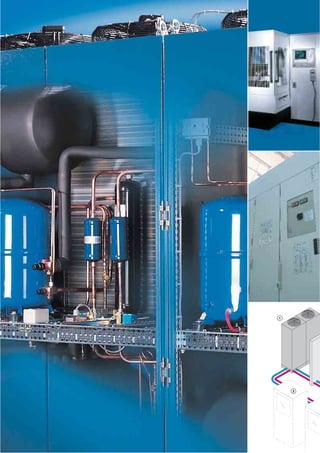
  • 2. 77 Recoolingsystems Recooling systems 4 4 4 3 2 2 Recooling systems Benefits, technical details 78 Mini, cooling output 960/1490 W 80 Mini, cooling output 3000/4500 W 82 Mini, for wall mounting, cooling output 1000/2500/4000 W 84 In floor-standing enclosure, cooling output 2100 to 7700 W 86 In floor-standing enclosure, cooling output 10000 to 25200 W 88 In floor-standing enclosure for oil, cooling output 2550 to 7900 W 90 In floor-standing enclosure for oil, cooling output 10600 to 26100 W 92 In TS 8 Top enclosure system, cooling output 6000/7500 W 94 In TS 8 Top enclosure system, cooling output 10000 to 25000 W 96 In industrial enclosure, cooling output 32 kW to 172 kW 98 Recooling systems can be used in all situations where a high refrigeration load is required – in process and machine cooling, media cooling, and for dissipating heat loss from enclosures via air/water heat exchangers. Practical example of a recooling system The recooling system, as a central unit, is used to cool a total of three gearbox test benches at a supplier to the automotive industry. Prior to delivery, every single gearbox is subjected to extensive func- tional and quality testing. In order to ensure that the test process runs smoothly, three motors with a total out- put of 12,000 watts must be cooled effi- ciently. The power infeed and control of the test benches, integrated into five TS 8 enclo- sures, are cooled by air/water heat exchangers which are likewise supplied centrally with the required cooling water via the recooling system. One system is used for enclosure, process and machine cooling: this is one of the key benefits of using recooling systems. Recooling system Gearbox test benches TS 8 enclosures Air/water heat exchangers (roof-mounted and wall- mounted) 1 2 3 4
  • 3. 78 Recooling systems Benefits, technical details Rittal system climate control Recooling systems ensure centralised, efficient cooling and pro- vision of the cooling medium (generally water). All cooling tasks on a system or machine can be solved via a single pipeline system. Spatial separation between cooling production and process cool- ing can be achieved with recooling systems. The range to meet every cooling requirement Mini recooling systems with an output range from 960 W to 4,500 W combine a space-saving, compact struc- ture with an attractive design. The wall-mounted units open up new opportunities by inte- grating recooling systems into machine and enclosure hous- ings without taking up addi- tional floor space. Recooling systems integrat- ed into the TS 8 Top enclo- sure system with an output range from 6,000 W to 25,000 W satisfy demands for a compact design coupled with the option of inte- gration into existing TS 8 enclo- sure combinations. Recooling systems in a floor-standing enclosure for water and oil with an output range from 2,100 W to 26,100 W are inte- grated into a stand-alone enclosure and require only minimal floor space. The func- tionally equipped design facili- tates the cooling of oil and water. Special recooling systems are planned and project man- aged to customised specifica- tions by our project engineers. Implementation of the require- ments for both cooling and enclosure technology form the basis for a recooling system that is ideally adapted to the respective requirements. Recooling systems in an industrial enclosure with an output range from 32 kW to 172 kW satisfy demands for a high cooling output with optimised space requirements, whilst their enclosure design with remov- able panels ensures easier access for servicing purposes.
  • 4. 79Rittal system climate control Recoolingsystems Application diversity of centralised cooling technology Benefits: ● Cooling output from 0.96 to 172 kW ● A single system for enclo- sure cooling, process and machine cooling, and the cooling of liquid media ● Integration into bayed enclosure suites ● Individual project man- agement ● Commissioning and serv- icing Important ● Cooling output calcu- lated at an ambient tem- perature of 32°C and an inlet temperature of 18°C (water)/20°C (oil) For planning data see page 187 or refer to the Internet at www.rittal.de Recooling systems are used as central cooling units for partic- ularly high heat loads. They may serve several pieces of equipment simultaneously, and are particularly effective in terms of cooling output. Enclosure cooling In conjunction with air/water heat exchangers, optimum dissipation of high heat loads is guaranteed, even under extreme ambient temperatures and air contamination levels. Cooling of liquid media Direct and indirect cooling of liquids are the prerequisite for ensuring necessary machine precision and speed. Process cooling High-quality material process- ing, such as laser cutting, necessitates high levels of tem- perature precision with simulta- neous cooling of the periph- eral technology. These require- ments are met to precision, thanks to the design of the cooling system and integral control systems. Siting conditions Unity with enclosures For example, recooling sys- tems may be connected direct- ly to a bayed enclosure suite, providing effective, centralised cooling for all enclosures and housings on a machine or system. Spatially separated High heat loads can even be dissipated in confined and awkward spaces, thanks to the spatial separation of the recool- ing system from the enclo- sures and machine. In all cases, as well as enclosure cooling, cooling water may also be produced for process and machine cooling or for cooling liquid media. Recooling system Air/water heat exchanger, roof-mounted Air/water heat exchanger, wall-mounted Other components, e.g. machine cooling 1 2 3 4 2 2 1 2 3 3 1 4
  • 5. Rittal system climate control80 430 1 /2″ Functional description Mini recooling systems are used to cool water with an additional additive, and facili- tate more precise temperature consistency of the liquid medium. Recooling system alternatively configured as a pressure-sealed or open system. In the pressure-sealed configuration (XXXX.600), the water circuit is equipped with a pressure relief valve and automatic exhaust. In this way, the water volume can be routed directly to the consumer with the integral pump, and no additional tank reservoir is needed. The Mini recooling systems configured as an open system (XXXX.610) have a tank integrated into the recooling system with a tank volume of 2.5 l. Technical design: ● Compact, modular structure of the cooling components on a base plate designed as a collecting tray. ● Medium-conveying pumps. ● Precise temperature control, based on microprocessor technology. ● Collective fault signal with floating contact. ● Application-specific special equipment available on request. Supply includes: Recooling system wired and plumbed ready for connection, with multilingual documentation including functional dia- gram and wiring plans. Optionally available: ● Upstream pipework, free from non-ferrous metals ● Ambient temperature control ● More powerful pumps ● Outdoor siting ● Water-cooled condenser ● External sensor ● Special spray finish ● Special voltages Model No. SK 3318.600 3318.610 3319.600 3319.610 Rated operating voltage V, Hz 230, 50/60 Dimensions in mm W H D 600 400 430 Cooling output at Tw = 18°C Tu = 32°C 960 W/1070 W 1490 W/1660 W Power consumption 630 W/780 W 845 W/1050 W Rated current max. 4.2 A 5.4 A Refrigerant R134a / 0.975 kg Pmax. cooling circuit 25 bar Temperature range Environment +5°C to +43°C Liquid media +10°C to +30°C Pump capacity See characteristic curve Tank – Yes – Yes Tank capacity Pressure-sealed 2.5 l Pressure-sealed 2.5 l Water connections 2 x 1/2˝ IG Weight 48 kg 51 kg Colour RAL 7035 Protection category (electrics) IP 44 Air throughput of fans 900 m3/h Temperature control Microcontroller control, setting range +10°C to +30°C (factory setting +18°C) Special voltages and technical modifications available on request. Front view Side view Rear view Key to the adjacent drawing: 1. Compressor 5. Condenser 10. Condenser fan 15. Evaporator coil 20. Expansion valve 25. Filter dryer 30. Pressostat 35. Water pump 40. Flow monitor 45. Vent valve 50. Filling 55. Temperature sensor, water 60. Overpressure valve 65. Pressure relief valve P 5 10 25 20 30 1 15 T 50 55 S 45 40 35 65 60 600 400 20 °C Layout diagram Note: With a lockable external cooling cycle, a bypass (overpressure valve) should be provided in the external water pipes.
  • 6. Recooling systems Mini, cooling output 960/1490 W Rittal system climate control 81 Recoolingsystems Water connections The water connections, as well as the fill and drain nozzles, are mounted at the rear and easily accessible. Characteristic curves of pump Model No. SK 3318.600 / 3318.610 / 3319.600 / 3319.610 60 Hz 64 8 10 12 H Q 0 10 20 30 40 . 50 Hz 2.50 5.0 7.5 10 0 10 20 30 40 H Q . H = Delivery head H [m] Q = Delivery flow Q [l/min] . Approvals, see page 18. Microcontroller For control of the water temper- ature and system analysis with collective fault signal. Functional diagram Accessories: Filter mat, metal filter mat, see page 182. The illustration shows units with customer-specific options
  • 7. Rittal system climate control82 Functional description Mini recooling systems are used to cool water with an additional additive, and facili- tate more precise temperature consistency of the liquid medium. The water circuit, designed as a system that is open to the atmosphere, is equipp- ed with an integral tank. All safety components integrated into the fully hermetic cooling circuit have been designed to DIN EN 378 and VBG 20. The modular configuration of the Mini recooling system means that the operator display for the microcontroller may be mounted either on the front or rear. The fully functional equipment supports independent siting of the Mini recooling system at any time. Technical design: ● Compact, modular configuration of the cooling components with integral water tank. Operator display may optionally be mounted on the front or rear. ● Integral tank level display. ● Medium-conveying pumps. ● Precise temperature control, based on microprocessor technology. ● Collective fault signal with floating contact. ● Application-specific special equipment available on request. Supply includes: Recooling system wired and plumbed ready for connection, with multilingual doc- umentation including functional diagram and wiring plans. Optionally available: ● Upstream pipework, free from non-ferrous metals ● Ambient temperature control ● More powerful pumps ● Outdoor siting ● Water-cooled condenser ● Water level switch ● External sensor ● Special spray finish ● Special voltages Model No. SK 3320.600 3334.600 Rated operating voltage V, Hz 400, 3~, 50 / 60 Dimensions in mm W H D 600 680 625 Cooling output at Tw = 18°C Tu = 32°C 3000 W 4500 W Power consumption 1716 W/1953 W 2001 W/2505 W Rated current max. 3.8 A/3.9 A 4.9 A/5.0 A Refrigerant R134a Pmax. cooling circuit 25 bar Temperature range Environment +5°C to +43°C Liquid media +10°C to +30°C Pump capacity See characteristic curve Tank Made from stainless steel 1.4301 Tank capacity 30 l Water connections 2 x 1/2˝ IG Weight 51 kg 56 kg Colour RAL 7035 Protection category (electrics) IP 44 Air throughput of fans 1,785 m3/h Temperature control Microcontroller control, setting range +10°C to +30°C (factory setting +18°C) Special voltages and technical modifications available on request. Front view Side view Rear view Key to the adjacent drawing: 1. Compressor 5. Condenser 10. Condenser fan 15. Evaporator coil 20. Expansion valve 25. Filter dryer 30. Water tank 35. Filling 40. Tank drain 45. Water level switch, optional 50. Temperature sensor 55. Pump 60. Flow monitor 70. Pressostat P S 5 10 25 70 1 15 40 50 45 55 35 20 60 30 Layout diagram 600 680 20°C 630 1 /2″ Note: With a lockable external cooling cycle, a bypass (overpressure valve) should be provided in the external water pipes.
  • 8. Recooling systems Mini, cooling output 3000/4500 W Rittal system climate control 83 Recoolingsystems Enclosure cooling with air/water heat exchangers in the output range from 1 – 5 kW. Characteristic curves of pump Model No. SK 3320.600 / 3334.600 60 Hz H Q 150 30 45 60 0 15 30 45 60 . 50 Hz 0 15 30 45 60 H Q 150 30 45 60 . H = Delivery head H [m] Q = Delivery flow Q [l/min] . Approvals, see page 18. Metal filter mat When using recooling systems in dusty environments. Functional diagram Accessories: Filter mat, metal filter mat, see page 182. The illustration shows units with customer-specific options
  • 9. Rittal system climate control84 Layout diagram Functional description Mini recooling systems for wall mounting are used to cool water with an additional additive, and facilitate more precise tem- perature consistency of the liquid medium. Because the recooling systems may be mounted on the wall, there is no additional floor space required. The recooling systems, designed as an open system, have a tank with an integral pump. All safety components integrated into the fully hermetic cooling circuit have been designed to DIN EN 378 and VBG 20. Technical design: ● Compact and modular configuration of the cooling components with integral water tank. ● Application-specific special equipment available on request. Supply includes: Recooling system wired and plumbed ready for connection, including drilling template, with multilingual documentation including functional diagram and wiring plans. Optionally available: ● Upstream pipework, free from non-ferrous metals ● Ambient temperature control ● More powerful pumps ● Outdoor siting SK 3360.100 Front view Rear viewSide view SK 3360.250 / SK 3360.400 Key to the adjacent drawing: 1. Compressor 5. Condenser 10. Condenser fan 15. Evaporator coil 20. Expansion valve 25. Filter dryer 30. Water tank 35. Filling 40. Tank drain 45. Water level switch, optional 50. Temperature sensor 55. Pump 60. Flow monitor 70. Pressostat Model No. SK 3360.100 3360.250 3360.400 Rated operating voltage V, Hz 400, 3~, 50/60 Dimensions in mm W H D 400 950 310 400 1580 290 500 1580 340 Cooling output at Tw = 18°C Tu = 32°C 1000 W 2500 W 4000 W Power consumption 700 W/760 W 1550 W/2000 W 1980 W/2450 W Rated current max. 2.7 A/3.0 A 3.7 A/3.8 A 3.9 A/4.2 A Refrigerant R134a Pmax. cooling circuit 23 bar Temperature range Environment +5°C to +43°C Liquid media +10°C to +30°C Pump capacity See characteristic curve Tank PP Tank capacity 5 l 10 l 15 l Water connections 2 x 1/2˝ IG Weight 47 kg 78 kg 99 kg Colour RAL 7035 Protection category (electrics) IP 44 Air throughput of fans 500 m3/h 710 m3/h 2,000 m3/h Temperature control Microcontroller control, setting range +10°C to +30°C (factory setting +18°C) Special voltages and technical modifications available on request. B H T 1/ ″2 B H T 1/ ″2 60 55 50 35 40 30 45 15 1 25 20 10 5 P S 70 Note: With a lockable external cooling cycle, a bypass (overpressure valve) should be provided in the external water pipes. Service aperture Service aperture B = Width T = Depth
  • 10. Recooling systems Mini, for wall mounting, cooling output 1000/2500/4000 W Rittal system climate control 85 Recoolingsystems Machine cooling Integration of the recooling system into enclosure and machine housings without the need for additional floor space. Characteristic curves of pump Model No. SK 3360.100 / 3360.250 / 3360.400 60 Hz H Q 0 10 20 30 40 100 20 30 40 . 50 Hz H Q 0 10 20 30 100 20 30 40 . H = Delivery head H [m] Q = Delivery flow Q [l/min] . Approvals, see page 18. Functional diagram Accessories: Filter mat, metal filter mat, see page 182. The illustration shows units with customer-specific options
  • 11. Rittal system climate control86 H B T 86 60 1 Functional description The recooling systems are integrated into a stand-alone enclosure and only require minimal floor space. The spacious design offers a high degree of flexibility for customer-specific adaptations. Technical design: ● Robust industrial standard in 3 enclosure sizes. ● Identical basic enclosure for oil and water recooling systems. ● Spare space for the integration of special equipment. ● Variable air routing is possible via the left or right-hand side panel. ● Floating contact for collective fault signal. ● Level monitor. ● Multi-coil vaporiser in the tank. Supply includes: Recooling system wired and plumbed ready for connection, with multilingual doc- umentation including functional diagram and wiring plans. Optionally available: ● Ambient temperature control ● Condenser pressure control at Tu < 15°C ● UL-tested enclosure ● Electrical water level display ● Flow monitor ● Low-pressure monitor ● Hot gas bypass control in the cooling circuit ● Designed as a once-through cooler without tank ● More powerful pumps ● Water heater 500 W/1000 W ● Water level switch ● Automatic tank filling ● Fault signal with individual fault messages ● External sensor ● Manual or automatic bypass ● Bi-frequency components (50/60 Hz) ● Harting connector ● Outdoor siting ● Special spray finish Model No. SK 3336.100 3336.200 3336.300 3336.500 3336.600 3336.650 Rated operating voltage V, Hz 400, 3~, 50 Dimensions in mm W H D 470 725 540 485 965 650 595 1180 800 Cooling output at Tw = 18°C Tu = 32°C 2100 W 2580 W 3360 W 5040 W 6160 W 7700 W Power consumption 1.5 kW 1.8 kW 2.3 kW 2.9 kW 3.6 kW Rated current max. 2.8 A 3.5 A 4.2 A 4.9 A 5.7 A Refrigerant R134a Pmax. cooling circuit 24 bar Temperature range Environment +15°C to +45°C Liquid media +10°C to +25°C Pump capacity See characteristic curve Tank Made from stainless steel 1.4301 Tank capacity 17 l 33 l 57 l Water connections 3/4˝ IG 1˝ IG Weight 75 kg 97 kg 99 kg 141 kg 143 kg 147 kg Colour RAL 7035 Protection category (electrics) IP 54 Air throughput of fans 700 m3/h 1,250 m3/h 1,785 m3/h 3,140 m3/h Temperature control Electronic control with digital display, setting range +10°C to +25°C (factory setting +18°C) Delivery times available on request. Special voltages, other frequencies, and technical modifications available on request. Front view Side view Rear view, air exhaust Key to the adjacent drawing: 1. Compressor 5. Condenser 10. Condenser fan 16. Multi-coil vaporiser 19. Capillary tube/expansion valve* 25. Filter dryer 30. Tank 31. Manometer 35. Tank filler 40. Tank drain 46. Level indicator 55. Pump 80. Thermostat * from SK 3336.500 5 80 1 10 25 35 16 40 46 30 31 55 Layout diagram Side view = Water connections1 Note: With a lockable external cooling cycle, a bypass (overpressure valve) should be provided in the external water pipes. B = Width T = Depth
  • 12. Recooling systems In floor-standing enclosure, cooling output 2100 to 7700 W Rittal system climate control 87 Recoolingsystems ENVIRONMENTALLY FRIENDLY C OO L I N G T E C H N O LO GY Removable side panel Air inlet may be on the right or left by exchanging the side panel. Characteristic curves of pump Model No. SK 3336.100 / 3336.200 / 3336.300 / 3336.500 / 3336.600 / 3336.650 50 Hz H Q 20 0 25 30 35 3020 40 50 60 . H = Delivery head H [m] Q = Delivery flow Q [l/min] . Approvals, see page 19. Air routing Air inlet openings with inte- grated louvres. Functional diagram Accessories: Metal filter mats, castors, eyebolts and safety modules available on request. The illustration shows units with customer-specific options
  • 13. Rittal system climate control88 Functional description The recooling systems are integrated into a robust industrial housing and require only minimum floor space as stand-alone devices. A wide variety of available options facilitates optimum adaptation of recooling systems to customer-specific requirements. Technical design: ● Robust industrial housing in 2 enclosure sizes. ● Identical basic enclosure for oil and water recooling systems. ● Integration of application-specific special equipment on request. ● Variable air routing is possible via the l/h or r/h side panel. ● Optimum accessibility for servicing purposes by removing the side panel. ● Floating contact for collective fault signal. ● Bi-frequency design (50/60 Hz). ● Flow monitor. Supply includes: Recooling system wired and plumbed ready for connection, with multilingual doc- umentation including functional diagram and wiring plans. Optionally available: ● Ambient temperature control ● Condenser pressure control, at Tu < 15°C ● Electrical water level display ● Hot gas bypass control in the cooling circuit ● Designed as a once-through cooler without tank ● More powerful pumps ● Water heater 500 W/1000 W ● Water level switch ● Automatic tank filling ● Fault signal with individual fault mes- sages ● External sensor ● Manual or automatic bypass ● Harting connector ● Outdoor siting ● Special spray finish Model No. SK 3336.700 3336.710 3336.720 3336.730 3336.740 3336.750 Rated operating voltage V, Hz 400, 3~, 50/460, 3~, 60 Dimensions in mm W H D 615 1178 1160 715 1178 1360 Cooling output at Tw = 18°C Tu = 32°C 10000 W/ 12600 W 14350 W/ 18700 W 16300 W/ 20100 W 18500 W/ 22350 W 20900 W/ 25400 W 25200 W/ 32250 W Power consumption 3800 W/5300 W 4800 W/6500 W 5300 W/7100 W 6400 W/9000 W 7100 W/9900 W 8100 W/11500 W Rated current max. 10.6 A/10.8 A 13.1 A/13.3 A 14.1 A/14.3 A 16.2 A/18.4 A 18.2 A/20.4 A 19.7 A/22.4 A Refrigerant R407C Pmax. cooling circuit 27 bar Temperature range Environment +15°C to +45°C Liquid media +10°C to +25°C Pump capacity See characteristic curve Tank Made from stainless steel 1.4301 Tank capacity 60 l 100 l Water connections 1˝ IG Weight 215 kg 225 kg 235 kg 240 kg 250 kg 260 kg Colour RAL 7035 Protection category (electrics) IP 54 Air throughput of fans 6,280 m3/h 10,880 m3/h Temperature control Electronic control with digital display, setting range +10°C to +25°C (factory setting +18°C) Delivery times available on request. Special voltages and technical modifications available on request. Key to the adjacent drawing: 1. Compressor 5. Condenser 10. Condenser fan 15. Evaporator coil 20. Expansion valve 21. Inspection glass 22. Magnetic valve 23. Liquid collector 25. Filter dryer 30. Tank 31. Manometer 35. Tank filler 40. Tank drain 46. Level indicator 55. Pump 60. Flow monitor 71. Low-pressure switch 72. High-pressure switch 73. Shut-off valve 80. Thermostat 31 5530 35 40 4660 15 2022 21 25 23 5 10 73 1 73 72 80 71 Layout diagram Front view Side view Rear view B H T ASSORBIMENTO ALLO SPUNTO STARTING CURRENT INTENSITE' DE DEMARRAGE ANLAUFSTROM CONSUMO EN ARRANQUE REFRIGERANTE / QUANTITA' REFRIGERANT / QUANTITY FLUIDE FRIGORIFIQUE / CHARGE KALTEMITTEL / GEWICHT REFRIGERANTE / CANTIDAD POTENZA FRIGORIFICA COOLING CAPACITY PUISSANCE FRIGORIFIQUE NUTZKUHLLEISTUNG POTENCIA FRIGORIFICA KELVIN s.r.l. - Via E.Fermi - ZAI - 46040 PONTI s/M. - Italia - (+39) 0376 - 809651 - Fax 809648 PESO WEIGHT POIDS GEWICHT PESO SERIE / ANNO SERIAL / YEAR SERIE / ANNEE SERIENNUMMER / BAUJAHR MATRICULA / ANO PRESSIONE ALLA POMPA PUMP AVAILABLE PRESSURE PRESSION DE REFOULEMENT PUMPENDRUCK PRESION EN LA BOMBA ASSORBIMENTO IN MARCIA RUNNING CURRENT INTENSITE' EN MARCHE BETRIEBSSTROM CONSUMO EN MARCHA CAPACITA' VASCA TANK VOLUME VOLUME CUVE TANKINHALT CAPACIDAD DEPOSITO TENSIONE NOMINALE NOMINAL VOLTAGE TENSION NOMINALE NENNSPANNUNG ALIMENTACION ELECTRICA PRESSIONE SONORA SOUND PRESSURE LEVEL PRESSION SONORE SCHALLDRUCKPEGEL PRESION SONORA POTENZA ELETTRICA ASSORBITA POWER CONSUMPTION PUISSANCE ELECTRIQUE LEISTUNGSAUFNAHME POTENCIA ABSORBIDA MODELLO MODEL TYPE TYP MODELO kpa I dB(A) A A V-/Hz Kg Kg 1˝ Note: With a lockable external cooling cycle, a bypass (overpressure valve) should be provided in the external water pipes. B = Width, T = Depth
  • 14. Recooling systems In floor-standing enclosure, cooling output 10000 to 25200 W Rittal system climate control 89 Recoolingsystems ENVIRONMENTALLY FRIENDLY C OO L I N G T E C H N O LO GY System cooling Process-controlled cooling guarantees the level of preci- sion required today. Characteristic curves of pump Model No. SK 3336.700 / 3336.710 / 3336.720 60 Hz 3520 50 65 80 H Q 20 25 30 35 40 . 50 Hz 3520 50 65 80 H Q 20 25 30 35 40 . H = Delivery head H [m] Q = Delivery flow Q [l/min] . Approvals, see page 19. Functional diagram The illustration shows units with customer-specific options 60 Hz 4020 60 80 100 H Q 30 40 50 60 . 50 Hz 4020 60 80 100 H Q 30 40 50 60 . Accessories: Metal filter mat, castors and safety module available on request. Model No. SK 3336.730 / 3336.740 / 3336.750
  • 15. Rittal system climate control90 H B T 86 60 1 Functional description The recooling systems are integrated into a stand-alone enclosure and require only minimal floor space. The spacious design offers a high degree of flexibility for customer-specific adaptations. Technical design: ● Robust industrial standard in 2 enclosure sizes. ● Identical basic enclosure for oil and water recooling systems. ● Variable air routing is possible via the l/h or r/h side panel ● High-capacity gear pump ● Floating contact for collective fault signal ● Integration of application-specific special equipment on request. Supply includes: Recooling system wired and plumbed ready for connection, with multilingual doc- umentation including functional diagram and wiring plans. Optionally available: ● Ambient temperature control ● Condenser pressure control at Tu < 15°C ● UL-tested enclosure ● Electrical level indicator ● Flow monitor ● Low-pressure monitor ● Hot gas bypass control in the cooling circuit ● Additional oil connections ● More powerful pumps ● Electromagnetic flow monitor ● Bypass valve ● Outdoor siting ● Special spray finish Model No. SK 3337.200 3337.300 3337.500 3337.600 3337.650 Rated operating voltage V, Hz 400, 3~, 50 Dimensions in mm W H D 485 965 650 595 1180 800 Cooling output with oil ISO VG 32 Toil = 20°C Tu = 32°C 2550 W 3400 W 5150 W 6700 W 7900 W Power consumption 1.2 kW 1.6 kW 2.3 kW 2.8 kW 3.6 kW Rated current max. 3.1 A 3.7 A 4.9 A 5.4 A 5.7 A Refrigerant R134a Pmax. cooling circuit 24 bar Temperature range Environment +15°C to +45°C Liquid media +15°C to +35°C Pump capacity at 10 bar 10 l/min 24 l/min Optional tank Made from stainless steel 1.4301 Optional tank capacity 33 l 57 l Connections 3/4˝ IG 1˝ IG Weight 103 kg 105 kg 148 kg 150 kg 154 kg Colour RAL 7035 Protection category (electrics) IP 54 Air throughput of fans 1,250 m3/h 1,785 m3/h 3,140 m3/h Temperature control Electronic control with digital display, setting range +15°C to +35°C (factory setting +20°C) Delivery times available on request. Special voltages, other frequencies, and technical modifications available on request. Front view Side view Rear view, air exhaust Key to the adjacent drawing: 1. Compressor 5. Condenser 10. Condenser fan 15. Evaporator coil 19. Capillary tube/expansion valve* 25. Filter dryer 31. Manometer 32. Automatic bypass valve 56. Oil pump 57. Motor for oil pump 80. Thermostat 81. Anti-frost thermostat * from SK 3337.500 Layout diagram Side view 80 57 31 56 32 1 10 5 15 81 19 25 = Water connections1 B = Width, T = Depth
  • 16. Recooling systems In floor-standing enclosure for oil, cooling output 2550 to 7900 W Rittal system climate control 91 Recoolingsystems Removable side panel Air inlet may be on the right or left by exchanging the side panel. Approvals, see page 19. Air routing Air inlet openings with inte- grated louvres. Functional diagram Accessories: Metal filter mat, castors, and eyebolts available on request. The illustration shows units with customer-specific options ENVIRONMENTALLY FRIENDLY C OO L I N G T E C H N O LO GY
  • 17. Rittal system climate control92 Functional description The recooling systems are integrated into a robust industrial housing and require only minimum floor space as stand-alone devices. A wide variety of available options facilitates optimum adaptation of recooling systems to customer-specific requirements. Technical design: ● Robust industrial housing in 2 enclosure sizes. ● Identical basic enclosure for oil and water recooling systems. ● Variable air routing is possible via the l/h or r/h side panel. ● Optimum accessibility for servicing purposes by removing the side panel. ● High-capacity gear pump. ● Floating contact for collective fault signal. ● Integration of application-specific special equipment on request. Supply includes: Recooling system wired and plumbed ready for connection, with multilingual doc- umentation including functional diagram and wiring plans. Optionally available: ● Ambient temperature control ● Condenser pressure control, at Tu < 15°C ● Electrical level indicator ● Flow monitor ● Hot gas bypass control in the cooling circuit ● Integral tank in stainless steel 1.4301 ● Additional oil connections ● More powerful pumps ● Bypass valve ● Outdoor siting ● Special spray finish Model No. SK 3337.700 3337.710 3337.720 3337.730 3337.740 3337.750 Rated operating voltage V, Hz 400, 3~, 50/460, 3~, 60 Dimensions in mm W H D 615 1178 1160 715 1178 1360 Cooling output with oil ISO VG 32 Toil = 20°C Tu = 32°C 10600 W/ 12000 W 15150 W/ 17500 W 17200 W/ 20000 W 19250 W/ 22500 W 21600 W/ 25000 W 26100 W/ 30000 W Power consumption 5300 W/ 6300 W 6400 W/ 7700 W 7100 W/ 8200 W 8700 W/ 10300 W 9600 W/ 11300 W 10500 W/ 13300 W Rated current max. 12.0 A/12.0 A 15.0 A/15.0 A 16.0 A/16.0 A 19.0 A/20.0 A 21.0 A/22.0 A 22.0 A/24.0 A Refrigerant R407C Pmax. cooling circuit 28 bar Temperature range Environment +15°C to +45°C Liquid media +15°C to +35°C Pump capacity at 10 bar 45 l/min 68 l/min Optional tank Made from stainless steel 1.4301 Optional tank capacity 60 l 100 l Connections 1˝ IG Weight 222 kg 232 kg 242 kg 248 kg 258 kg 268 kg Colour RAL 7035 Protection category (electrics) IP 54 Air throughput of fans 6,280 m3/h 10,880 m3/h Temperature control Electronic control with digital display, setting range +15°C to +35°C (factory setting +20°C) Delivery times available on request. Special voltages, other refrigerants, and technical modifications available on request. Key to the adjacent drawing: 1. Compressor 5. Condenser 10. Condenser fan 15. Evaporator coil 20. Expansion valve 21. Inspection glass 22. Magnetic valve 23. Liquid collector 25. Filter dryer 31. Manometer 32. Automatic bypass valve 56. Oil pump 57. Motor for oil pump 71. Low-pressure switch 72. High-pressure switch 73. Shut-off valve 80. Thermostat 81. Anti-frost thermostat 73 73 1 10 5 81 80 72 71 56 32 31 57 M 2022 21 25 23 15 Layout diagram Front view Side view Rear view B H T ASSORBIMENTO ALLO SPUNTO STARTING CURRENT INTENSITE' DE DEMARRAGE ANLAUFSTROM CONSUMO EN ARRANQUE REFRIGERANTE / QUANTITA' REFRIGERANT / QUANTITY FLUIDE FRIGORIFIQUE / CHARGE KALTEMITTEL / GEWICHT REFRIGERANTE / CANTIDAD POTENZA FRIGORIFICA COOLING CAPACITY PUISSANCE FRIGORIFIQUE NUTZKUHLLEISTUNG POTENCIA FRIGORIFICA KELVIN s.r.l. - Via E.Fermi - ZAI - 46040 PONTI s/M. - Italia - (+39) 0376 - 809651 - Fax 809648 PESO WEIGHT POIDS GEWICHT PESO SERIE / ANNO SERIAL / YEAR SERIE / ANNEE SERIENNUMMER / BAUJAHR MATRICULA / ANO PRESSIONE ALLA POMPA PUMP AVAILABLE PRESSURE PRESSION DE REFOULEMENT PUMPENDRUCK PRESION EN LA BOMBA ASSORBIMENTO IN MARCIA RUNNING CURRENT INTENSITE' EN MARCHE BETRIEBSSTROM CONSUMO EN MARCHA CAPACITA' VASCA TANK VOLUME VOLUME CUVE TANKINHALT CAPACIDAD DEPOSITO TENSIONE NOMINALE NOMINAL VOLTAGE TENSION NOMINALE NENNSPANNUNG ALIMENTACION ELECTRICA PRESSIONE SONORA SOUND PRESSURE LEVEL PRESSION SONORE SCHALLDRUCKPEGEL PRESION SONORA POTENZA ELETTRICA ASSORBITA POWER CONSUMPTION PUISSANCE ELECTRIQUE LEISTUNGSAUFNAHME POTENCIA ABSORBIDA MODELLO MODEL TYPE TYP MODELO kpa I dB(A) A A V-/Hz Kg Kg 1˝ B = Width T = Depth
  • 18. Recooling systems In floor-standing enclosure for oil, cooling output 10600 to 26100 W Rittal system climate control 93 Recoolingsystems System cooling Process-controlled cooling guarantees the level of preci- sion required today. Approvals, see page 19. Functional diagram The illustration shows units with customer-specific options Accessories: Metal filter mats and castors available on request. ENVIRONMENTALLY FRIENDLY C OO L I N G T E C H N O LO GY
  • 19. Rittal system climate control94 600 2000100 600 3/4˝ Functional description The recooling systems for cooling water are integrated into the TS 8 Top enclosure sys- tem and can therefore be bayed to exist- ing enclosure suites with little effort. A wide range of options facilitates optimum adap- tation of recooling systems in line with customer-specific requirements. Technical design: ● Compact structure with control compo- nents in the front and air intake via the rear. ● Suitable for bayed siting. ● Special fittings and options available on request. ● Float-actuated switch as protection against running dry. ● Floating collective fault signal. ● Equipped with Grundfos pumps and Siemens components. ● Service accessibility from all sides. Supply includes: Recooling system wired and plumbed ready for connection, with multilingual doc- umentation including functional diagram and wiring plans. Optionally available: ● Tank in stainless steel 1.4301 ● Ambient temperature control ● Flow monitor ● Water-cooled condenser ● Refrigerant R134a ● More powerful pumps ● Double pump unit ● Outdoor siting ● Filter mat monitoring ● Fault signal with individual fault mes- sages ● Hot gas bypass control, cooling circuit ● Automatic filling ● Water micro-filter ● Harting connector ● Base tray ● Special enclosure sizes ● Special spray finish Model No. SK 3335.060 3335.075 Rated operating voltage V, Hz 400, 3~, 50 Dimensions in mm W H D 600 2000 600 Base/plinth height mm 100 Cooling output at Tw = 18°C Tu = 32°C 6000 W 7500 W Power consumption 2.4 kW 3.0 kW Rated current max. 7.6 A 8.1 A Refrigerant R407C Pmax. cooling circuit 24 bar Temperature range Environment +10°C to +43°C Liquid media +10°C to +30°C Pump capacity See characteristic curve Tank Made from PP plastic Tank capacity 80 l Water connections 3/4˝ IG Weight 180 kg 190 kg Colour RAL 7035 Protection category (electrics) IP 54 Air throughput of fans 4,000 m3/h Temperature control Electronic control with digital display, setting range +10°C to +30°C (factory setting +18°C) Delivery times available on request. Special voltages, other frequencies and refrigerants, and technical modifications available on request. Key to the adjacent drawing: 1. Compressor 5. Condenser 10. Condenser fan 16. Multi-coil vaporiser 20. Expansion valve 21. Inspection glass 23. Liquid collector 25. Filter dryer 30. Tank 31. Manometer 33. Fixed pump bypass 35. Tank filler 40. Tank drain 45. Level switch 55. Pump 70. Pressostat 80. Thermostat Layout diagram Front view Side view Rear view Note: With a lockable external cooling cycle, a bypass (overpressure valve) should be provided in the external water pipes. 31 33 40 5530 80 45 16 35 20 21 70 1 25 23 5 10
  • 20. Recooling systems In TS 8 Top enclosure system, cooling output 6000/7500 W Rittal system climate control 95 Recoolingsystems Controller The electronic controller is used for monitoring functions and displaying system mes- sages. Characteristic curve of pump Model No. SK 3335.060 / 3335.075 50 Hz H = Delivery head H [m] Q = Delivery flow Q [l/min] 3020 40 50 60 H Q 12 16 20 24 28 . . Approvals, see page 19. Functional diagram The illustration shows units with customer-specific options Accessories: Metal filter mat and safety module available on request. ENVIRONMENTALLY FRIENDLY C OO L I N G T E C H N O LO GY
  • 21. Rittal system climate control96 Functional description The recooling systems for cooling water are integrated into the TS 8 Top enclosure sys- tem and can therefore be bayed to exist- ing enclosure suites with little effort. A wide range of options facilitates optimum adap- tation of recooling systems in line with customer-specific requirements. Technical design: ● Compact structure with control compo- nents in the front and air intake via the rear. ● Suitable for bayed siting. ● Special fittings and options available on request. ● Float-actuated switch as protection against running dry. ● Floating collective fault signal. ● Magnetic valve in the cooling circuit. ● Equipped with Grundfos pumps and Siemens components. ● Service accessibility from all sides. Supply includes: Recooling system wired and plumbed ready for connection, with multilingual doc- umentation including functional diagram and wiring plans. Optionally available: ● Tank in stainless steel 1.4301 ● Ambient temperature control ● More powerful pumps ● Flow monitor ● Water-cooled condenser ● Refrigerant R134a ● Double pump unit ● Outdoor siting ● Filter mat monitoring ● Fault signal with individual fault mes- sages ● Hot gas bypass control, cooling circuit ● Automatic filling ● Water micro-filter ● Harting connector ● Base tray ● Special enclosure sizes ● Special spray finish Model No. SK 3335.100 3335.120 3335.150 3335.200 3335.250 Rated operating voltage V, Hz 400, 3 ~, 50 Dimensions in mm W H D 800 2000 600 1200 2000 600 Base/plinth height mm 100 Cooling output at Tw = 18°C Tu = 32°C 10000 W 12000 W 15000 W 20000 W 25000 W Power consumption 4.0 kW 4.8 kW 6.0 kW 8.0 kW 10.0 kW Rated current max. 12.5 A 17.3 A 18.5 A 23.5 A 27.5 A Refrigerant R407C Pmax. cooling circuit 24 bar Temperature range Environment +10°C to +43°C Liquid media +10°C to +30°C Pump capacity See characteristic curve Tank Made from PP plastic Tank capacity 120 l 240 l Water connections 3/4˝ IG 1˝ IG Weight 250 kg 270 kg 380 kg 530 kg 560 kg Colour RAL 7035 Protection category (electrics) IP 54 Air throughput of fans 6,000 m3/h 8,000 m3/h Temperature control Electronic control with digital display, setting range +10°C to +30°C (factory setting +18°C) Delivery times available on request. Special voltages, other frequencies, and technical modifications available on request. Front view Side view Rear view Key to the adjacent drawing: 1. Compressor 5. Condenser 10. Condenser fan 16. Multi-coil vaporiser 20. Expansion valve 21. Inspection glass 23. Liquid collector 25. Filter dryer 30. Tank 31. Manometer 33. Fixed pump bypass 35. Tank filler 40. Tank drain 45. Level switch 55. Pump 70. Pressostat 80. Thermostat Layout diagram Front view 1200 2000100 800 2000100 600 31 33 40 5530 80 45 16 35 20 21 70 1 25 23 5 10 Note: With a lockable external cooling cycle, a bypass (overpressure valve) should be provided in the external water pipes. Water connections
  • 22. Recooling systems In TS 8 Top enclosure system, cooling output 10 to 25 kW Rittal system climate control 97 Recoolingsystems Double pump unit In addition to the standard pump, an extra pump is installed for redundancy pur- poses. Characteristic curves of pump Model No. SK 50 Hz 3335.200 / 3335.250 6030 90 120 150 H Q 20 26 32 38 44 50 . 50 Hz 3335.100 / 3335.120 / 3335.150 3020 40 50 60 H Q 20 26 32 38 44 50 . H = Delivery head H [m] Q = Delivery flow Q [l/min] . Functional diagram Accessories: Metal filter mat and safety module available on request. The illustration shows units with customer-specific options Approvals, see page 19. ENVIRONMENTALLY FRIENDLY C OO L I N G T E C H N O LO GY
  • 23. Rittal system climate control98 H B T TH BH B T RITTAL - WerkRITTAL - Werk Rudolf Loh Gmbh & Co.KGRudolf Loh Gmbh & Co.KG Auf dem StuetzelbergAuf dem Stuetzelberg 35745 Herbon35745 Herbon R STARTINGSTARTING CURRENTCURRENT ANLAUFSTROMANLAUFSTROM TANKTANK VOLUMEVOLUME TANKINHALTTANKINHALT PUMPPUMP AVAILABLEAVAILABLE PRESSUREPRESSURE COOLINGCOOLING CAPACITYCAPACITY NUTZKUHLLEINUTZKUHLLEI SOUNDSOUND PRESSUREPRESSURE LEVELLEVEL POWERPOWER CONSUMPTIONCONSUMPTION LEISTUNGSAUFNLEISTUNGSAUFN WEIWEI GHTGHT GEWGEW REFRIGERANT/QREFRIGERANT/Q UANTITYUANTITY KALTEMITTEL/GKALTEMITTEL/G RUNNINGRUNNING CURRENTCURRENT BETRIEBSSTROBETRIEBSSTRO NOMINALNOMINAL VOLTAGEVOLTAGE NENNSPANNUNENNSPANNU SERIAL/YEARSERIAL/YEAR SERIENNUMMESERIENNUMME R/BAUJAHRR/BAUJAHR MODMOD ELEL TYPTYP Functional description The enclosures consist of a frame structure with removable panels for easier access in case of servicing. The enclosure design is ideal for industrial applications, thanks to the robust profile. The recooling system may be adapted to specific customer applications via the integration of special equipment. Technical design: ● Robust industrial enclosure. ● Optimum service accessbility by remov- ing the panels. ● Floating contact for collective fault signal. ● With shell-and-tube evaporator, without tank (SK 3339.300 – .500). ● Special application-specific equipment may be integrated on request. Supply includes: Recooling system wired and plumbed ready for connection, with multilingual doc- umentation including functional diagram and wiring plans. Optionally available: ● Ambient temperature control ● Condenser pressure control, at Tu < 15°C ● Flow monitor ● More powerful pumps ● Water heater 500 W/1000 W ● Bypass ● Automatic tank filling ● Additional water connections ● Outdoor siting ● Special spray finish Additionally for SK 3339.400 / SK 3339.500: ● Radial fan for connecting to an external air duct. Model No. SK 3339.100 3339.200 3339.300 3339.400 3339.500 Rated operating voltage V, Hz 400, 3~, 50/460, 3~, 60 400, 3~, 50 Dimensions in mm W H D 815 1400 1560 1550 2000 2500 1630 2200 3400 Cooling output at Tw = 18°C Tu = 32°C 32025 W/ 38430 W 36225 W/ 43480 W 66700 W 75900 W 172200 W Power consumption 15900 W 17600 W 27000 W 28300 W 61000 W Rated current max. 24.4 A 26.9 A 67 A 74 A 108 A Refrigerant R407C Pmax. cooling circuit 28 bar Temperature range Environment +15°C to +45°C Liquid media +10°C to +25°C Pump capacity See characteristic curve Tank Made from stainless steel 1.4301 Tank capacity 150 l Pressure-sealed Water connections 11/4˝ IG 2˝ IG 3˝ IG Weight 280 kg 300 kg 800 kg 850 kg 2,100 kg Colour RAL 7035 Protection category (electrics) IP 44 Air throughput of fans 18,000 m3/h 32,000 m3/h 48,000 m3/h Temperature control Electronic control with digital display, setting range +10°C to +25°C (factory setting +18°C) Delivery times available on request. Special voltages, other frequencies and refrigerants, and technical modifications available on request. Front view Rear view Key to the adjacent drawing: 1. Compressor 5. Condenser 10. Condenser fan 15. Evaporator coil/shell-and-tube evaporator without tank 20. Expansion valve 21. Inspection glass 22. Magnetic valve 23. Liquid collector 25. Filter dryer 30. Tank 31. Manometer 35. Tank filler 40. Tank drain 46. Level indicator 55. Pump 60. Flow monitor 71. Low-pressure switch 72. High-pressure switch 73. Shut-off valve 80. Thermostat 60 40 46 35 30 55 31 71 80 72 73 73 1 5 10 23 21 22 20 15 25 Layout diagram SK 3339.100* Side view SK 3339.300 / SK 3339.400 Front view Rear viewSide view SK 3339.500 Front view Rear viewSide view SK 3339.100 / SK 3339.200 Note: With a lockable external cooling cycle, a bypass (overpressure valve) should be provided in the external water pipes. * Layout diagram SK 3339.200 – .500 available on request. B = Width T = Depth
  • 24. Recooling systems In industrial enclosure, cooling output 32 kW to 172 kW Rittal system climate control 99 Recoolingsystems The recooling system may be adapted to specific customer applications on request, via the integration of special equip- ment. Characteristic curves of pump Model No. SK 60 Hz 3339.100 / .200 907050 110 150130 170 H Q 35.0 37.5 40.0 42.5 45.0 . 50 Hz 3339.100 / .200 8050 110 140 170 H Q 25 30 35 40 . H = Delivery head H [m] Q = Delivery flow Q [l/min] . Functional diagram Accessories: Metal filter mat available on request. The illustration shows units with customer-specific options Approvals, see page 20. 50 Hz 3339.300 / .400 1000 200 300 400 H Q 18 23 28 33 38 . 50 Hz 3339.500 0 200 400 600 800 H Q 20 25 30 35 40 . ENVIRONMENTALLY FRIENDLY C OO L I N G T E C H N O LO GY
  • 25. 100 Rittal system climate control Liquid cooling High performance for CPUs, power packs and disk drives by cooling directly at the area where heat is generated. The distribu- tor pipes for inlet and return lines for tar- geted, reliable liquid cooling may be inte- grated into all standard rack systems. They are linked to an external, central recooling unit which also controls the inlet temperature. The drip-free quick-release coupling ensures an extremely high level of operational reliability. Monitoring of the sys- tem functions is performed by the tried- and-trusted Rittal CMC module. There are 2 complete basic packages available for retro-fitting for different enclo- sure heights. Package 1 for enclosure height 1200 mm, 24 U Supply includes: Recooling system Water infeed Connection system, non-return valve and 10 m hose, 1/2˝, fittings, filter, vent valve Water distribution Cooling circuit distributor for 20 CPU cooling circuits, vent valve, 40 bulkhead couplings, 50 m distributor hose, 6 mm Package 2 for enclosure height 2000 mm, 42 U Supply includes: Recooling system Water infeed Connection system, non-return valve and 10 m hose, 1/2˝, fittings, filter, vent valve Water distribution Cooling circuit distributor for 40 CPU cooling circuits, vent valve, 80 bulkhead couplings, 100 m distributor hose, 6 mm Model No. SK 3301.810 Model No. SK 3301.820 Supply includes: Heat sink with retaining brackets, bulkhead coupling and bulkhead connector for computer housing, coupling sleeve and connector sleeve for connection hose to cooling circuit distributor. Other cooling systems available on request. Note on enquiries and advice: Please tell us which package you are interested in, the number of CPU cooling circuits, and the type of CPUs. CPU: Athlon, Opteron, Xeon, P4, other. Quantity Packages Package 1 Package 2 CPU cooling circuits CPU cooling circuit
  • 26. 101Rittal system climate control Power Cooling System PCS CPU liquid cooling PowerCoolingSystemPCS High performance with liquid cooling . . . Today’s modern processors necessitate cooling of approxi- mately 70 W/cm2. This specific thermal output is the equiva- lent of between four and eight cooker hobs. This stretches heat dissipation via air to its physical limitations. There is also the problem of substantial noise generation from the high fan speeds and the fast airflow. Compared with air, liquid is capable of absorbing and dis- sipating approximately one thousand times more heat in a targeted manner away from the high-performance compo- nents. What is more, it does so without any noise generation. Rittal PCS – the liquid cooling concept – offers the electronic performance of the future ● with powerful added output ● with crucial added safety ● with significantly reduced costs There is one CPU cooling circuit available per U. With the Power Rack System PSR based on flexRack (i) the power supply, cable management and liquid cooling are integrated directly into the vertical rack section.
  • 27. 102 Recooling systems Project planning examples Effective cooling of machines, processes and control cabinets via centralised provi- sion of the cooling liquid. Four examples of Rittal recooling systems in different output categories and design lines: Example 2 Test laboratory Every single product is subjected to in- depth functional and quality testing at the in-house test laboratory. In order to ensure that the test process runs smoothly, the control cabinets are cooled via air/water heat exchangers, and the three test benches are supplied with the required cooling water in line with requirements. These diverse cooling tasks are performed by the recooling system integrated into the TS 8 Top enclosure system. Visually, they form a single unit with the TS 8 control cabinets. Example 3 Control room In conjunction with air/water heat exchang- ers, the server and network enclosures installed in the production control room are cooled by a Mini recooling system. Without contaminating the room air, and for optimum dissipation of the heat loss gener- ated by the recooling systems, this is installed outside of the production control room. Example 1 Production line High-quality material processing requires a high degree of temperature precision with simultaneous cooling of the peripheral technology. This task – the cost-effective cooling of various equipment in the pro- duction line – is performed centrally by the recooling system in an industrial enclosure. It supplies the machine and process cool- ing with the required cooling water, as well as the control cabinets via air/water heat exchangers. Control room Production line
  • 28. Recoolingsystems Example 4 Tool production The heat loss generated during tool machining (e.g. by water-cooled motor spindles with high-frequency drives) must be dissipated efficiently. This task is per- formed by a wall-mounted Mini recooling system which at the same time ensures cooling of the control unit, likewise inte- grated into the machine. Test laboratory Tool production