Design, fabrication and performance evaluation of melon shelling machine
•
2 likes•443 views

The document describes the design, fabrication, and testing of a melon shelling machine. It discusses the methodology used, including design calculations for components like the shelling cylinder, shaft, belt drive, and bearings. Testing showed the machine achieved 62.5-70.95% shelling efficiency depending on whether a flat bar or flexible rubber was used for shelling. While the flexible rubber achieved higher shelling, it also resulted in more partially shelled seeds. Overall, the machine was successful in improving melon shelling performance compared to traditional methods.

Recommended
More Related Content
What's hot
What's hot (20)
Similar to Design, fabrication and performance evaluation of melon shelling machine
Similar to Design, fabrication and performance evaluation of melon shelling machine (20)
More from eSAT Journals
More from eSAT Journals (20)
Recently uploaded
Recently uploaded (20)
Design, fabrication and performance evaluation of melon shelling machine
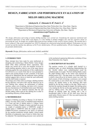
- 1. IJRET: International Journal of Research in Engineering and Technology eISSN: 2319-1163 | pISSN: 2321-7308 _______________________________________________________________________________________ Volume: 04 Issue: 07 | July-2015, Available @ http://www.ijret.org 78 DESIGN, FABRICATION AND PERFORMANCE EVALUATION OF MELON SHELLING MACHINE Adedoyin R. A1 , Olatunde O. B2 , Ponle E. A3 1 Department of Mechanical Engineering Osun State Polytechnic Iree, Osun State. Nigeria. 2 Department of Mechanical Engineering Osun State Polytechnic Iree, Osun State. Nigeria. 3 Department of Mechanical Engineering University of Ibadan, Oyo State. Nigeria. olatundeolanrewaju07@yahoo.com Abstract The design, fabrication and testing of melon shelling machine were carried out. Considering the numerous nutritional and economical importance of the melon seed (Egusi) it is only binding to fashion drudgery free and less expensive means of processing the seed. An insight was carefully taken from previous attempts on this work by various scholars. The machine has a power rating of 1.5hp, power transmitted was 1656.70 wattsand was constructed using basically mildsteel. Performance test was carried out and the machine has efficiency of 62.5% for shelled melon, 10% for unshelled melon, 10% for breakage and 17.5% for partially shelled melon. Keywords: Design, fabrication, melon seed, shelled, unshelled. --------------------------------------------------------------------***---------------------------------------------------------------------- 1. INTRODUCTION Many attempts have been made by some intellectuals in designing and constructing a Melon Sheller. Some designs failed while others performed below expectation. This design was carried out to solve the boredom involved in melon shelling operation which is one of the major factors militating against the scale production of this cropKolawole S.S (2012).It is as a result of this that we were prompted to improve the existing design of such a machine. It has been observed by Makanjuola that the traditional melon shelling method suggests that a device to bend the seed sufficiently until the shell breaks is required. The primary aim of this work is to design a shelling machine having efficiency well above 60% and the objectives are to save shelling time, enhance the performance of shelling machine, reduce cost of shelling, and above all to increase the rate of production of well shelled melon seed. With these objectives in mind, two different materials (flat bar and flexible rubber) where used for the shelling bar in order to test shelling efficiency of both materials. 2. METHODOLOGY Element of Shelling according to Sharma C.S & Purhit K (2003), was done where mean of unshelled melon thickness is 1.71mm and that of shelled melon is 1.60mm, hence clearance is 0.06mm. Weights of melon and chaff are given as; weight of unshelled melon is 0.000932N, weight of shelled melon is 0.000875N while the weight of chaff is 0.0000147N.Factors considered in the choice of materials for the machine production include rigidity, critical speed, flexibility of components, type of stress to which, they may be subjected. The manufacturing processes were carried out in the mechanical engineering fabrication workshop of Osun State Polytechnic Iree, Nigeria. 2.1 DESCRIPTION OF MACHINE The machine consists of a cylinder shaft inserted in a cylindrical pipe, on which theshelling blades(shelling flat bar/ flexible rubber) were welded/attached round the cylindrical pipe at an angle. The bent shelling blades creates the slight bending effect on the melon seed required for shelling action, Fig 1. The pipe rotate via a shaft attached to it which is been driven by an electric motor via a belt. The shaft consists of helix (Forming a continuous curve around the central point or axis) which serves as a conveyor. This conveys the shelled melon to the discharge after been shelled by the flat bars welded on the pipe. Melon seed is feed into the machine through the hopper, the shelling action is by rotating the flat bar on the pipe against the cylindrical wall by rubbing action. The melon is shelled and falls through an opening under the cylinder and a fan is incorporated under to blow off the chaff away from the seeds melon. Electric motor of 1.5kw was used to power the melon shelling machine. Fig.1. Slight Bending of the melon seed
- 2. IJRET: International Journal of Research in Engineering and Technology eISSN: 2319-1163 | pISSN: 2321-7308 _______________________________________________________________________________________ Volume: 04 Issue: 07 | July-2015, Available @ http://www.ijret.org 79 2.2 DESIGN CALCULATIONS DESIGN THEORY The various components produced and tested were: Solid shaft, hopper, shelling cylinder, pipe and flat bars, bearing, frame and bearing house. According to J.E Shirley (1989), Design for shelling pipe was given using the formula shown below Shelling pipe area Ap = πr2 (1) rp = radius of the pipe; volume of shelling pipe Vp = πr2 LP (2) Where Lp = length of the shelling pipe Area of shelling cylinder Ac = πr2 (3) Where rc = radius of shelling cylinder; volume of shelling cylinder Vc = πrc 2 Lc (4) Clearance between shelling cylinder and shelling pipe (5) Where hp = height of the flat bar on pipe. hc = height of shelling cylinder V1 = 1/3 x base area x height – volume for hopper Where Vh= volume of hopper H = height of hopper 2.2.1 DESIGNS FOR SHAFT Design for shaft involves analyzing the various forces acting on the shaft and obtaining the required diameter that will withstand the force according to M.F Spotts (1991).were by shown below give us the Algebraic sum of forces acting on the member is equal to zero. That is RA + RB = W1 + W2 + W3 (6) RB = W1 + W2 + W3 - RA 2.2.2 SHEAR FORCES ON SHAFT (S.F) Shear force on shaft is the algebraic sum of forces acting to one side of the section according to Allen S.H and Alfred R.H (1982).the diagram shown below analyzed the Shear forces at various sections that is W1 W2 W3 X1 X2 X3 Fig.2. Forces Acting on Shaft = W1- RA + W2 – RB + W3 (X1 + X2) ≤ X ≤ (X1 + X2) ≤ X ≤ (X1 + X2 + X3) Forces required to rotate the shaft according to J.E Shirley (1989), (7) Where P = power of electric motor ώ = Angular Velocity rm = Radius of Motor Shaft But (8) Where N = Speed of Motor in rev/min Torque is the work required in rotating the shaft. (9) Also T = Frs (10) Where rs is the shaft radius However, torque can also be obtained from the following relation: (11) Where T = Applied Torque J = Polar Moment of Area ι = Shear Stress G = Modulus of Rigidity φ = Angle of twist L = Length of Shaft 2.2.3 SPEED CONTROL The need to regulate or control the speed of the motor to some certain limit become necessary because too high speed will crush the melon and too low speed can over stress the shelling teeth. The formula crush the melon and too low speed can over stress the shelling teeth. The formula N1D1 = N2D2 according to Sharma C.S and Purchit Kamalesh (2003), Where N1 = Speed of Electric Motor, D1 = Diameter of Pulley on Electric Motor, N2 = Speed of Shaft, D2 = Diameter of Pulley on Shaft. 2.2.4 BELT DRIVE Belt drives uses the friction that exists between the pulley and belt to transmit a torque. The belt is stretched between the pulley with an initial tension T1, i.e. the one supply the torque to transmit the power via the friction between the contact surface of the belt and pulley. The transmitted torque is solely in the belt during operation, there being a “tight” side and a “slack” side T1 +B +A T2 Fig.3. Vee-Belt The belt selected in this design is the vee-belt. The vee belt Fig. 2, has a special tapered section of vee shape, which is located in vee grooves in the circumference of the pulley. This gives a positive location and increases the normal reaction between the contact surfaces of the belt and pulley. The belt tension ratio is given by (12)
- 3. IJRET: International Journal of Research in Engineering and Technology eISSN: 2319-1163 | pISSN: 2321-7308 _______________________________________________________________________________________ Volume: 04 Issue: 07 | July-2015, Available @ http://www.ijret.org 80 According to M.E Spotts (1988) Where θ is the angle of contact between the belt and the pulley, also known as the ship angle. µ = Coefficient of Friction α = The Pulley Grooves Angle θ1 = Ship Angle in Radian. 2.2.5 POWER TRANSMISSION BY BELT The driving pulley causes a difference in tension in the belt which is transferred to the driven pulley. The driven thus experiences a torque which is caused by the difference in tension in the belt. Since power transmission in belt involves two pulleys, then torque on driving pulley A. = (T1 – T2) rA (13) and torque on driven pulley B = (T1 – T2) rB (14) Now, power transmitted = Torque x Angular Velocity. PA = (T1 - T2) rAωA from pulley A And from pulley B PB = (T1 - T2) rBωB But and which is equal to the speed and power transmitted = (T1 – T2)r Watts …. Where rA = radius of Pulley on Electric Motor rB = radius of the Pulley on Shaft (Shelling Shaft) 2.2.6 LENGTH OF BELT (15) according to Aaron D. Deustchamn (1975), Where LB = Length of Belt D2 = Diameter of Pulley on Shaft D1 = Diameter of Pulley on Electric Motor C = Centre Distance Between Pulley. 2.2.7 BEARING This is a machine part which supports another part which rotates slides or oscillates in it, or on it.Bearing are in different categories and types and their function is to reduce friction between two rotating parts. It reduces wear and reduces heat to be generated due to friction and support load on rotating parts. For the purpose of this design a ball bearing of bore 25mm was selected. 2.8 DESIGN ANALYSIS Parameters Equations Area of pipe A = πrp 2 Volume of pipe Vp = πrp 2 Lp Area of shelling cylinder Ac = πrc 2 Volume of shelling cylinder. Vc = πrc 2 Lc Clearance between shelling pipe and shelling cylinder. Clearance between Cylinder and Pipe SHEAR FORCE ON SHAFT 0.06N/mm 0.3N/mm 0.13N/mm 40mm 200mm 40mm -25.48N 34.52N 2.4N S.F Diagram
- 4. IJRET: International Journal of Research in Engineering and Technology eISSN: 2319-1163 | pISSN: 2321-7308 _______________________________________________________________________________________ Volume: 04 Issue: 07 | July-2015, Available @ http://www.ijret.org 81 Force required to rotate Speed reduction From equation N1D1 π = N2D2 π BEARING SELECTION Pr = XR+YT Pr = equivalent radial load L10 = (C /p) k x 106 C = (2,420 x 4.448)N from the bearing load table for bearing having 25mm Bore K =3 for ball bearing L10 = ( 2,420 x 4.448 )3 818.4 = 2275 x 106 rev Capacity requirement, Cr = p ( L10N )1/3 z Cr = capacity requirement Z = constant for ball bearing from bearing table Cr = 1723589.98 2.3 TESTING OF THE MACHINE The efficiency of the melon shelling machine was determined by testing theprocessed melon seeds, wettedto increase the moisture content and thereby reduce the brittleness of the seed in order to ease the problem of seed breakage, since percentage seed breakage is found to reduce with increased moisture content of melon seed, Shittu and Ndrika (2012).Equally weighed melon seeds were fed into the machine via the hopper to test for percentage efficiency in both cases (flexible rubber and then flat bar). 3. RESULTS AND DISCUSSION Table 1 below shows percentage performance of the machine in terms of shelled, unshelled, damaged and partially shelled melon seeds when the Flexible rubber and the flat bar were used for shelling. It is observed from the tabulated result shown that a higher percentage of seed was shelled making use of the Flexible rubber, likewise a higher percentage of partially shelled seeds was obtained. However, the advantage of a higher shelled seed out-weight the disadvantage of possible higher partially shelled seeds when the Flexible rubber is used. Table 1: Calculated Percentage Efficiency Considering Shelled, Unshelled, Damaged and Partially Shelled Melon Seeds Method Percentag e seeds shelled (%) Percentag e seeds unshelled (%) Percentag e seeds damaged (%) Percentag e seeds partially shelled (%) Flexibl e rubber 70.95 6.5 4.75 17.8 Flat bar 62.5 10.0 10.0 17.5 4. CONCLUSION In this work, the melon shelling machine was designed, constructed and tested using two different materials (flat bar and flexible rubber) for shelling with 62.5% and 70.95% efficiency respectively. A need to bend the melon seed sufficiently till breakage, requires some amount of flexibility which is evident in the greater percentage seeds shelled, lesser percentage seed unshelled, and lesser percentage damaged seeds, obtained from using the flexible rubber. However, the use of flexible rubber lead to higher percentage seeds partially shelled, this disadvantage does not out weigh the above mentioned advantages observed by making use of the flexible rubber.This shows the improvement in performance of melon shelling machine as a result of the design flexibility. REFERENCES [1] Aaron D. Deustchamn (1975), Machine Design (theory and practices) CollierMacmillan Publishers. [2] Adekunle A.S (2009),Development and Performance manually & motorized melon shelling machine. [3] Allen S.H and Alfred R.H (1982), Theory and Problems of Machine Design McGrew-Hill Book co. Singapore pp. 114, 138 and [4] Kolawole S.S (2012),Development and Performance tests of a melon (Egusi) Seed [5] Orisaleye J.T, Danisa O, Ojolo S.J & Ogbonanya C. (2010). Design and Development of Cashew Nut Shelling Machine. [6] Sharma C.S and Purchit Kamalesh (2003), Design of machine elements, Prentice Hill of Indian, New Delhi. [7] Shirley J.E (1989), Mechanical Engineering Design. 5th Edition, Mc Grew-Hill Book co. pp 54, 55 and 93. [8] Shirley J.E (1989),Mechanical Engineering Design. 5th Edition, Mc Grew-Hill Book co. pp 389 - 399.
- 5. IJRET: International Journal of Research in Engineering and Technology eISSN: 2319-1163 | pISSN: 2321-7308 _______________________________________________________________________________________ Volume: 04 Issue: 07 | July-2015, Available @ http://www.ijret.org 82 [9] Spotts M.E. (1988), Design of Machine Element, 6th Edition, Prentice Hill of Indian Private Limited, New Delhi pp 149 - 157. [10]Spotts M.E. (1991),Design of Machine Element, Prentice Hill of Indian Private Limited, 6th Edition. [11]S. K. Shittu and V. I. O. Ndrika., (2012). Development and performance tests of a melon (egusi) seed shelling machine. Agric Eng: CIGR Journal, issue 14, Pp. 1