SlideShare une entreprise Scribd logo
1  sur  15
Electrical Characteristics of Bicycle Dynamos

Summary

Bicycle Dynamos are alternators equipped with permanent magnets. They are typically claw-
pole generators and deliver energy at rather low rpm.
The sidewall-running bottle dynamo used to be the most popular type for many years, but today
the hub dynamo has taken over. There are a few other types (spoke dynamo, roller dynamo) but
those gained limited popularity.
This page focuses on the electrical characteristics of a typical bicycle dynamo and the maximum
power that can be extracted from it.

Dynamo Power

In Europe, most bicycle dynamos are rated 3W (that is 500mA at 6V). For sure, the power of a
dynamo light system depends somewhat on the speed. In a standard light system, the power is
zero at standstill, at moderate speed it's 3W and at very high speed, it's just a little bit more than
3W. Some manufacturers include limiting zener diodes or other forms of overvoltage protection,
to make sure the voltage doesn't rise to levels that kill the light bulb(s).

Test Units

I've tested 3 dynamos (from left to right): Busch + Müller Dymotec6, AXA HR and a cheap one
from my local supermarket.


   1. The B&M Dymotec6 has the best mechanics. It runs very well on the side of the tire.
      This dynamo is often found on high-quality touring bikes. I paid EUR 24.90 for this (yr
      2004).
2. The AXA HR has the strongest magnets, it delivers the highest current. It contains 2
      zener diodes (BZX 85C 7V5) in series, to limit the output voltage. I had to open the glued
      plastic enclosure in order to remove these diodes for the measurements. This dynamo is
      often found on branded bikes. I paid EUR 16.99 for the AXA HR.
   3. The cheapy from the local supermarket has a magnetic performance slightly inferiour to
      the Dymotec6. The mechanics are not designed for heavy use but it received all required
      approvals. It's held together by two screws and can be completely disassembled. This
      dynamo is usually stock on supermarket bikes. Riders who rarely ride in the dark may
      like this unit at a bargain price of just EUR 3.45

Tools

For measuring the electrical characteristics of bicycle dynamos, I've created this instrument. It
measures the speed of a bike based on the rpm of the dynamo:
                                                           This equiment is built from a
                                                           Panasonic flashlight and a Trelock FC
                                                           404 bicycle computer. It includes
                                                           additional circuitry (see below) to slice
                                                           the AC voltage from the dynamo and
                                                           divide it to a lower frequency that the
                                                           bicycle computer can handle.

                                                           Initially, I designed this with a cheap
                                                           no-name bicycle computer. I soon
                                                           found that this does some terrible
                                                           rounding at higher speeds. I switched
                                                           to a branded item, the Trelock FC 404.
                                                           It displays the decimals of the speed
                                                           and it does so correctly.

                                                           To properly set the wheel
                                                           circumference in the bicycle computer,
                                                           it's necessary to know the diameter of
                                                           the dynamo wheel as well as the
                                                           number of magnet poles. Most sidewall
                                                           dynamos have 8 poles - you can feel 8
                                                           steps per rotation of the wheel (and
                                                           measure 4 full sine waves per rotation).
                                                           Refer to the formula below.
Other tools used for the measurements below are multimeters, oscilloscope, a lab power supply
and an adjustable current sink based on the LM317T linear regulator IC.

Measurements

Maximum Power of different Dynamos

Setup: Dynamo, voltage doubler (Greinacher type using 2x 1N5818 & 2x 1000uF), current sink
(variable from 100 to 250 mA). Speedmeter connected to dynamo.
Procedure: Run the dynamo at 15 km/h. Measure the voltage across the current sink for currents
100, 130, 160, 190, 220, 250 mA. Repeat at 40 km/h. Do this for each of the 3 dynamos.
Calculate power from voltage and current. Plot power vs load current.
Observation: AXA HR delivers maximum power at 200 mA load current (note this is after
voltage doubling !), B&M Dymotec6 at 180 mA, the cheapy at 160 mA. The absolute power
levels show the AXA HR on top and the cheapy on the bottom at any speed. Conclusion: The
maximum power is achieved at a specific load current. This depends little on the speed, but
mostly on the dynamo. In other words: A dynamo is a current source.

Power vs Speed of Dymotec6

I chose to do this measurement with the Busch & Müller Dymotec6. The nature of the curve is
similar for other dynamos, only they would meet a slightly higher or lower power.

Setup: Dymotec6, voltage doubler (Greinacher type using 2x 1N5818 & 2x 1000uF), 180 mA
current sink. Speedmeter connected to dynamo.
Procedure: Run the dynamo at 4, 5, 7, 9, 12, 15, 19, 24, 31, 40, 50 km/h and measure the voltage
across the current sink. Plot for each speed the calculated power = measured voltage * 180 mA
current.
Conclusion: With perfect matching of the load, Dymotec6 delivers 2.7 W at moderate speed, 5
W at high speed and 6 W at really high speed. This is what can be achieved without modification
to the dynamo.
Question: Why does a standard 3 W light system with the Dymotec6 not burn out the bulbs at 50
km/h ? This is because at such high speed, the matching of the load is off (current is too high) so
that it can't drain maximum power.
Question: Where goes the lost energy when the load doesn't drain the maximum possible power ?
It's not lost. The dynamo spins with less effort. Try and short-circuit the dynamo at full speed,
the current of the driving motor will drop a lot.

Temperature Performance of Dymotec6

As the dynamo runs for extended periods of time, its temperature increases. This test runs the
B+M Dymotec6 at 50 km/h and 23ºC ambient temperature. The Greinacher doubler circuit (2x
1N5818 & 2x 1000uF) and a 180 mA load is connected. The power into the load is being
monitored. The experiment is stationary on the workbensch, so there's no draught to cool the
dynamo. After around 20 minutes, the dynamo output power has decreased from an inital 100%
to 80%. For another 10 minutes, it doesn't drop any further. The temperature on the casing of the
dynamo measures 89ºC at the end of these 30 minutes. It's considerably hotter inside.


Continuing this experiment, a standard 80mm computer fan is mounted to provide some cooling
as it would be on a moving bike. The power increases and eventually stabilizes at 89% of the
start value. The temperature stabilizes at around 40ºC.

The Dymotec6 was chosen for this experiment as it has the best mechanical design of all tested
dynamos. It doesn't suffer any noticable deterioration after running at 50 km/h and delivering
well above 5 W for 2 hours. A lot of dynamos don't withstand this. Bearings and their lubrication
suffer from the high internal temperature, resulting in rapid wear. Once the rotating magnet
comes into contact with the stator, friction and internal temperature dramatically increase, the
dynamo body melts and eventually the rotor jams. In my setup, this just tears the coupling
between motor and dynamo while on a real bike, the dynamo wheel may pop off so that the rotor
shaft causes damage to tire, rim or spokes. Bottom line: Avoid using a cheap dynamo to assist
the brakes on long descents.

                 Horsepower Design Equations and Formulas Calculator
                                  Automobile - Car - Truck


                                       Solving for torque.
This calculation corrects horsepower for normally aspirated internal combustion engine to a
        standard humidity, pressure and temperature after mesaured on a dynamometer.


Voltage-
E=pi*z*N*P/60*A
here pi=magnetic field density/area of magnetic field
z=no of conductors
N=speed in rpm
A=no of parallel path(=2 for wave &=P for lap windings)
P=no of poles

Power-
P=tau*2*Pi*omega

where tau=torque
and omega=rotational speed rads^-1


In case of dynamos ,the output is generally in terms of power.If you calculate output power then
you can know the energy by multiplying it with time.

   Calculation of power:

    In ideal conditions i.e no losses, Output electrical energy=Input mechanical energy.But we
must consider the losses that occur in a dynamo(or generator).The losses that occur are iron or
core losses and copper losses.Iron losses are of two types


1)Hysteresis losses(in watts)=khBfv


2)Eddy current losses(in watts)=keB2f2t2

kh=hysteresis constant

ke=eddy current constant
B=magnetic flux density

f=frequency

t=thickness

v=volume
Copper losses:Ise2R+Ish2R(Series field copper losses+shunt field copper losses)


Apart from these losses there are armature losses and mechanical losses.

Armature losses:Ia2R


Basically we calculate output power by subtracting the losses from the input power.
             Input power=output power+losses
=>           Output power=input power-losses
=>Output power=input power - Ia2Ra - Ise2R - Ish2R
                   - mechanical losses-other losses
But for converting mechanical to electrical energy without using field winding,then the equation
will be:
             Output power=input power - Ia2Ra - mechanical losses
                            - other losses
Calculate the output power and multiply it with time(considering power independent of time) to
get the energy produced.

Ia can be calculated from the following equation

           E=IaRa + VL + BCD           (BCD=brush contact drop negligible)

           VL=load voltage

       Ra=armature resistance

           E=emf produced=oNZP/60A

           o = flux due to rotation
           N=speed in r.p.m
           Z=number of armature conductors
           P=number of poles
           A=number of parallel paths
Solving for force


How to calculate how much watts and voltage a crude dynamo will generate?
I want to calculate amount of electricity generated by an AC dynamo, given the width and
length or copper wire used as coil and size and power of the magnet.


AC is generated by generators, not dynamos; a dynamo is a DC generator. Second problem: it
depends on the speed of rotation of the rotor, among other things. Now to some basic physics:
a standard commercial AC generator consists of a rotor, carrying a constant magnetic field; the
field may arise from permanent magnets or from an electromagnet, powered by a separate DC
generator (called an exciter). The fixed part of the machine has copper windings, in which
voltage is induced by the turning of the rotor. The voltage is proportional to the speed of
rotation, the strength of the magnetic field, the number of turns of wire, and the area of the
loops through which the magnetic field passes. The available current depends on the size of the
wire, but is also limited by the torque available to turn the rotor. Some typical values: the
magnetic field of the rotor is usually on the order of 0.3 Tesla or so. For AC use for commercial
power generation, 3600 rpm is the usual speed. For 20 amperes out, 12 gauge wire can be used
if you have forced-air cooling. Typical output voltages for commercial use range from 4160 to
13,200 or more. The fundamental relationship: a one-turn coil of one square meter, through
which passes a magnetic field changing at the rate of one Tesla per second, will show an open-
circuit voltage of one volt.


Handy Formula to calculate the output of any generator at any given RPM…….

First off 3 thing must be known… RPM, Open voltage at that RPM and the Ohm's
of the stator coil.

                  1. Measure the RPM
                  2. Measure the Open voltage at that RPM
3. Measure the Ohm's of the stator coil.

Measured RPM / Open volts = RPM per volt

To find a Desired output the formula is:

Volts + ( Amps * Ohms ) = Open Voltage ( necessary to achieve this output )

Open voltage * RPM per volt = RPM needed to achieve desired output


Example: Alternator spinning at 1500 RPM delivers an open voltage of 34.8 volts
so….

1500 / 34.8 = 43.1 RPM per volt

The stator coil reading is .6 ohm


Lets say we would like 14.6 volts at 10 amps from our unit

14.6 volts + ( 10 amps * .6 ohm ) =20.6 open voltage

20.6 * 43 rpm per volt = 885.8 RPM

If you would like to know an output at a certain RPM you simply change the
formula to:

RPM / RPM per volt =Open Voltage

(OpenVoltage-desiredvoltage) /ohms = Amps

Example: 885 RPM at 14.6 volts

885 / 43 = 20.58

( 20.58 - 14.6 ) / .6 = 9.97 amps


And there you have it… since, for the most part, the voltage and rpm are a
constant its easy to calculate the output of any unit

Dynamo
Main article: Dynamo


Dynamos are no longer used for power generation due to the size and complexity of the
commutator needed for high power applications. This large belt-driven high-current dynamo
produced 310 amperes at 7 volts, or 2,170 watts, when spinning at 1400 RPM.


Dynamo Electric Machine [End View, Partly Section] (U.S. Patent 284,110)

The dynamo was the first electrical generator capable of delivering power for industry. The
dynamo uses electromagnetic induction to convert mechanical rotation into direct current
through the use of a commutator. The first dynamo was built by Hippolyte Pixii in 1832.

Through a series of accidental discoveries, the dynamo became the source of many later
inventions, including the DC electric motor, the AC alternator, the AC synchronous motor, and
the rotary converter.

A dynamo machine consists of a stationary structure, which provides a constant magnetic field,
and a set of rotating windings which turn within that field. On small machines the constant
magnetic field may be provided by one or more permanent magnets; larger machines have the
constant magnetic field provided by one or more electromagnets, which are usually called field
coils.
Large power generation dynamos are now rarely seen due to the now nearly universal use of
alternating current for power distribution and solid state electronic AC to DC power conversion.
But before the principles of AC were discovered, very large direct-current dynamos were the
only means of power generation and distribution. Now power generation dynamos are mostly a
curiosity.

[edit] Alternator

Without a commutator, a dynamo becomes an alternator, which is a synchronous singly fed
generator. Alternators produce alternating current with a frequency that is based on the rotational
speed of the rotor and the number of magnetic poles.

Automotive alternators produce a varying frequency that changes with engine speed, which is
then converted by a rectifier to DC. By comparison, alternators used to feed an electric power
grid are generally operated at a speed very close to a specific frequency, for the benefit of AC
devices that regulate their speed and performance based on grid frequency. Some devices such as
incandescent lamps and ballast-operated fluorescent lamps do not require a constant frequency,
but synchronous motors such as in electric wall clocks do require a constant grid frequency.

When attached to a larger electric grid with other alternators, an alternator will dynamically
interact with the frequency already present on the grid, and operate at a speed that matches the
grid frequency. If no driving power is applied, the alternator will continue to spin at a constant
speed anyway, driven as a synchronous motor by the grid frequency. It is usually necessary for
an alternator to be accelerated up to the correct speed and phase alignment before connecting to
the grid, as any mismatch in frequency will cause the alternator to act as a synchronous motor,
and suddenly leap to the correct phase alignment as it absorbs a large inrush current from the
grid, which may damage the rotor and other equipment.

Typical alternators use a rotating field winding excited with direct current, and a stationary
(stator) winding that produces alternating current. Since the rotor field only requires a tiny
fraction of the power generated by the machine, the brushes for the field contact can be relatively
small. In the case of a brushless exciter, no brushes are used at all and the rotor shaft carries
rectifiers to excite the main field winding.

Vehicle-mounted generators

Early motor vehicles until about the 1960s tended to use DC generators with electromechanical
regulators. These have now been replaced by alternators with built-in rectifier circuits, which are
less costly and lighter for equivalent output. Moreover, the power output of a DC generator is
proportional to rotational speed, whereas the power output of an alternator is independent of
rotational speed. As a result, the charging output of an alternator at engine idle speed can be
much greater than that of a DC generator. Automotive alternators power the electrical systems on
the vehicle and recharge the battery after starting. Rated output will typically be in the range 50-
100 A at 12 V, depending on the designed electrical load within the vehicle. Some cars now have
electrically powered steering assistance and air conditioning, which places a high load on the
electrical system. Large commercial vehicles are more likely to use 24 V to give sufficient power
at the starter motor to turn over a large diesel engine. Vehicle alternators do not use permanent
magnets and are typically only 50-60% efficient over a wide speed range.[4] Motorcycle
alternators often use permanent magnet stators made with rare earth magnets, since they can be
made smaller and lighter than other types. See also hybrid vehicle.

A magneto, like a dynamo, uses permanent magnets but generates alternating current like an
alternator. Because of the limited field strength of permanent magnets, magnetos are not used for
high-power production applications, but are very reliable. This reliability is part of why they are
used in aviation piston engines.

Some of the smallest generators commonly found power bicycle lights. Called a bottle dynamo
these tend to be 0.5 ampere, permanent-magnet alternators supplying 3-6 W at 6 V or 12 V.
Being powered by the rider, efficiency is at a premium, so these may incorporate rare-earth
magnets and are designed and manufactured with great precision. Nevertheless, the maximum
efficiency is only around 80% for the best of these generators—60% is more typical—due in part
to the rolling friction at the tire–generator interface from poor alignment, the small size of the
generator, bearing losses and cheap design. The use of permanent magnets means that efficiency
falls even further at high speeds because the magnetic field strength cannot be controlled in any
way. Hub dynamos remedy many of these flaws since they are internal to the bicycle hub and do
not require an interface between the generator and tire. Until recently, these generators have been
expensive and hard to find. Major bicycle component manufacturers like Shimano and SRAM
have only just[when?] entered this market. However, significant gains can be expected in future as
cycling becomes more mainstream transportation and LED technology allows brighter lighting at
the reduced current these generators are capable of providing.

Sailing yachts may use a water or wind powered generator to trickle-charge the batteries. A small
propeller, wind turbine or impeller is connected to a low-power alternator and rectifier to supply
currents of up to 12 A at typical cruising speeds.

Still smaller generators are used in micropower applications.

[edit] Engine-generator

Main article: Engine-generator


The Caterpillar 3512C Genset is an example of the engine-generator package. This unit produces
1225 kilowatts of electric power.
An engine-generator is the combination of an electrical generator and an engine (prime mover)
mounted together to form a single piece of self-contained equipment. The engines used are
usually piston engines, but gas turbines can also be used. And there are even hybrid diesel-gas
units, called dual-fuel units. Many different versions of engine-generators are available - ranging
from very small portable petrol powered sets to large turbine installations. The primary
advantage of engine-generators is the ability to independently supply electricity, allowing the
units to serve as backup power solutions.[5]

State the laws of electromagnetic induction.

Ans. Laws of electromagnetic induction:
(i) A current carrying conductor placed in a magnetic field experiences a
force.
(ii) The amount of e.m.f. produced is directly proportional to rate of change
of flux.


Explain the principle and working of a D.C. generator?

Ans. D.C. generator converts mechanical energy to electrical energy. It
works on principle of electromagnetic induction. Whenever a current carrying
conductor is placed in a magnetic field it experiences a force. In D.C.
generator e.m.f. is induced dynamically i.e. flux linkage with the conductor
change due to movment of conductor. The vvorking of a single coil simple
D.C. generator is explained below:
A simple D.C. generator consists of a magnetic field set up by permanent
magnet and a conductor is placed in this field. The conductor is made to
move in the magnetic field so that it cuts magnetic lines of force and an
e.m.f. is induced . The direction of induced e.m.f. is given by Fleming’s right
hand rule.
The e.m.f. so induced produces a current in coil which is collected through
split rings and commulator.

Contenu connexe

En vedette

Efficient Motor Control Solutions: High Performance Servo Control (Design Con...
Efficient Motor Control Solutions: High Performance Servo Control (Design Con...Efficient Motor Control Solutions: High Performance Servo Control (Design Con...
Efficient Motor Control Solutions: High Performance Servo Control (Design Con...Analog Devices, Inc.
 
Alternating Current Machines 1a
Alternating Current Machines 1aAlternating Current Machines 1a
Alternating Current Machines 1aTalia Carbis
 
Assignment & solution (selected)
Assignment & solution (selected)Assignment & solution (selected)
Assignment & solution (selected)efrataderebe
 
Chapter 3 induction machine
Chapter 3 induction machineChapter 3 induction machine
Chapter 3 induction machinemkazree
 
12th CBSE Physics Project AC Generator
12th CBSE Physics Project AC Generator12th CBSE Physics Project AC Generator
12th CBSE Physics Project AC GeneratorAshwin Francis
 
Numerical examples
Numerical examplesNumerical examples
Numerical examplesFelipe Gomes
 

En vedette (8)

Project Report
Project ReportProject Report
Project Report
 
Efficient Motor Control Solutions: High Performance Servo Control (Design Con...
Efficient Motor Control Solutions: High Performance Servo Control (Design Con...Efficient Motor Control Solutions: High Performance Servo Control (Design Con...
Efficient Motor Control Solutions: High Performance Servo Control (Design Con...
 
Alternating Current Machines 1a
Alternating Current Machines 1aAlternating Current Machines 1a
Alternating Current Machines 1a
 
Assignment & solution (selected)
Assignment & solution (selected)Assignment & solution (selected)
Assignment & solution (selected)
 
Chapter 3 induction machine
Chapter 3 induction machineChapter 3 induction machine
Chapter 3 induction machine
 
12th CBSE Physics Project AC Generator
12th CBSE Physics Project AC Generator12th CBSE Physics Project AC Generator
12th CBSE Physics Project AC Generator
 
A.C GENERATOR
A.C GENERATORA.C GENERATOR
A.C GENERATOR
 
Numerical examples
Numerical examplesNumerical examples
Numerical examples
 

Similaire à Electrical Characteristics of Bicycle Dynamos

Presentation on Power Saving from Two – Wheeler Bike Silencer
Presentation on Power Saving from Two – Wheeler Bike SilencerPresentation on Power Saving from Two – Wheeler Bike Silencer
Presentation on Power Saving from Two – Wheeler Bike SilencerMd Anzar Aman
 
Motor Selection.pptx
Motor Selection.pptxMotor Selection.pptx
Motor Selection.pptxAsad Khan
 
Torque Measurement Primer
Torque Measurement PrimerTorque Measurement Primer
Torque Measurement PrimerInterface
 
POWER FACTOR CORRECTION OF A 3-PHASE 4- SWITCH INVERTER FED BLDC MOTOR
POWER FACTOR CORRECTION OF A 3-PHASE 4- SWITCH INVERTER FED BLDC MOTORPOWER FACTOR CORRECTION OF A 3-PHASE 4- SWITCH INVERTER FED BLDC MOTOR
POWER FACTOR CORRECTION OF A 3-PHASE 4- SWITCH INVERTER FED BLDC MOTORvanmukil
 
Understanding Electric Motors
Understanding Electric MotorsUnderstanding Electric Motors
Understanding Electric Motorsiratepaddle343
 
Special motors
Special motorsSpecial motors
Special motorsmadhu1729
 
power generation through speed breakers
power generation through speed breakerspower generation through speed breakers
power generation through speed breakersMonisha Singh
 
1694355611974.pdf
1694355611974.pdf1694355611974.pdf
1694355611974.pdfNafir Anas
 
Understanding Electric Motors
Understanding Electric MotorsUnderstanding Electric Motors
Understanding Electric Motorsabusivelexicon144
 
Akribis atr(en) 040712 brochure
Akribis atr(en) 040712 brochureAkribis atr(en) 040712 brochure
Akribis atr(en) 040712 brochureElectromate
 
More About Stepper Motors
More About Stepper MotorsMore About Stepper Motors
More About Stepper Motorsiratepaddle343
 
Kollmorgen 6410 6415_stepper_drive_catalog
Kollmorgen 6410 6415_stepper_drive_catalogKollmorgen 6410 6415_stepper_drive_catalog
Kollmorgen 6410 6415_stepper_drive_catalogElectromate
 

Similaire à Electrical Characteristics of Bicycle Dynamos (20)

Matematica motor cc
Matematica motor  ccMatematica motor  cc
Matematica motor cc
 
Man Sew
Man SewMan Sew
Man Sew
 
Automatons
AutomatonsAutomatons
Automatons
 
Thor power, technical summary, 1210
Thor power, technical summary, 1210Thor power, technical summary, 1210
Thor power, technical summary, 1210
 
Presentation on Power Saving from Two – Wheeler Bike Silencer
Presentation on Power Saving from Two – Wheeler Bike SilencerPresentation on Power Saving from Two – Wheeler Bike Silencer
Presentation on Power Saving from Two – Wheeler Bike Silencer
 
Motor Selection.pptx
Motor Selection.pptxMotor Selection.pptx
Motor Selection.pptx
 
Torque Measurement Primer
Torque Measurement PrimerTorque Measurement Primer
Torque Measurement Primer
 
POWER FACTOR CORRECTION OF A 3-PHASE 4- SWITCH INVERTER FED BLDC MOTOR
POWER FACTOR CORRECTION OF A 3-PHASE 4- SWITCH INVERTER FED BLDC MOTORPOWER FACTOR CORRECTION OF A 3-PHASE 4- SWITCH INVERTER FED BLDC MOTOR
POWER FACTOR CORRECTION OF A 3-PHASE 4- SWITCH INVERTER FED BLDC MOTOR
 
dynamic braking resistor selection calculation
dynamic braking resistor selection calculationdynamic braking resistor selection calculation
dynamic braking resistor selection calculation
 
Understanding Electric Motors
Understanding Electric MotorsUnderstanding Electric Motors
Understanding Electric Motors
 
Special motors
Special motorsSpecial motors
Special motors
 
Experiment 2 AC Machines
Experiment 2 AC MachinesExperiment 2 AC Machines
Experiment 2 AC Machines
 
More About Stepper Motors
More About Stepper MotorsMore About Stepper Motors
More About Stepper Motors
 
ELEKTRA_new
ELEKTRA_newELEKTRA_new
ELEKTRA_new
 
power generation through speed breakers
power generation through speed breakerspower generation through speed breakers
power generation through speed breakers
 
1694355611974.pdf
1694355611974.pdf1694355611974.pdf
1694355611974.pdf
 
Understanding Electric Motors
Understanding Electric MotorsUnderstanding Electric Motors
Understanding Electric Motors
 
Akribis atr(en) 040712 brochure
Akribis atr(en) 040712 brochureAkribis atr(en) 040712 brochure
Akribis atr(en) 040712 brochure
 
More About Stepper Motors
More About Stepper MotorsMore About Stepper Motors
More About Stepper Motors
 
Kollmorgen 6410 6415_stepper_drive_catalog
Kollmorgen 6410 6415_stepper_drive_catalogKollmorgen 6410 6415_stepper_drive_catalog
Kollmorgen 6410 6415_stepper_drive_catalog
 

Electrical Characteristics of Bicycle Dynamos

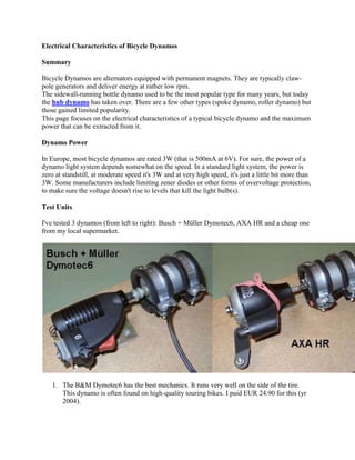
  • 1. Electrical Characteristics of Bicycle Dynamos Summary Bicycle Dynamos are alternators equipped with permanent magnets. They are typically claw- pole generators and deliver energy at rather low rpm. The sidewall-running bottle dynamo used to be the most popular type for many years, but today the hub dynamo has taken over. There are a few other types (spoke dynamo, roller dynamo) but those gained limited popularity. This page focuses on the electrical characteristics of a typical bicycle dynamo and the maximum power that can be extracted from it. Dynamo Power In Europe, most bicycle dynamos are rated 3W (that is 500mA at 6V). For sure, the power of a dynamo light system depends somewhat on the speed. In a standard light system, the power is zero at standstill, at moderate speed it's 3W and at very high speed, it's just a little bit more than 3W. Some manufacturers include limiting zener diodes or other forms of overvoltage protection, to make sure the voltage doesn't rise to levels that kill the light bulb(s). Test Units I've tested 3 dynamos (from left to right): Busch + Müller Dymotec6, AXA HR and a cheap one from my local supermarket. 1. The B&M Dymotec6 has the best mechanics. It runs very well on the side of the tire. This dynamo is often found on high-quality touring bikes. I paid EUR 24.90 for this (yr 2004).
  • 2. 2. The AXA HR has the strongest magnets, it delivers the highest current. It contains 2 zener diodes (BZX 85C 7V5) in series, to limit the output voltage. I had to open the glued plastic enclosure in order to remove these diodes for the measurements. This dynamo is often found on branded bikes. I paid EUR 16.99 for the AXA HR. 3. The cheapy from the local supermarket has a magnetic performance slightly inferiour to the Dymotec6. The mechanics are not designed for heavy use but it received all required approvals. It's held together by two screws and can be completely disassembled. This dynamo is usually stock on supermarket bikes. Riders who rarely ride in the dark may like this unit at a bargain price of just EUR 3.45 Tools For measuring the electrical characteristics of bicycle dynamos, I've created this instrument. It measures the speed of a bike based on the rpm of the dynamo: This equiment is built from a Panasonic flashlight and a Trelock FC 404 bicycle computer. It includes additional circuitry (see below) to slice the AC voltage from the dynamo and divide it to a lower frequency that the bicycle computer can handle. Initially, I designed this with a cheap no-name bicycle computer. I soon found that this does some terrible rounding at higher speeds. I switched to a branded item, the Trelock FC 404. It displays the decimals of the speed and it does so correctly. To properly set the wheel circumference in the bicycle computer, it's necessary to know the diameter of the dynamo wheel as well as the number of magnet poles. Most sidewall dynamos have 8 poles - you can feel 8 steps per rotation of the wheel (and measure 4 full sine waves per rotation). Refer to the formula below.
  • 3. Other tools used for the measurements below are multimeters, oscilloscope, a lab power supply and an adjustable current sink based on the LM317T linear regulator IC. Measurements Maximum Power of different Dynamos Setup: Dynamo, voltage doubler (Greinacher type using 2x 1N5818 & 2x 1000uF), current sink (variable from 100 to 250 mA). Speedmeter connected to dynamo. Procedure: Run the dynamo at 15 km/h. Measure the voltage across the current sink for currents 100, 130, 160, 190, 220, 250 mA. Repeat at 40 km/h. Do this for each of the 3 dynamos. Calculate power from voltage and current. Plot power vs load current.
  • 4. Observation: AXA HR delivers maximum power at 200 mA load current (note this is after voltage doubling !), B&M Dymotec6 at 180 mA, the cheapy at 160 mA. The absolute power levels show the AXA HR on top and the cheapy on the bottom at any speed. Conclusion: The maximum power is achieved at a specific load current. This depends little on the speed, but mostly on the dynamo. In other words: A dynamo is a current source. Power vs Speed of Dymotec6 I chose to do this measurement with the Busch & Müller Dymotec6. The nature of the curve is similar for other dynamos, only they would meet a slightly higher or lower power. Setup: Dymotec6, voltage doubler (Greinacher type using 2x 1N5818 & 2x 1000uF), 180 mA current sink. Speedmeter connected to dynamo. Procedure: Run the dynamo at 4, 5, 7, 9, 12, 15, 19, 24, 31, 40, 50 km/h and measure the voltage across the current sink. Plot for each speed the calculated power = measured voltage * 180 mA current.
  • 5. Conclusion: With perfect matching of the load, Dymotec6 delivers 2.7 W at moderate speed, 5 W at high speed and 6 W at really high speed. This is what can be achieved without modification to the dynamo. Question: Why does a standard 3 W light system with the Dymotec6 not burn out the bulbs at 50 km/h ? This is because at such high speed, the matching of the load is off (current is too high) so that it can't drain maximum power. Question: Where goes the lost energy when the load doesn't drain the maximum possible power ? It's not lost. The dynamo spins with less effort. Try and short-circuit the dynamo at full speed, the current of the driving motor will drop a lot. Temperature Performance of Dymotec6 As the dynamo runs for extended periods of time, its temperature increases. This test runs the B+M Dymotec6 at 50 km/h and 23ºC ambient temperature. The Greinacher doubler circuit (2x 1N5818 & 2x 1000uF) and a 180 mA load is connected. The power into the load is being monitored. The experiment is stationary on the workbensch, so there's no draught to cool the dynamo. After around 20 minutes, the dynamo output power has decreased from an inital 100% to 80%. For another 10 minutes, it doesn't drop any further. The temperature on the casing of the
  • 6. dynamo measures 89ºC at the end of these 30 minutes. It's considerably hotter inside. Continuing this experiment, a standard 80mm computer fan is mounted to provide some cooling as it would be on a moving bike. The power increases and eventually stabilizes at 89% of the start value. The temperature stabilizes at around 40ºC. The Dymotec6 was chosen for this experiment as it has the best mechanical design of all tested dynamos. It doesn't suffer any noticable deterioration after running at 50 km/h and delivering well above 5 W for 2 hours. A lot of dynamos don't withstand this. Bearings and their lubrication suffer from the high internal temperature, resulting in rapid wear. Once the rotating magnet comes into contact with the stator, friction and internal temperature dramatically increase, the dynamo body melts and eventually the rotor jams. In my setup, this just tears the coupling between motor and dynamo while on a real bike, the dynamo wheel may pop off so that the rotor shaft causes damage to tire, rim or spokes. Bottom line: Avoid using a cheap dynamo to assist the brakes on long descents. Horsepower Design Equations and Formulas Calculator Automobile - Car - Truck Solving for torque.
  • 7. This calculation corrects horsepower for normally aspirated internal combustion engine to a standard humidity, pressure and temperature after mesaured on a dynamometer. Voltage- E=pi*z*N*P/60*A here pi=magnetic field density/area of magnetic field z=no of conductors N=speed in rpm A=no of parallel path(=2 for wave &=P for lap windings) P=no of poles Power- P=tau*2*Pi*omega where tau=torque and omega=rotational speed rads^-1 In case of dynamos ,the output is generally in terms of power.If you calculate output power then you can know the energy by multiplying it with time. Calculation of power: In ideal conditions i.e no losses, Output electrical energy=Input mechanical energy.But we must consider the losses that occur in a dynamo(or generator).The losses that occur are iron or core losses and copper losses.Iron losses are of two types 1)Hysteresis losses(in watts)=khBfv 2)Eddy current losses(in watts)=keB2f2t2 kh=hysteresis constant ke=eddy current constant
  • 8. B=magnetic flux density f=frequency t=thickness v=volume Copper losses:Ise2R+Ish2R(Series field copper losses+shunt field copper losses) Apart from these losses there are armature losses and mechanical losses. Armature losses:Ia2R Basically we calculate output power by subtracting the losses from the input power. Input power=output power+losses => Output power=input power-losses =>Output power=input power - Ia2Ra - Ise2R - Ish2R - mechanical losses-other losses But for converting mechanical to electrical energy without using field winding,then the equation will be: Output power=input power - Ia2Ra - mechanical losses - other losses Calculate the output power and multiply it with time(considering power independent of time) to get the energy produced. Ia can be calculated from the following equation E=IaRa + VL + BCD (BCD=brush contact drop negligible) VL=load voltage Ra=armature resistance E=emf produced=oNZP/60A o = flux due to rotation N=speed in r.p.m Z=number of armature conductors P=number of poles A=number of parallel paths
  • 9. Solving for force How to calculate how much watts and voltage a crude dynamo will generate? I want to calculate amount of electricity generated by an AC dynamo, given the width and length or copper wire used as coil and size and power of the magnet. AC is generated by generators, not dynamos; a dynamo is a DC generator. Second problem: it depends on the speed of rotation of the rotor, among other things. Now to some basic physics: a standard commercial AC generator consists of a rotor, carrying a constant magnetic field; the field may arise from permanent magnets or from an electromagnet, powered by a separate DC generator (called an exciter). The fixed part of the machine has copper windings, in which voltage is induced by the turning of the rotor. The voltage is proportional to the speed of rotation, the strength of the magnetic field, the number of turns of wire, and the area of the loops through which the magnetic field passes. The available current depends on the size of the wire, but is also limited by the torque available to turn the rotor. Some typical values: the magnetic field of the rotor is usually on the order of 0.3 Tesla or so. For AC use for commercial power generation, 3600 rpm is the usual speed. For 20 amperes out, 12 gauge wire can be used if you have forced-air cooling. Typical output voltages for commercial use range from 4160 to 13,200 or more. The fundamental relationship: a one-turn coil of one square meter, through which passes a magnetic field changing at the rate of one Tesla per second, will show an open- circuit voltage of one volt. Handy Formula to calculate the output of any generator at any given RPM……. First off 3 thing must be known… RPM, Open voltage at that RPM and the Ohm's of the stator coil. 1. Measure the RPM 2. Measure the Open voltage at that RPM
  • 10. 3. Measure the Ohm's of the stator coil. Measured RPM / Open volts = RPM per volt To find a Desired output the formula is: Volts + ( Amps * Ohms ) = Open Voltage ( necessary to achieve this output ) Open voltage * RPM per volt = RPM needed to achieve desired output Example: Alternator spinning at 1500 RPM delivers an open voltage of 34.8 volts so…. 1500 / 34.8 = 43.1 RPM per volt The stator coil reading is .6 ohm Lets say we would like 14.6 volts at 10 amps from our unit 14.6 volts + ( 10 amps * .6 ohm ) =20.6 open voltage 20.6 * 43 rpm per volt = 885.8 RPM If you would like to know an output at a certain RPM you simply change the formula to: RPM / RPM per volt =Open Voltage (OpenVoltage-desiredvoltage) /ohms = Amps Example: 885 RPM at 14.6 volts 885 / 43 = 20.58 ( 20.58 - 14.6 ) / .6 = 9.97 amps And there you have it… since, for the most part, the voltage and rpm are a constant its easy to calculate the output of any unit Dynamo
  • 11. Main article: Dynamo Dynamos are no longer used for power generation due to the size and complexity of the commutator needed for high power applications. This large belt-driven high-current dynamo produced 310 amperes at 7 volts, or 2,170 watts, when spinning at 1400 RPM. Dynamo Electric Machine [End View, Partly Section] (U.S. Patent 284,110) The dynamo was the first electrical generator capable of delivering power for industry. The dynamo uses electromagnetic induction to convert mechanical rotation into direct current through the use of a commutator. The first dynamo was built by Hippolyte Pixii in 1832. Through a series of accidental discoveries, the dynamo became the source of many later inventions, including the DC electric motor, the AC alternator, the AC synchronous motor, and the rotary converter. A dynamo machine consists of a stationary structure, which provides a constant magnetic field, and a set of rotating windings which turn within that field. On small machines the constant magnetic field may be provided by one or more permanent magnets; larger machines have the constant magnetic field provided by one or more electromagnets, which are usually called field coils.
  • 12. Large power generation dynamos are now rarely seen due to the now nearly universal use of alternating current for power distribution and solid state electronic AC to DC power conversion. But before the principles of AC were discovered, very large direct-current dynamos were the only means of power generation and distribution. Now power generation dynamos are mostly a curiosity. [edit] Alternator Without a commutator, a dynamo becomes an alternator, which is a synchronous singly fed generator. Alternators produce alternating current with a frequency that is based on the rotational speed of the rotor and the number of magnetic poles. Automotive alternators produce a varying frequency that changes with engine speed, which is then converted by a rectifier to DC. By comparison, alternators used to feed an electric power grid are generally operated at a speed very close to a specific frequency, for the benefit of AC devices that regulate their speed and performance based on grid frequency. Some devices such as incandescent lamps and ballast-operated fluorescent lamps do not require a constant frequency, but synchronous motors such as in electric wall clocks do require a constant grid frequency. When attached to a larger electric grid with other alternators, an alternator will dynamically interact with the frequency already present on the grid, and operate at a speed that matches the grid frequency. If no driving power is applied, the alternator will continue to spin at a constant speed anyway, driven as a synchronous motor by the grid frequency. It is usually necessary for an alternator to be accelerated up to the correct speed and phase alignment before connecting to the grid, as any mismatch in frequency will cause the alternator to act as a synchronous motor, and suddenly leap to the correct phase alignment as it absorbs a large inrush current from the grid, which may damage the rotor and other equipment. Typical alternators use a rotating field winding excited with direct current, and a stationary (stator) winding that produces alternating current. Since the rotor field only requires a tiny fraction of the power generated by the machine, the brushes for the field contact can be relatively small. In the case of a brushless exciter, no brushes are used at all and the rotor shaft carries rectifiers to excite the main field winding. Vehicle-mounted generators Early motor vehicles until about the 1960s tended to use DC generators with electromechanical regulators. These have now been replaced by alternators with built-in rectifier circuits, which are less costly and lighter for equivalent output. Moreover, the power output of a DC generator is proportional to rotational speed, whereas the power output of an alternator is independent of rotational speed. As a result, the charging output of an alternator at engine idle speed can be much greater than that of a DC generator. Automotive alternators power the electrical systems on the vehicle and recharge the battery after starting. Rated output will typically be in the range 50- 100 A at 12 V, depending on the designed electrical load within the vehicle. Some cars now have electrically powered steering assistance and air conditioning, which places a high load on the electrical system. Large commercial vehicles are more likely to use 24 V to give sufficient power
  • 13. at the starter motor to turn over a large diesel engine. Vehicle alternators do not use permanent magnets and are typically only 50-60% efficient over a wide speed range.[4] Motorcycle alternators often use permanent magnet stators made with rare earth magnets, since they can be made smaller and lighter than other types. See also hybrid vehicle. A magneto, like a dynamo, uses permanent magnets but generates alternating current like an alternator. Because of the limited field strength of permanent magnets, magnetos are not used for high-power production applications, but are very reliable. This reliability is part of why they are used in aviation piston engines. Some of the smallest generators commonly found power bicycle lights. Called a bottle dynamo these tend to be 0.5 ampere, permanent-magnet alternators supplying 3-6 W at 6 V or 12 V. Being powered by the rider, efficiency is at a premium, so these may incorporate rare-earth magnets and are designed and manufactured with great precision. Nevertheless, the maximum efficiency is only around 80% for the best of these generators—60% is more typical—due in part to the rolling friction at the tire–generator interface from poor alignment, the small size of the generator, bearing losses and cheap design. The use of permanent magnets means that efficiency falls even further at high speeds because the magnetic field strength cannot be controlled in any way. Hub dynamos remedy many of these flaws since they are internal to the bicycle hub and do not require an interface between the generator and tire. Until recently, these generators have been expensive and hard to find. Major bicycle component manufacturers like Shimano and SRAM have only just[when?] entered this market. However, significant gains can be expected in future as cycling becomes more mainstream transportation and LED technology allows brighter lighting at the reduced current these generators are capable of providing. Sailing yachts may use a water or wind powered generator to trickle-charge the batteries. A small propeller, wind turbine or impeller is connected to a low-power alternator and rectifier to supply currents of up to 12 A at typical cruising speeds. Still smaller generators are used in micropower applications. [edit] Engine-generator Main article: Engine-generator The Caterpillar 3512C Genset is an example of the engine-generator package. This unit produces 1225 kilowatts of electric power.
  • 14. An engine-generator is the combination of an electrical generator and an engine (prime mover) mounted together to form a single piece of self-contained equipment. The engines used are usually piston engines, but gas turbines can also be used. And there are even hybrid diesel-gas units, called dual-fuel units. Many different versions of engine-generators are available - ranging from very small portable petrol powered sets to large turbine installations. The primary advantage of engine-generators is the ability to independently supply electricity, allowing the units to serve as backup power solutions.[5] State the laws of electromagnetic induction. Ans. Laws of electromagnetic induction: (i) A current carrying conductor placed in a magnetic field experiences a force. (ii) The amount of e.m.f. produced is directly proportional to rate of change of flux. Explain the principle and working of a D.C. generator? Ans. D.C. generator converts mechanical energy to electrical energy. It works on principle of electromagnetic induction. Whenever a current carrying conductor is placed in a magnetic field it experiences a force. In D.C. generator e.m.f. is induced dynamically i.e. flux linkage with the conductor change due to movment of conductor. The vvorking of a single coil simple D.C. generator is explained below: A simple D.C. generator consists of a magnetic field set up by permanent magnet and a conductor is placed in this field. The conductor is made to move in the magnetic field so that it cuts magnetic lines of force and an e.m.f. is induced . The direction of induced e.m.f. is given by Fleming’s right hand rule.
  • 15. The e.m.f. so induced produces a current in coil which is collected through split rings and commulator.