1. 10
Mine Planning Using RFID
Vladimir Konyukh
Novosibirsk State Technical University
Russia
1. Introduction
A mine is considered to be a plant that produces useful mineral with a given percentage of
ore and given quantity, whereas the cost of mining is expected to be minimum. The places
of extraction (faces) move in space and time in accordance with the extraction of a rock
mass. Mine planning is used to plot variables such as, from which places and how much
rock mass to extract, where a miner is working, and what the utilization of any machine is,
what the cost of mining is. Geological conditions for mining were determined by nature.
They are unpredictable. The environment in a mine is especially harsh: dirty, dusty, and
damp. Conditions of mining change randomly all the time.
Many technologies are used in the mining. However, any technology needs a real time data.
The data are necessary for a decision-maker to get information about extraction out of each
part of a deposit, utilization of each machine, working time of each miner, etc. The
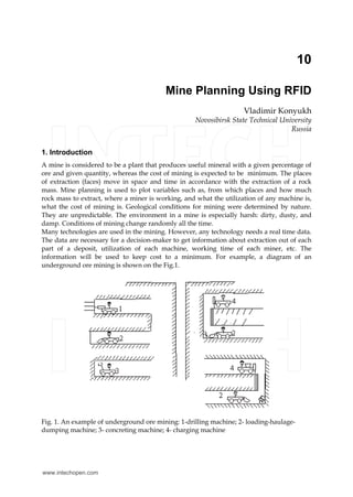
information will be used to keep cost to a minimum. For example, a diagram of an
underground ore mining is shown on the Fig.1.
Fig. 1. An example of underground ore mining: 1-drilling machine; 2- loading-haulage-
dumping machine; 3- concreting machine; 4- charging machine
www.intechopen.com
2. Deploying RFID – Challenges, Solutions, and Open Issues180
The roadways are developed by drilling (1) and charging (4) machines to get access to
deposits of ore. After blasting, a concreting machine (3) prepares a roadway. Other drilling
and charging machines prepare an extraction chamber. After blasting the rock mass is
transported by mobile loading- haulage-dumping machines with a bucket (2) on the
distance 30-100 meters to a dumping place.
Many questions for management are not clear enough, such as:
• how much rock mass was delivered from each face;
• what the state of each face is ;
• what condition mine machines are ;
• how long each machine is working;
• who is the driver of each machine;
• what is the utilization of each machine in the mine ;
• where is each miner at present;
• what is the distribution of mine machines in the mine.
To answer such questions, reliable sources of information are necessary.
2. Problems of mine planning
2.1 Surface mining
The shovels, which extract a rock mass, are distributed in a space. Extracted rock mass is
transported by trucks to refinery, storage or waste. For example, the layout of an open pit
mine is shown in Fig.2.
Fig. 2. Mining at an open pit mine
Both shovels and trucks are historically various and have a high cost. That is why the
full utilization of shovels and trucks in the system “ N shovels - M trucks” is actual for
surface mining first. It is actually for management to get current information about trucks
and shovels to improve the work of the open pit mine. There were many efforts to
determine placement of the trucks and shovels by using a Global Positioning System
(GPS), to measure the load of a truck by vibration of body, and to identify a truck by bar-
coding. Unfortunately, these ways are difficult and have many limitations for mine
planning.
A dispatcher of an open pit mine would like to get the following information:
Refinery
Storage
Waste
www.intechopen.com
3. Mine Planning Using RFID 181
• ID of i-th ( i=1,M) truck;
• ID of j-th ( j=1, M) driver of the truck;
• ID of k-th ( k=1,N) shovel;
• ID of k-th ( k=1, M) of the shovel’s driver;
• ID of the dumping place;
• current load of i-th truck;
• starting point of i-th truck;
• finish point of i-th truck;
• time of i-th truck’s arrival from a known starting point;
• time of i-th truck’s departure to a known finishing point;
• quantity of fuel in a i-th truck;
• what a condition of k-th shovel ( waiting, loading of rock mass into a back, breakage) is;
• what a condition of i-th truck ( movement with rock mass, movement without rock
mass, refueling, breakage, loading, dumping, waiting) is;
• what number of trips has the i-th truck taken;
• what number of k-th shovel’s buckets were carried by i-th truck.
If the truck situated in loading zone, the shovel loads the truck by several scooping. The
number of scooping depends on many factors.
A total time of working cycle Ts for the each machine consists of two parts:
Ts = Tw + Td,
where Tw=working time of k-th shovel;
Td = idle time of k-th shovel.
Using this information, management could get the following indices to improve the activity
of the open pit mine:
-the utilization of the i-th truck
1
1
( )
Li
lw
l
i
Li
w d l
l
T
K
T T
=
+
=
=
,
where Li =number of trips for i-th truck;
Tw =working time of l-th trip for the i-th truck;
Ts= total time (including idle time) of l-th trip for the i-th truck;
-accumulated working time of i-th truck
Ai=
1
Li
l
l
T
=
;
-the utilization of the k-th shovel
www.intechopen.com
4. Deploying RFID – Challenges, Solutions, and Open Issues182
1
1
( )
G V
gv
g v l
k
G
w s g
g
T
K
T T
= =
=
=
+
,
where g= (1,G)-number of the shovel’s working cycles;
v= (1, V) = average number of shovel’s buckets to load the i-th truck;
Tgv =working time for v-th loading cycle;
-accumulated working time of the k-th shovel
1
G V
k gv
g v l
B T
= =
= ;
-need for fuel for the i-th truck
1
L
i
l
lQ q
=
= ,
where lq = consumption for fuel for the l-th trip;
-need for energy for the k-th shovel
1
G
k
g
gE q
=
= ,
where gq = consumption for energy of the k-th shovel;
-distribution of energy between machines;
-cost of mining;
-quantity of rock mass that was extracted from various places in a deposit;
-placement of each person at mine;
-working time of each person at mine.
Thus, an on-board medium source must keep the following information about a truck (table 1).
Information Regularity Use for mine planning
ID of a truck Shift All trucks on the open pit mine
ID of a truck’s driver Shift Assigning of a driver to a truck
State of a truck Every
hour
Utilization of a truck
Quantity of fuel inside a
truck’s tank
Every
hour
Need for fuel for a truck
Working time of a truck Current Accumulated working time for maintenance
Load of a truck’s body Every trip Accumulated quantity of extracted rock mass
Place of dumping Every trip Distribution of rock mass between a refinery,
storage, and wastes
Number of a trip Every trip Comparison of a trucks’ utilization
Table 1. Information about a truck
www.intechopen.com
5. Mine Planning Using RFID 183
Other mobile objects, such as a drilling machine, must store and transfer various
information for a dispatcher (at least the ID of a machine, its placement, its condition, and
duration of its work). Current information about the placement of each working person is
necessary for efficient management of the open pit mine.
2.2 Underground coal mining
The most widespread technology of coal mining is shown on the Figure 3.
Fig. 3. Technology of coal mining at a fully - mechanized face
A shearer (1 ) extracts of a strip of coal, moving on a metal conveyor (2). At the same time,
support units (3) are drawn up a face. The metal conveyor delivers extracted coal to a
conveyor network (4). An underground train (5) is loaded under a bin (6).After loading an
underground train transports the coal to a shaft (7). Then the coal is lifted by a skip (8) to the
surface.
Many underground roadways for ventilation and transportation are inside an underground
mine. Some of them are abandoned, some roadways are in development. All roadways form
an underground network.
At present, some information about current work is transferred by a team-leader by
telephone. Objective information in real time will improve mine planning (table 2).
Planning at the mine will be more effective because new information can be acquired on the
basis of the initial data:
-utilization of j-th mobile machine at i-th face
1
1
( )
G
wg
g
j
G
w s g
g
T
K
T T
=
=
=
+
,
www.intechopen.com
6. Deploying RFID – Challenges, Solutions, and Open Issues184
Information Regularity Use for mine planning
ID of the i-th ( i=1; n) face
All the
time
State of the mine
State of the i-th ( i=1; n) face (work, stoppage) Every hour Re-distribution of faces
Quantity of coal, that was extracted out of the
i-th face
Every shift
Comparison of faces,
output of the mine
State of k-th machine ( work, stoppage or
breakage)
Every hour
Utilization of j-th mobile
machine, timely repair
State work, stoppage, breakage of k-th
stationary machine
Every hour
Utilization of k-th
stationary machine,
timely repair
Grade of the bin’s filling
All the
time
Utilization of the bin
Placement of the underground train: on the
way to the dumping place, on the way to the
loading place, in front of the dumping place,
in front of the loading place
All the
time
Control of transportation
Condition of the underground train: under a
loading, under a dumping, movement,
waiting, breakage
All the
time
Control of transportation
ID of each miner during the working shift for
the i-th face
Twice in
the shift
Calculation of working
time, identification in
cases of accidents
ID of each miner in the various places of the
mine
Twice in
the shift
Calculation of working
time, identification in
cases of accidents
Placement of miners in the mine Every hour
Calculation of working
time, identification in
cases of accidents
Table 2. The initial data about underground coal mining
where g= (1,G)-number of the machine’s working cycles;
Tw =working time in g-th working cycle;
Ts= total time (including idle times) of the g-th working cycle;
-utilization of k-th stationary machine at i-th face
1
1
( )
G
wg
g
k
G
w s g
g
T
K
T T
=
=
=
+
,
where g= (1, G)-number of the working cycles;
Tw =working time for the g-th working cycle;
Ts=total time (including idle times) of the g-th working cycle;
www.intechopen.com
7. Mine Planning Using RFID 185
-accumulated working time of the j-th mobile machine
Aj=
1
G
wg
g
T
=
;
-accumulated working time of the k-th stationary machine
Ak=
1
G
wg
g
T
=
;
-need for energy for the i-th face
1 1
JK
i k j
k j
Q q q
= =
= + ,
where K= number of stationary machines in the i-th face;
J=number of mobile machines in the i-th face;
-distribution for energy between faces;
-time-table of trains’ movement,
-load of a train,
-number of trains for each placement of mining
-cost of mining;
-quantity of rock mass, that was extracted out of various places of a deposit;
-working time of each person at the mine.
Managers of the mine will be able to organize mining at a minimum cost.
2.3 Underground ore mining
The widespread technology of ore mining by extraction chambers is shown in the Figure 4.
Fig. 4. Underground mining at an ore mine: 1- a roadway for ventilation and drilling
machine; 2- a loading-haulage-dumping machine (LHD); 3- a roadway for transportation by
LHD; 4- a dumping place; 5- an underground train; 6- a skip for lifting of rock mass; 7- shaft.
www.intechopen.com
8. Deploying RFID – Challenges, Solutions, and Open Issues186
First, many vertical boreholes (40-60 meters long) are drilled from a drilling roadway (1)
( Fig. 4 ). Then the boreholes are charged by explosive partially. After the blasting the ore
mass drops to the bottom of a chamber. After that, a diesel Loading-Haulage-Dumping
machine (LHD) (2) scoops the rock mass and transports it via roadway (3) for a distance 50-
100 m to a dumping place (4). Finally, an underground train (5) transports the ore mass to
the shaft (7). The rock mass is lifted by skip (6) to surface for refinery. A percentage of useful
mineral for a chamber is variable. As a rule, one is known before.
The problem is- how to distribute extraction between the chambers to ensure the given
percentage for ore mass on output of the mine. All of mobile machines are attached to the
chamber. A behavior of a chamber without extraction is unpredictable.
The following data can be extracted during current work of the mine (table 3).
After preparation of the initial data, a manager of the mine can determine:
-utilization of i-th LHD-machine for the j-th extraction chamber
1
1
( )
G
wg
g
i
G
w s g
g
T
K
T T
=
=
=
+
,
where g= (1,G)-number of the machine’s working cycles;
Tw =working time in g-th working cycle;
Ts= total time (including idle times) of the g-th working cycle;
-utilization of k-th train
1
1
( )
N
wn
n
k
N
w s g
n
T
K
T T
=
=
=
+
,
where n= (1,N)-number of trips for k-th train;
Tv =working time for the n-th trip;
Tf=time of the n-th trip;
-accumulated working time of the i-th LHD-machine
Ai=
1
G
wg
g
T
=
-accumulated working time of the k-th train
Ak=
1
N
wn
n
T
=
;
-need for fuel for the i-th LHD-machine
1
G
i g
g
Q q
=
= ,
where qg=fuel consumption for g-th trip of i-th LHD-machine;
www.intechopen.com
9. Mine Planning Using RFID 187
Information Regularity Use for mine planning
ID of the i-th ( i=1; n) mobile machine Start of the
shift
Consideration of
machines,
ID of the driver on i-th ( i=1; n) mobile machine Start of the
shift
Consideration of drivers,
permission for driving
Placement of the i-th ( i=1; n) mobile machine All the time Control of mining
State of j-th mobile machine: work, stoppage or
breakage
All the time Utilization of the
machine
State ( work, stoppage, breakage) of k-th
stationary machine
All the time Utilization of the
machine
Quantity of rock mass that was extracted out of
a j-th chamber for the trip of the i-th ( i=1; n)
mobile machine
Each trip Output of the i-th ( i=1;
n) mobile machine
Quantity of rock mass, that was delivered to a
dumping place after a trip of LHD
Each trip Calculation of rock mass
Total quantity of rock mass that was extracted
out of a j-th extraction chamber
Finish of the
shift
Output of the mine
Grade of the bin’s filling All the time Utilization of the bin
State of the underground train : loading,
movement to the shift , movement to the bin ,
dumping, breakage
All the time Utilization of the train
ID of a miners in the various places of the mine Start and
finish of the
shift
Calculation of working
time, identification in
case of accident
Placement of miners in the mine Every hour Calculation of working
time, identification in
case of accident
ID of a miners in the j-th face Start and
finish of the
shift
Calculation of working
time, identification in
case of accident
Quantity of explosive that was expended for the
j-th extraction chamber
After blasting Need for materials
Percentage of dangerous gases inside the j-th
extraction chamber
All the time Danger warning
Placement of the underground train: on the way
to the dumping place, on the way to the loading
place, in front of the dumping place, in front of
the loading place
All the time Control of transporting
ID of the train on the mine Start of the
shift
Utilization of the train
State of the underground train: under a loading,
under a dumping, movement, waiting, breakage
All the time Control of transporting
Volume of fuel for i-th ( i=1; n) mobile machine All the time Need for fuel for the i-th
( i=1; n) mobile machine
Table 3. The initial data about underground ore mining
www.intechopen.com
10. Deploying RFID – Challenges, Solutions, and Open Issues188
-distribution for fuel for LHD-machine between places of extraction;
-time-table of train movement,
-load of a train,
-dynamics of rock mass extraction out of the j-th extraction chamber;
-number of trains needed for each place of mining;
-cost;
-quantity of rock mass extracted from various places in a mine;
-working time of each person at mine.
As a result, the more effective work, e.g. a redistribution of LHD-routes can be organized
according to the concentration of desirable minerals in various places of the deposit.
2.4 Delivery of supplies to distributed underground faces
The distributed faces need the various supplies from the surface to continue mining. At
present, a number of supplies loads, such as support units, are delivered from surface
storage to a face with the aid of a shaft dropping, transporting by underground rail train,
and transporting by winches (Fig.5).
Fig. 5. Existing delivery of loads to distributed faces: 1- underground storage; 2-rail train; 3-
winches
1 2
3
3
3
3 3
Surface storage
www.intechopen.com
11. Mine Planning Using RFID 189
The disadvantage of such delivery is the long delay in delivery of supplies to a face. Besides,
subjective mistakes for distribution of supplies between faces take place. Underground faces
move all the time. A limited space and movement of a face do not permit to have an own
storage for a face. Equipping of supplies by medium sources makes it possible, to ensure a
face by necessary supplies in “Just-In-Time”- mode (Krieg, 2005).
3. Mobile objects in mining
Moving mine faces require mobile objects. Let’s describe some peculiarities of such objects
from the point-of-view of mine planning.
It is necessary to know where each miner is in real-time. Consequently, each miner must
have an ID. Many ID-readers must be distributed on the pathways miners and connected
to the surface via an information network. Mine machines and dangerous places must
determine the ID of a miner. Every miner must wear a helmet (hard hat) ( Fig. 6 ).
Fig. 6. A miner as a mobile object for mine planning
A helmet is the most suitable place for a medium source that must be cheap, light, and
stable to harsh environment. Its capacity may be small. A mine has up to 1000 miners. In
underground mining, every miner has a lamp with a battery pack in addition to a helmet.
A truck moves on the fixed road during surface mining (Fig.7). To make a decision about a
distribution of trucks, a dispatcher would like to know ID of a machine, ID of a driver, a fuel
need, time of loading, movement, and dumping, start and finish points of movement,
current load, and placement on a pit mine, and state of a truck. A medium source will work
in harsh conditions, with natural temperature, under metal environment. An open pit mine
has until 50 trucks.
(a) (b)
Fig. 7. A truck for surface mining: a- without rock mass; b- with rock mass
www.intechopen.com
12. Deploying RFID – Challenges, Solutions, and Open Issues190
There are many mobile machines for underground mining, such as a Loading-Haulage-
Dumping Machine (Fig. 8).
Fig. 8. Loading-Haulage-Dumping Machine as an example of mine machine for
underground ore mining
An underground mine has up to 50 such machines. As a rule, a Loading-Haulage-Dumping
machine has a diesel drive and rotating bucket.
A surface dispatcher would like to know ID of the machine, ID of the driver, current fullness
of the bucket, the fuel need of each truck, current placement and state of each machine, time
for each trip. An on-board medium source should work in metal environment and harsh
conditions.
4. Identification of mobile objects
Like identification of mobile objects in industry, such decision is the obvious application of
miners’ identification (Wilma’s, 2009). A miner has an own transponder, that is placed on a
miner’s helmet or on a battery pack (Fig. 9).
Fig. 9. Identification of a miner
A transponder can be used for identification of other mobile objects. ID of an object is
written into a transponder. Stationary RFID-readers with RFID- antennas are connected
with the information network and placed in various points of a working zone. If a mobile
object moves near an RFID-antenna, the data about his ID and placement have been
introduced into the information network (Fig. 10).
RFID-reader
Information network Transponder
on a helmet
www.intechopen.com
13. Mine Planning Using RFID 191
Fig. 10. Information accompaniment of a mobile object
It makes it possible to determine the time of arrival to working place; time of work’s finish,
placement of a miner at present; give permission for control of a machine.
Additional information can be derived on the basis of the data:
• how long did each miner work?
• where is a miner after his shift?
• how long was each machine used?
• by which miner was driven each machine?
• was access to the machine permitted for the miner?
• who is left in an emergency zone at present?
This information makes it possible to discover the placement of any miner, calculate his
working time, and identify a miner in case of accident. The decision could be applicable also
for other mobile objects in mining (Spadavecchia, 2007). An RFID-reader can read a
vehicle’s ID and switch a color-light signal in front of a crossroads. Many RFID-readers on
the way of a vehicle can form its route.
5. Requirements to medium sources for mine planning
Many peculiarities of mining make special demands on medium sources.
A transponder for surface mining will be able to work in a natural temperature ranging
from -50 ° C up to +50° C. A transponder for underground mining will be able to work in a
temperature ranging from 0° C up to + 50° C.
Mostly an underground roadway is up to 4 meters wide. That is why the distance between a
mobile object and an antenna is up to 3. 5 meters. The same distance is required for surface
mining.
Mine environment is especially damp, dusty, and dirty. An on-board medium source will be
able to work in metal environment with electromagnetic violence.
Mostly mobile machines work individually. That is why anti-collision prevention is
necessary for miners mainly. However, sometimes it is necessary to determine, how many
machines are situated together, e.g. inside a repair shop.
A transponder to identify a mobile object must keep information about the ID of the object
only. It is enough to have a capacity app. 1 Kb.
Mobile object
On-board
transponder
RFID-
antenna
RFID-reader
Information network
www.intechopen.com
14. Deploying RFID – Challenges, Solutions, and Open Issues192
A storage capacity to add information about current mining must be up to 200 Kb. Such
information will be written up to 100 times per shift and will be kept at least for one month.
The speed of mobile objects during underground mining is up to 1 meter per second. The
data for mine planning are mostly constant. The distance between distributed stationary
readers must be app.50 meters. The information network must be applicable for many
readers, which could be work at the same time.
There are app. 150 mobile machines at a mine. A mine machine has the high cost. That is
why; an on-board medium source can be expensive also. The information in a transponder
must be protected against non-permitted access and non-permitted rewriting to avoid
intentional falsification. A transponder in front of an emergency zone must be intended not
only for a miner, but also for a mobile machine.
The acquired information must be complete to reduce cost, close down exhausted areas of
deposit and mine new areas of a deposit, stabilize the percentage of useful mineral for a
customer, plan the maintenance of mine machines, determine requirements of machines
for development of mining, and etc.
6. A mobile mine machine as the data medium
If a mobile machine has an on-board RFID-writer and other mobile objects have on-board
transponders, one can determine the way to continue a movement at underground
crossroads, determine a miner or another machine in front of the location the mobile
machine. It is difficult to get data out of moving working places. A mobile machine with an
on-board sensor, transponder, and RFID-writer is suggested by the data on current mining.
There are no limitations for the transponder’s size.
We suggest using a mobile machine with RFID-writer that writes current information from
an on-board sensor to an on-board transponder (Fig. 11).
Fig. 11. Delivery of underground information from a mobile object to RFID-reader
A stationary RFID-antenna is placed on a wall of the roadway. The information from a
mobile object is transferred to the RFID-reader, and then is introduced to the information
network, which connects the distributed moving medium sources with an information
centre on the surface (Fig. 12).
www.intechopen.com
15. Mine Planning Using RFID 193
Fig. 12. Connection of underground RFID-readers with an information centre 5 on surface:
1-drilling machine; 2- loading-haulage-dumping machine; 3- shotcreting machine; 4-
charging machine
The on-board RW-transponder can collect the data of various sensors to read not only
current information but also track that accumulate a quantity of extracted rock mass.
Besides, one must keep track of the ID of the various machines.
7. Reliability of primary information
To transfer primary information about current mining, a reliable information network must
be introduced. Methodology of the volume balance can be used to have reliable information
for mine planning.
m n
=1 =1
i j
i j
a b= ,
where
=1
m
i
i
a = quantity of rock mass, that was extracted out of m distributed faces;
1
n
j
j
b
=
=
quantity of rock mass, that was delivered to storages of mine.
This is estimated on the condition, that extracted rock mass has no addition or loss on the
way to a dump.
Besides, the time from between the start of work at a face and appearance of each load at a
dump must be calculated and compared with real time.
8. Total planning of mining for the mine
The structure of mine planning can be compared to a manufacturing planning. “Computer
Integrated Manufacturing” is a plant that fulfills some orders of customers. One consists of
www.intechopen.com
16. Deploying RFID – Challenges, Solutions, and Open Issues194
standards “Manufacturing Resources Planning,” “Manufacturing Execution System,”
“Supervisory Control And Data Acquisition,” “Control,” and “Input/Output” (Knuth,
2005). All standards are exchanged by information in real-time.
“Computer Integrated Mining” consists of “Mine’s Resources Planning,” “Mining
Execution System”, “Supervisory Control And Data Acquisition”. Two lower standards
“Input/Output” and “Control” are necessary for control only.
At first, orders for useful minerals are analyzed by management of mine on the standard
“Mine’s Resources Planning”
( Fig.13).
Fig. 13. Standards of mine planning
Managers on the standard “Mine’s Resources Planning” evaluate the potentiality of the
mine to fulfill a received order. They plan the development of the mine: existing places,
Supervisory Control And Data Acquisition
Mining Execution System
Mine’s Resources Planning
Order for useful
mineral
… …1-st source of
data
1-st object
i-th source оf
data
i-th object
N-th source of
data
N-th object
www.intechopen.com
17. Mine Planning Using RFID 195
abandoned places, and new places for mining. In addition, managers plan a changing of a
machine, maintenance of mine machines, need for energy, need for materials, need for labor,
etc. Decision-makers need various information about current mining (table 4).
Information Regularity Effect for mine planning
Current places of mining A month Evaluation of current state of mining
Abandoned places of
mining
A month Control of abandoned places
Perspective places of
mining
A month Development of the mine
Percentage of ore in
extracted rock mass
A shift
Preparation of a refinery, discharge of a
customer’s order
Energy consumption for
distributed places
A shift Planning of need for energy sources
Distribution of materials
consumption
A shift
Order of materials for distributed
working places
Cost of mining A month Comparison with the current cost
Accumulated working
time of a machine
Time of a
working cycle
Planning of a energy consumption,
maintenance, and replacement of a
machine
Accumulated working
time of a miner
A shift Calculation of earnings
Orders of distributed
places for materials
An hour Distribution of materials
Table 4. Information for the standard “Mine’s Resources Planning “
Energy consumption for j-th place of mining is calculated automatically as
1
( ) ( )
n
j i
i
E T E T
=
= ,
where ( )iE T = energy consumption by i-th machine for the period T; n= number of
machines for j-th place of mining.
Need for k-th kind of materials (explosive, cables, pipes, etc.) for the mine is calculated as
1 1
( )
m K
K jk
j k
S T S
= =
= .
Plans for the mine should be corrected according to current orders out of distributed faces.
Cost of mining is summarized as the share expenditures on working powers, energy,
materials, amortization, etc.
Accumulated working time of a machine is necessary to replace machines workout:
0
w
i p
p
T t
=
= ,
where W= summary working time of i-th machine.
www.intechopen.com
18. Deploying RFID – Challenges, Solutions, and Open Issues196
Accumulated working time of α-th miner is necessary to determine the earnings of α-th
miner:
0
( )
F
i
i
P p nα ×
=
= ,
where pi= hour’s earnings of α-th miner; n= (0;F) = number of working hours for α-th miner.
Analyzing current information about the activity of the mine, a manager is able to re-distribute
the mobile machines between places of mining, re-distribute teams of miners for a working
shift, change the faces according to a current order, re-distribute the working shifts, etc.
9. Reflection of current mining
It is necessary for a dispatcher, to observe the current activity in a mine. To realize it, a
Supervisory Control And Data Acquisition (SCADA system) is used. The existing SCADA-
packages, such as In Touch®, can be adapted to the mine. The self-designed SCADA-system
can be developed for the mine also. The development of the own SCADA-system is cheaper,
but depends on developers of the mine.
There are static and dynamic information about current mining. Static information consists
of the plan of the mine; the placement of stationary equipment, network of communications,
placement of faces, some inscriptions. Dynamic information consists of current data about
the mine: the state of any face (work or idle time), output of any face, state of any mobile
object, current placement of any mobile machines; fullness of any bin. For example, the open
pit mine is presented on a screen (Fig. 14).
UTILIZATION OF SHOVEL: 86.67 %
WRITING TRUCKS
ACTUAL : 1
AVERAGE : 0.7
AVERAGE TIME : 1.7
WRITING TRUCKS
ACTUAL : 2
AVERAGE : 1.2
AVERAGE TIME : 3.1
2 n d Belt
1 s t Belt
Main Silo
3250.00
322.74
Surge Silo
322.7
Fig. 14. Reflection of the open pit mine in USA ( Sturgul, 1995)
www.intechopen.com
19. Mine Planning Using RFID 197
Static information is the placement of shovel, silos, belts, railway, and inscriptions.
Dynamic information is placement of trucks, state of the shovel, number of empty and
loaded trucks, utilization of the shovel, time of the trip, filling of the silos, and load of the
belts.
Аt first, static information must be constructed on a dispatcher’s screen (table 5).
Information Details Accuracy
Scheme of the mine no required ± 10 m
Places of loading no required ± 10 m
Places of unloading no required ± 10 m
Network of existing faces no required ± 10 m
Network of abandoned faces no required ± 10 m
Network of communications no required ± 10 m
Transport network no required ± 10 m
Placement of the stationary machines no required ± 10 m
Various tables standard standard
Various inscriptions standard standard
Table 5. Static information for a dispatcher’s screen
Then dynamic information about current time, output of the face, current plan’s execution,
pre-recognition of future accidents, and support of operative decisions in case of accidents is
presented on a screen in real-time mode (table 6).
Information Regularity Reflection
State of a face Every hour Color of a face
Distribution of mobile objects Every 15 minutes Placement on the network
Output of a face Every hour Current data
Time of a working cycle Each working cycle Data
Output of the part of the mine Each shift Data
Fullness of every bin Every 15 minutes Full part of bin
State of the transport machine Each trip Color of a machine
Table 6. Dynamic information for visualization of current mining
Information is changed on a dispatcher’s screen by introduction of global variables (by tags).
Connection of medium sources with virtual reflection of mining is realized using OLE for
Process Control (OPC).
The main rule for visualization is that the information must be enough to make a decision
about improvement of current mining. For example, a decision-maker can compare the
activity in various places of the mine.
Watching current mining information, a dispatcher can step and call the concrete persons,
such as a team’s leader to clear the matter up. The SCADA-system recognizes pre-accident
situations in good time and notifies about beginning violations in normal work of the mine.
If a random accident takes place, the SCADA-system produces recommendations to a
dispatcher, who can prevent a deterioration of the situation , e.g. localize a random fire in
various places of the mine.
www.intechopen.com
20. Deploying RFID – Challenges, Solutions, and Open Issues198
As well as current information, the SCADA-system keeps detailed information about past
mining, such as utilization of a mine machine. Comparison of current information with
former information can improve the current mining.
Using this system, the information about total working time, expenses of energy, total
output, utilization of mobile objects, and utilization of bins can be acquired for managers of
the mine.
10. Mining execution system
The system is geared to control execution of shift planning and prepare information for the
standard “Mine’s Resources Planning “.
Sometimes mine equipment units have failures. Breakages lead to random refusals of a total
technological chain.
Mining Execution System (MES) redistributes the faces and mine machines to ensure the
same output of mine. The standard needs current information about mining (table 7).
Information Regularity Effect for mine planning
Output of a face All the time Contribution of a face to the mine’s output
State of a face All the time Re-distribution of mining’s places
Working time of a face All the time Fulfillment of a face’s plan
State of a machine All the time Control of mining
Working time of a machine All the time Planning of maintenance
Placement of a machine All the time Planning of mining
Placement of miners All the time Planning of miners’ distribution
Working time of a miner All the time Evaluation of miner’s use
Fulfillment of a mine’s plan All the time Evaluation of plan’s fulfillment
Real time All the time Evaluation of the shift’s time
Table 7. Information for “Mining Execution System”
Using this information, a mine dispatcher can determine how to maintain output during of
unpredictable situations.
11. Suitability of RFID for mine planning
Optical character recognition needs comparison with a model. Random forms of objects,
such as surge pile of rock mass make this impossible for mining. Infrared identification is
not applicable for mining, because there is limited potential for a changing environment,
requires the line of sight between a transmitter and receiver of information, needs
comparison with a pattern. Bar coding has no protection to soiling and can not be attached
by new information.
As a rule, voice sources of information are in use for mine planning. Voice sources are non-
exact and non-reliable for mine planning.
Mobile data mediums on the basis of RFID produce many opportunities for mine planning.
RFID- system can work under the harsh mine environment and does not require the light-of
–sight between a transponder and a writer. Active transponders can be read at great
distances. It is an obvious use of an RFID- system for identification and positioning of
mobile objects.
www.intechopen.com
21. Mine Planning Using RFID 199
Some mines introduce RFID to identify miners (RFID for Mining, 2008), like identification of
goods in commerce. Many transponders can be read at once. Nobody can avoid being
identifies before work. RFID-systems present the data in real time. It is impossible to forge
information inside a transponder.
The possibility exists to add information and use machines to deliver data about working
places in real time. Active transponders for mine applications may be smart. RFID- systems
have no moving parts and do not require regular maintenance.
However, all miners must be informed in case of an accident. RFID may not be used to
transfer accident information. The special design of RFID- system for a metal, dirty, and
dusty environment is necessary. A mine must be equipped with an information network.
Underground mines for coal mining require special permission to use RFID-system in an
explosion-dangerous environment.
12. Towards intellectual mining
Deposits of useful minerals that were easily accessible for traditional mining are exhausted
already. Historically, an underground mine is dangerous and unpleasant for miners. At
present, the average depth of mines is 1200 meters. The deeper a mine is, the worse and
more dangerous miners’ work is and the more expensive miners’ work is. The high
temperature of the Earth’s centre raises the temperature of the underground mine and it will
be impossible to work.
It is too hard to co-ordinate underground mining actions in space and time. There are idle
times of underground equipment owing to inadequate information about current mining.
Employers waste a lot of money transporting miners for underground work.
The long-term dream of mining engineers is to be able to mine without underground
miners. The main idea is – the control of underground machines from the surface (Fig. 15).
Fig. 15. Underground mining without underground drivers: 1-drilling machine; 2- loading—
haulage-dumping machine; 3- shotcreting machine; 4- charging machine; 5- drivers’ box
www.intechopen.com
22. Deploying RFID – Challenges, Solutions, and Open Issues200
A console for remote control is situated in front of a working place. One is connected via an
underground information network with the driver’s box on surface. Mobile mine machines
move along a guideline, which is placed in roadways. A driver observes a working place as
if he is on a machine and transfers control commands to the machine. Each of the mine
machines is equipped with an on-board receiver.
A broadband information network is the backbone of future mining. Such a network must
transfer video, audio, and data information from distributed working places to the surface
and back.
A machine in intellectual mine can adapt itself to changing working conditions: to change
positions of working heads, direction of movement, step size of a roof support, and speed of
a roof support. Such opportunities will make it possible to avoid some geological hazards,
avoid dangerous rock pressure manifestations, stabilize the quality of mining, and increase
the utilization of machinery. Existing information networks for voice exchange is not
available for intellectual mining because the control of an autonomous machine in real-time
needs a broad transmission band for video information.
Information network for a future mine could be used not only for remote control of
underground machines, but also for mine planning using RFID.
As the long-term, an RFID-system for mining on other planets without direct visibility of a
working place can be created.
13. System approach to use RFID for mine planning
The main idea of system approach consists of the creation of elements for the future system
using step-by-step development. Each element will be included in a future system later
without changes.
An RFID-system will be included in future mining that is based on control without direct
visibility. How to transfer current information about mining to management of the mine?
Many distributed working places are moving all the time during mining.
The existing information network in a mine was created for telephonic communication only
which has a narrow communication band. Probably, transmission of data information via
such a network will be incorrect for future mine planning.
A distributed information network for a future mine must transfer video information in
real time mode to a remote driver. That is why one must connect moving transmitters with
stationary receivers and be broad- band. Later, the network for future mining will be used
for transferring information from on-board transponders without additional expense.
14. Need for research on the way to mine planning using RFID
It is necessary to test the RFID- system for the harsh mine environment that is metal, dirty,
dusty, and damp.
An on-board RFID-writer for a suitable mine machine must be selected. One should have
input for a sensor and output for the transponder. Existing telephonic network must be
tested for suitability to transfer data information from the transponder.
The influence of random electromagnetic interference on RFID-system must be evaluated.
Placement of RFID-writer and RFID-transponder on a mine machine must be carefully
chosen. The packages must be developed for each stage of mine planning. A human-
machine interface must be developed for the visualization of current mining.
www.intechopen.com
23. Mine Planning Using RFID 201
15. Conclusion
Mining has many peculiarities to get reliable information for mine planning. Environment
for a data medium is humid, dirty, and dusty. Mine machines are metal. Working places are
distributed in a space and move all the time. At present, RFID is used for identification of
miners only, like identification of moving goods using EPC.
The connection of a sensor on a mobile object allows an RFID-writer to develop new
potential for RFID-applications in mine planning.
Such a mobile data medium allows the gathering of various information: current reports about
an extraction in various places of a deposit, placement of mobile objects during mining in real
time, avoidance of non-permitted access to control, acquisition of full information about
current mining, warning about emergency situations, and etc. An RFID-system can be used to
visualize the placement of machines along roadways; to monitor miners with personal
transponders; to prevent non-permitted control of machines; to give priority control of
machines; to evaluate productivity of both machines and mining areas; to evaluate fuel
consumption and machine resources. This information can be used for management of the
mine.
16. Acknowledgment
This work is supported by the Russian Foundation of Basic Researches, grant № 10-08-
01211-а “Modeling of mining on deep mines” and the State Program “Joining of Science and
High Education in Russia for 2002-2006”, grant № U0043/995 “Preparation of experts in
information technologies for Kuzbass region”. Many thanks to my old friends Prof. J.Sturgul
and his wife Alison (Australia) for the thorough correction of English text.
17. References
Konyukh, V.; Tchaikovsky, E.& Rubtzova, E. (1988). Ways for the measurement of a
LHD- bucket filling during extraction of ore out of dangerous places. Physics-
technical problems of mining, No.2 (March-April1988), pp.67-73, ISSN 0015-3273 (in
Russ.).
Konyukh, V. (2005). Achievements in industrial automation and their possible applications
for underground mining, Proceedings of 14-th Int. Symp. on Mine Planning
and Equipment Selection (MPES2005), pp. 645-661, ISBN 093-0-9968-835-9, Canada,
Calgary, Sept. 16-20, 2005
Konyukh, V. (2010). Simulation of mining in the future, Proceedings of IASTED International
Conference on Control, Diagnostics, and Automation (ACIT 2010), рр.1-6, ISBN 078-0-
88986-842-7, Novosibirsk, Russia, June 15-18, 2010
Krieg, G. (2005). Kanban-Controlled Manufacturing Systems, Springer-Verlag, ISBN 3-540-
22999-X, Berlin Heidelberg
Wilma’s, C. (2009). Applying active RFID in mining, In: Instrumentation and Control, 1 Jan.
2009, Available from www.instrumentation.co.za/papers/C9205.pdf
Spadavecchia, O. ( 2007). RFID technology searching for more mining applications, In:
Mining weekly, 13th April 2007, Available from www.miningweekly.com
RFID for Mining (2008). Available from www.falkensecurenetworks.com
www.intechopen.com
24. Deploying RFID – Challenges, Solutions, and Open Issues202
Sturgul, J. (1995). Simulation and animation: come of age in mining , In: Engineering and
Mining Journal, October 1995, pp.17-19.
www.intechopen.com
25. Deploying RFID - Challenges, Solutions, and Open Issues
Edited by Dr. Cristina Turcu
ISBN 978-953-307-380-4
Hard cover, 382 pages
Publisher InTech
Published online 17, August, 2011
Published in print edition August, 2011
InTech Europe
University Campus STeP Ri
Slavka Krautzeka 83/A
51000 Rijeka, Croatia
Phone: +385 (51) 770 447
Fax: +385 (51) 686 166
www.intechopen.com
InTech China
Unit 405, Office Block, Hotel Equatorial Shanghai
No.65, Yan An Road (West), Shanghai, 200040, China
Phone: +86-21-62489820
Fax: +86-21-62489821
Radio frequency identification (RFID) is a technology that is rapidly gaining popularity due to its several
benefits in a wide area of applications like inventory tracking, supply chain management, automated
manufacturing, healthcare, etc. The benefits of implementing RFID technologies can be seen in terms of
efficiency (increased speed in production, reduced shrinkage, lower error rates, improved asset tracking etc.)
or effectiveness (services that companies provide to the customers). Leading to considerable operational and
strategic benefits, RFID technology continues to bring new levels of intelligence and information, strengthening
the experience of all participants in this research domain, and serving as a valuable authentication technology.
We hope this book will be useful for engineers, researchers and industry personnel, and provide them with
some new ideas to address current and future issues they might be facing.
How to reference
In order to correctly reference this scholarly work, feel free to copy and paste the following:
Vladimir Konyukh (2011). Mine Planning Using RFID, Deploying RFID - Challenges, Solutions, and Open
Issues, Dr. Cristina Turcu (Ed.), ISBN: 978-953-307-380-4, InTech, Available from:
http://www.intechopen.com/books/deploying-rfid-challenges-solutions-and-open-issues/mine-planning-using-
rfid