HX Controlador temperatura Hanyoung NUX (www.nammisa.com)
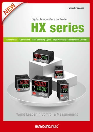
1. www.hynux.net
World Leader in Control & MeasurementWorld Leader in Control & MeasurementWorld Leader in Control & Measurement
Digital temperature controller
HX series
Economical Convenient Fast Sampling Cycle High Accuracy•Temperature Control
2. Digital temperature controller
It maintains the ease of use with its essential functionality for engineers and job-site
operators and high accuracy temperature control is achieved with fast sampling cycle
Economical • Convenient • Fast Sampling Cycle
High Accuracy Temperature Control
With the design of reducing the installation depth it
provides more space for installation and the control panel and control box
can be miniaturized
Installation Depth 63 ㎜
Thermocouple
RTD
Display accuracy
Multi input(sensor)
Control output
Control method
Display function
Sampling cycle
Relay / SSR / Current (4 - 20 ㎃) (available)
Retransmission Output (4 - 20 ㎃)
Display the process value (PV) and set value (SV)
together at the same time (4 digits)
Display temperature in celsius (℃) / fahrenheit (℉)
Display the position of decimal point (0.1/1 selectable)
Heating Control / Cooling Control
Simultaneous Heating ∙ Cooling Control
Measured Value, Set Value and Output Amount (selectable)
Simple selection
3. HX2 • HX3 • HX4 • HX7 • HX9
Digital temperature controller
▶ Multi-Input
(Thermocouple 12 type, RTD 2 type, DC Voltage 2 type)
▶ Multi-Output (Relay, S.S.R, Current Output)
▶ Retransmission Output (4 - 20 ㎃)
▶ Fast Sampling Cycle 62.5 ㎳
▶ Installation Depth 63 ㎜
▶ Heating Control / Cooling Control /
Simultaneous Heating ∙ Cooling Control
▶ Two Degrees of Freedom PID
▶ Heater Break Alarm
▶ Communication (RS485)
▶ Setting Value (SV) Selection by Contact Input (D.I)
Model Code Description
HX - Digital temperature controller
Dimension
2 HX2 : 48(W) × 96(H) ㎜
3 HX3 : 96(W) × 48(H) ㎜
4 HX4 : 48(W) × 48(H) ㎜
7 HX7 : 72(W) × 72(H) ㎜
9 HX9 : 96(W) × 96(H) ㎜
Control output
0 Normal (heating control)
1 Heating/cooling control (simultaneous control)
HX 2/3/9 option
0 None
1 RS485 communication + Heater break alarm (H.B.A)
HX7 option
0 None
1 RS485 communication + D.I 2 contacts (SV2, SV3)
HX4 option
0 None
1 RS485 communication + D.I 1 contact (SV2)
2 RS485 communication + Heater break alarm (H.B.A)
➜ Suffix code
❶ Process value (PV)
❷ Set value (SV)❼ Operation
Indicator
❻ Set key
❹ Down key
❸ Up key
❺ Shift key
➜ Part name and function
Number Name Description
❶ Process value (PV) Displays the process value in the operation mode
❷ Set value (SV) Displays the set value in the operation mode
❸ Up key
Increases the set value or used to move between
groups and to change an option in a parameter in
setting mode
❹ Down key
Decreases the set value or used to move between
groups and to change an option in a parameter in
setting mode
❺ Shift key Used to move the position of the digit
❻ Set key
Sets (confirm) the set value, displays the output amount, or
set an option in a parameter in setting mode and moves
between the parameters in a group. By pressing for 3
seconds, it enters the display setting mode (setting mode)
or returns to the operation mode
❼
Operation
Indicator
Lights when SV2 is displayed
Lights when SV3 is displayed
OUT1 indicator
OUT2 indicator
Auto-tuning indicator
Alarm 1 operation indicator
Alarm 2 operation indicator
4. Model HX4 HX3 HX7 HX2 HX9
Dimension
W X H X D (㎜)
48 X 48 X 63 96 X 48 X 63 72 X 72 X 63 48 X 96 X 63 96 X 96 X 63
Power supply 100 - 240 V a.c (±10 %), 50 - 60 ㎐
Power consumption 6 W max, 10 VA max
Input
Type Universal input
Sampling cycle 62.5 ㎳
Accuracy ±0.3 % of F.S (Depend on input type)
Allowable voltage Within ±20 V d.c (VDC), within ±10 V d.c (TC, RTD)
Reference junction
compensation accuracy
±3.5 ℃, 0 ~ 50 ℃
Operation after input break T.C : OFF, UP / DOWN RTD : UP
Control
output
Relay
N.O : 5 A 250 V a.c, 5 A 30 V d.c (resistive load)
N.C : 3 A 250 V a.c, 1 A 30 V d.c (resistive load)
S.S.R
(voltage pulse)
ON voltage : 12 V d.c min, OFF voltage : 0.1 V d.c max
Load resistance 600 Ω min
S.C.R
(current)
range : 4 – 20 ㎃ (±5 %), accuracy : ±0.2 ㎃
Load resistance 600 Ω max
Retransmission output
range : 4 – 20 ㎃ (±5 %), accuracy : ±0.2 ㎃
Load resistance 600 Ω max
Alarm output 5 A 250 V a.c, 5 A 30 V d.c (resistive load)
Contact input OFF resistance : 10 ㏀ min, ON resistance : 1 ㏀ max
Control
Method ON / OFF, P.I.D control
Output operation Reverse operation, Direct operation
Anti-reset windup Auto (A = 0), 0.1 ~ 100.0 %
Interface
Standard EIA RS 485
Max connection unit 31 units (but, ADDRESS setting : 1 ~ 99)
Communication method 2 wire half duplex
Data transmission asynchronous
Communication sequence None
Communication distance 1.2 ㎞ max
Communication Speed 2400, 4800, 9600, 14400, 19200 BPS (selectable by parameter)
Start bit 1 BIT
Data length 7 or 8 BIT
Parity bit NONE, EVEN, ODD
Stop bit 1 or 2 BIT
Protocol PC.LINK, PC.LINK SUM, MODBUS-ASCII, MODBUS-RTU
Response time Processing time in receiving + (response time x 10 ㎳)
2 degrees of freedom P.I.D 1 ~ 100 % of proportional band
Insulation resistance 20 ㏁ min (primary terminal – secondary terminal)
Dielectric strength 2,300 V a.c, for 1 minute (primary terminal – secondary terminal)
Operating ambient temperature 0 ~ 50 ℃, (with on condensation)
Operating ambient humidity 35 ~ 85 % R.H (with no condensation)
➜ Specification
5. Cycle Heater
S.S.RControl output
Sensor input
High display accuracy
Improved display accuracy
±0.3% of F.S (Full Scale)
Fast sampling cycle
Higher accuracy temperature control is
possible with the fast sampling cycle 62.5 ㎳
0.1℃ / 1℉ decimal point display
0.1℃ / 1℉ Decimal Point Display (℃) by internal parameter selection
Temperature Unit Selection in Celsius(℃) / Fahrenheit(℉)
62.5ms
±0.3 % of F.S
Actualized the highly accurate temperature controlling
HX2 • HX3 • HX4 • HX7 • HX9
6. HX9
HX4
HX
OU
RE
A
13
1
CT
OUT1
RELAY
SV2
SV3
OUT1
SSR/SCR
RET
OUT2
SSR/SCR
RET
A
B
B
TC
Current
Voltage
AL1
AL2
RTX(+)
RS485 RTX(-)
SG
13
14
15
16
1
2
3
4
5
7
8
10
11
12
22
23
24
9
19
20
21
17
6 18
POWER
100 - 240 V~ 50/60 Hz 5.5 VA
RTD
1
2
3
4
5
7
8
9
6
19
20
2
22
25
2
27
23
24
POWER
100 - 240 V~ 50/60 Hz 5
OUT1
RELAY
OUT1
SSR/SCR
RET
7
8
9
10
1
2
3
4
5 11
6 12
13
14
15
16
17
18
OUT1
RTX(+)
RTX(-)
OUT1
SSR
SCR
RET
CT
SV2
OUT2
SSR
SCR
RET
POWER
100 - 240 V~
50/60 Hz
5.5 VA
A
AL1
AL2
B
B
TC
11
12
Current
Voltage
HX9
HX3
HX4
HX7
OUT1
RELAY
AL1 AL2
13 14 15 16
1 2 3 4 5 7 8 10 11 12
22 23 24
9
19 20 2117
6
18
A B B
SV2
TC
SV3
OUT1
SSR/SCR
RET
CT
OUT2
SSR/SCR
RET
Current
Voltage
RTX(+)
RS485
RTX(-)
SG
POWER
100 - 240 V~ 50/60 Hz 5.5 VA
RTD
CT
OUT1
RELAY
SV2
SV3
OUT1
SSR/SCR
RET
OUT2
SSR/SCR
RET
A
B
B
TC
Current
Voltage
AL1
AL2
RTX(+)
RS485 RTX(-)
SG
13
14
15
16
1
2
3
4
5
7
8
10
11
12
22
23
24
9
19
20
21
17
6 18
POWER
100 - 240 V~ 50/60 Hz 5.5 VA
RTD
10
11
12
13
1
2
3
4
5
7
8
9
16
17
18
14
6 15
19
20
21
22
25
26
27
23
24
POWER
100 - 240 V~ 50/60 Hz 5.5 VA
OUT1
RELAY
SV2
OUT1
SSR/SCR
RET
OUT2
SSR/SCR
RET
A
B
B
TC
Current
Voltage
AL1
AL2
RTX(+)
RS485
RTX(-)
SG
RTD
1
2
3
4
5
7
8
10
11
12
9
6
POWER
100 - 240 V
7
8
9
10
1
2
3
4
5 11
6 12
13
14
15
16
17
18
OUT1
RTX(+)
RTX(-)
OUT1
SSR
SCR
RET
CT
SV2
OUT2
SSR
SCR
RET
POWER
100 - 240 V~
50/60 Hz
5.5 VA
A
AL1
AL2
B
B
TC
11
12
Current
Voltage
CT
SV3
HX9
HX3
HX4
HX7
HX2
OUT1
RELAY
AL1 AL2
13 14 15 16
1 2 3 4 5 7 8 10 11 12
22 23 24
9
19 20 2117
6
18
A B B
SV2
TC
SV3
OUT1
SSR/SCR
RET
CT
OUT2
SSR/SCR
RET
Current
Voltage
RTX(+)
RS485
RTX(-)
SG
POWER
100 - 240 V~ 50/60 Hz 5.5 VA
RTD
CT
OUT1
RELAY
SV2
SV3
OUT1
SSR/SCR
RET
OUT2
SSR/SCR
RET
A
B
B
TC
Current
Voltage
AL1
AL2
RTX(+)
RS485 RTX(-)
SG
13
14
15
16
1
2
3
4
5
7
8
10
11
12
22
23
24
9
19
20
21
17
6 18
POWER
100 - 240 V~ 50/60 Hz 5.5 VA
RTD
10
11
12
13
1
2
3
4
5
7
8
9
16
17
18
14
6 15
19
20
21
22
25
26
27
23
24
POWER
100 - 240 V~ 50/60 Hz 5.5 VA
OUT1
RELAY
SV2
OUT1
SSR/SCR
RET
OUT2
SSR/SCR
RET
A
B
B
TC
Current
Voltage
AL1
AL2
RTX(+)
RS485
RTX(-)
SG
RTD
OUT1
RELAY
AL
AL
1
2
3
4
5
7
8
10
11
12
9
6
SV2
SV3
OUT1
SSR/SCR
RET
CT
OUT2
SSR/SCR
RET
Current
Voltage
R
RS485 R
POWER
100 - 240 V~ 50/60 Hz 5.5 VA
RTD
7
8
9
10
1
2
3
4
5 11
6 12
13
14
15
16
17
18
OUT1
RTX(+)
RTX(-)
OUT1
SSR
SCR
RET
CT
SV2
OUT2
SSR
SCR
RET
POWER
100 - 240 V~
50/60 Hz
5.5 VA
A
AL1
AL2
B
B
TC
11
12
Current
Voltage
CT
SV3
HX9
HX3
HX4
HX7
HX2
OUT1
RELAY
AL1 AL2
13 14 15 16
1 2 3 4 5 7 8 10 11 12
22 23 24
9
19 20 2117
6
18
A B B
SV2
TC
SV3
OUT1
SSR/SCR
RET
CT
OUT2
SSR/SCR
RET
Current
Voltage
RTX(+)
RS485
RTX(-)
SG
POWER
100 - 240 V~ 50/60 Hz 5.5 VA
RTD
CT
OUT1
RELAY
SV2
SV3
OUT1
SSR/SCR
RET
OUT2
SSR/SCR
RET
A
B
B
TC
Current
Voltage
AL1
AL2
RTX(+)
RS485 RTX(-)
SG
13
14
15
16
1
2
3
4
5
7
8
10
11
12
22
23
24
9
19
20
21
17
6 18
POWER
100 - 240 V~ 50/60 Hz 5.5 VA
RTD
10
11
12
13
1
2
3
4
5
7
8
9
16
17
18
14
6 15
19
20
21
22
25
26
27
23
24
POWER
100 - 240 V~ 50/60 Hz 5.5 VA
OUT1
RELAY
SV2
OUT1
SSR/SCR
RET
OUT2
SSR/SCR
RET
A
B
B
TC
Current
Voltage
AL1
AL2
RTX(+)
RS485
RTX(-)
SG
RTD
OUT1
RELAY
AL1
AL2
13
14
15
16
1
2
3
4
5
7
8
10
11
12
22
23
24
9
19
20
21
17
6 18
A
B
B
SV2
TC
SV3
OUT1
SSR/SCR
RET
CT
OUT2
SSR/SCR
RET
Current
Voltage
RTX(+)
RS485 RTX(-)
SG
POWER
100 - 240 V~ 50/60 Hz 5.5 VA
RTD
7
8
9
10
1
2
3
4
5 11
6 12
13
14
15
16
17
18
OUT1
RTX(+)
RTX(-)
OUT1
SSR
SCR
RET
CT
SV2
OUT2
SSR
SCR
RET
POWER
100 - 240 V~
50/60 Hz
5.5 VA
A
AL1
AL2
B
B
TC
11
12
Current
Voltage
CT
SV3
HX2HX3HX4HX7HX9
HX9
HX4
CT
OUT1
RELAY
SV2
SV3
OUT1
SSR/SCR
RET
OUT2
SSR/SCR
RET
A
B
B
Current
Voltage
AL
AL
RT
RS485 RT
1
2
3
4
5
7
8
10
11
12
9
6
POWER
100 - 240 V~ 50/60 Hz 5.5 VA
RTD
7
8
9
10
1
2
3
4
5 11
6 12
13
14
15
16
17
18
OUT1
RTX(+)
RTX(-)
OUT1
SSR
SCR
RET
CT
SV2
OUT2
SSR
SCR
RET
POWER
100 - 240 V~
50/60 Hz
5.5 VA
A
AL1
AL2
B
B
TC
11
12
Current
Voltage
Dimension Panel cutout Connection diagram
1381-3, Juan-Dong, Nam-Gu Incheon, Korea
TEL : +82-32-876-4697 FAX : +82-32-876-4696
HANYOUNG NUX CO.,LTD.
http://www.hynux.net
2012.08.16
➜ Dimension and panel cutout / connection diagram
(Unit : ㎜)