SlideShare une entreprise Scribd logo
1  sur  56
Télécharger pour lire hors ligne
8/21/2017 1
Hareesha N G, Dept of Aero Engg, DSCE,
Blore
• Concept of automatic controls
• Open loop and closed loop systems
• Concepts of feedback systems
• Requirements of an ideal control system
• Types of controllers
– Proportional,
– Integral
– Proportional Integral,
– Proportional Integral Differential controllers
07 Hrs
8/21/2017 Hareesha N G, Dept of Aero Engg, DSCE, Blore 2
8/21/2017
The contents used in this presentation are taken from the text books
mentioned in the references. I do not hold any copyrights for the
contents. It has been prepared to use in the class lectures, not for
commercial purpose.
Hareesha NG
Hareesha N G, Dept of Aero Engg, DSCE, Blore 3
• Automatic control has played a vital role in the
advance of engineering and science.
• It is more important in space-vehicle systems,
missile-guidance systems, robotic systems, modern
manufacturing and industrial processes.
• For example,
– Numerical control of machine tools in the manufacturing
industries.
– Design of autopilot systems in the aerospace industries
– Design of cars and trucks in the automobile industries.
– Speed Governors
8/21/2017 Hareesha N G, Dept of Aero Engg, DSCE, Blore 4
• It is also essential in industrial operations as
– controlling pressure,
– temperature,
– humidity,
– viscosity, and
– flow in the process industries.
• Automatic control helps in attaining optimal performance of dynamic
systems, improving productivity, relieving the drudgery of many
routine repetitive manual operations.
8/21/2017 Hareesha N G, Dept of Aero Engg, DSCE, Blore 5
8/21/2017
Hareesha N G, Dept of Aero Engg, DSCE,
Blore
6
Automatic water lever controller
Automatic Engine speed controller
• An automatic control system is a pre-set closed-loop control
system that requires no operator (human) action.
• Automatic control uses application of mechanisms to the operation
and regulation of processes without continuous direct human
intervention.
• This assumes the process remains in the normal range for the
control system.
• An automatic control system has two process variables associated
with it:
– a controlled variable
– a manipulated variable.
• A controlled variable is the process variable that is maintained at a
specified value or within a specified range.
• In the previous example, the storage tank level is the controlled
variable.
8/21/2017 Hareesha N G, Dept of Aero Engg, DSCE, Blore 7
• A manipulated variable is the process variable that is acted on by the
control system to maintain the controlled variable at the specified
value or within the specified range.
• The flow rate of the water supplied to the tank is the manipulated
variable.
Functions of Automatic Control
• In any automatic control system, the four basic functions that occur
are:
– Measurement
– Comparison
– Computation
– Correction
8/21/2017 Hareesha N G, Dept of Aero Engg, DSCE, Blore 8
System :
A system is a combination or an arrangement of
different physical components which act together as a
entire unit to achieve certain objective.
• E.g.,
– A classroom is a physical system. A room along with the
combination of benches, blackboard, fans, lighting arrangement
etc. can be called as a classroom which acts as elementary system.
– In a classroom, professor is delivering his lecture, it becomes a
control system as; he tries to regulate, direct or command the
students in order to achieve the objective which is to input good
knowledge to the students.
8/21/2017 Hareesha N G, Dept of Aero Engg, DSCE, Blore 9
Plant :
– The portion of a system which is to be controlled or regulated
is called as the plant.
– A plant may be a piece of equipment, perhaps just a set of
machine parts.
– The purpose of plant is to perform a particular operation.
– E.g., mechanical device, a heating furnace, a chemical reactor,
or a spacecraft.
Process:
– Any operation to be controlled is called a process.
– Examples are chemical, economic, and biological processes.
8/21/2017 Hareesha N G, Dept of Aero Engg, DSCE, Blore 10
Controller :
– The element of the system itself or external to the system which
controls the plant or the process is called as controller.
– E.g., ON/OFF switch to control bulb.
8/21/2017 Hareesha N G, Dept of Aero Engg, DSCE, Blore 11
Input :
– It is an applied signal or an excitation signal applied to control
system from an external energy source in order to produce a
specified output.
– For each system, there must be excitation and system accepts it as
an input
Output :
– It is the particular signal of interest or the actual response
obtained from a control system when input is applied to it.
– for analysing the behaviour of system for such input, it is
necessary to define the output of a system.
8/21/2017 Hareesha N G, Dept of Aero Engg, DSCE, Blore 12
Disturbances :
– Disturbance is a signal which tends to adversely affect the value of the output
of a system.
– Disturbances are undesirable and unavoidable effects beyond our control,
generated from outside process-environment, and from within.
– If such a disturbance is generated within the system itself, it is called as internal
disturbance.
– The disturbance generated outside the system acting as an extra input to the
system in addition to its normal input, affecting the output adversely is called
as an external disturbance.
– The presence of the disturbance is one of the main reasons of using control.
8/21/2017 Hareesha N G, Dept of Aero Engg, DSCE, Blore 13
1) Natural Control System
— Universe
— Human Body
2) Manmade Control System
— Vehicles
— Aeroplanes
3) Manual Control Systems
– Room Temperature regulation Via Electric Fan
– Water Level Control
4) Automatic Control System
– Room Temperature regulation Via A.C
– Human Body Temperature Control
8/21/2017 Hareesha N G, Dept of Aero Engg, DSCE, Blore 14
5) Open-Loop Control System
– Washing Machine
– Toaster
– Electric Fan
6) Closed-loop Control System
– Refrigerator
– Auto-pilot system
– Driverless cars
7) Linear Vs Nonlinear Control System
8/21/2017 Hareesha N G, Dept of Aero Engg, DSCE, Blore 15
A Control System in which output varies linearly with the
input is called a linear control system.
8) Time invariant vs Time variant
– When the characteristics of the system do not depend upon time itself then the system
is said to time invariant control system.
– Time varying control system is a system in which one or more parameters vary with
time.
9) Continuous Data Vs Discrete Data System
– In continuous data control system all system variables are function of a
continuous time t.
– A discrete time control system involves one or more variables that are known
only at discrete time intervals.
10) Deterministic vs Stochastic Control System
– A control System is deterministic if the response to input is predictable and
repeatable.
– If not, the control system is a stochastic control system.
8/21/2017 Hareesha N G, Dept of Aero Engg, DSCE, Blore 16
8/21/2017 Hareesha N G, Dept of Aero Engg, DSCE, Blore 17
• Any physical system which does not automatically correct for
variation in its output, is called an open-loop system.
• Such a system may be represented by the block diagram as shown in
Fig.
• In these systems, output is dependent on input but controlling action
or input is totally independent of the output or changes in output of
the system.
• In these systems the output remains constant for a constant input
signal provided the external conditions remain unaltered.
8/21/2017 Hareesha N G, Dept of Aero Engg, DSCE, Blore 18
• In any open-loop control system the output is not compared with the
reference input. As a result, the accuracy of the system depends on
calibration.
• In the presence of disturbances, an open-loop control system will not
perform the desired task. Open-loop control can be used, in practice,
only if the relationship between the input and output is known and if
there are neither internal nor external disturbances.
• Clearly, such systems are not feedback control systems. Note that any
control system that operates on a time basis is open loop.
• For instance, traffic control by means of signals operated on a time
basis is an example of open-loop control.
8/21/2017 Hareesha N G, Dept of Aero Engg, DSCE, Blore 19
Advantages: The advantages of open loop control system are,
1) Such systems are simple in construction.
2) Very much convenient when output is difficult to measure.
3) Such systems are easy from maintenance point of view.
4) Generally these are not troubled with the problems of stability.
5) Such systems are simple to design and hence economical.
Disadvantages: The disadvantages of open loop control system are,
1. These systems are inaccurate and unreliable because accuracy of such systems are
totally dependent on the accurate pre-calibration of the controller.
2. These systems give inaccurate results if there are variations in the external
environment.
3. These systems cant sense internal disturbances in the system, after the
controller stage.
4. Recalibration of the controller is necessary, time to time to maintain the quality
and accuracy of the desired output.
8/21/2017 Hareesha N G, Dept of Aero Engg, DSCE, Blore 20
1) Automatic Toaster System
• In this system, the quality of toast depends upon the time for which
the toast is heated.
• Depending on the time setting, bread is simply heated in this system.
• The toast quality is to be judged by the user and has no effect on the
inputs.
8/21/2017 Hareesha N G, Dept of Aero Engg, DSCE, Blore 21
2) Traffic Light Controller
• A traffic flow control system used on roads is time dependent.
• The traffic on the road becomes mobile or stationary depending on
the duration and sequence of lamp glow.
• The sequence and duration are controlled by relays which are
predetermined and not dependent on the rush on the road.
8/21/2017 Hareesha N G, Dept of Aero Engg, DSCE, Blore 22
3) Residential Heating System
• The indoor temperature is the response variable of interest, and it is
affected by the main disturbance input—the outdoor temperature.
• The desired temperature is set on a calibrated dial. This positions the
valve that admits the steam for circulation through the radiator.
• The valve dial is calibrated when the environment temperature has
certain value.
• When this value changes significantly, the controlled temperature will
deviate from the desired value by a large error and hence precise
control will not be realized.
8/21/2017 Hareesha N G, Dept of Aero Engg, DSCE, Blore 23
Feedback Control Systems.
• A system that maintains a prescribed relationship between the
output and the reference input by comparing them and using the
difference as a means of control is called a feedback control system.
Closed-Loop Control Systems.
• Feedback control systems are often referred to as closed-loop control
systems.
• In practice, the terms feedback control and closed-loop control are
used interchangeably.
• In a closed-loop control system the actuating error signal (which is
the difference between the input signal and the feedback signal) is
fed to the controller so as to reduce the error and bring the output of
the system to a desired value.
• The term closed-loop control always implies the use of feedback
control action in order to reduce system error.
8/21/2017 Hareesha N G, Dept of Aero Engg, DSCE, Blore 24
The various signals are,
r(t) = Reference input
e(t) = Error signal
c(t) = Controlled output
m(t) = Manipulated signal
b(t) = Feedback signal
8/21/2017 Hareesha N G, Dept of Aero Engg, DSCE, Blore 25
• The part of output, which is to be decided by feedback element is fed
back to the reference input. The signal which is output of feedback
element is called feedback signal, b(t).
• It is then compared with the reference input giving error signal e(t) =
r(t) ± b(t)
• When feedback sign is positive, systems are called positive feedback
systems and if it is negative systems are called negative feedback
systems.
• This error signal is then modified by controller and decides the
proportional manipulated signal for the process to be controlled.
• This manipulation is such that error will approach zero. This signal
then actuates the actual system and produces an output. As output is
controlled one, hence called controlled output c(t).
8/21/2017 Hareesha N G, Dept of Aero Engg, DSCE, Blore 26
Advantages
1. Accuracy of these systems is always very high because controller modifies and
manipulates the actuating signal such that error in the system will be zero.
2. closed loop system senses environmental changes, as well as internal disturbances
and accordingly modifies the error.
3. There is reduced effect of nonlinearities and distortions.
4. Bandwidth (operating frequency zone) for such system is veryhigh.
Disadvantages
1. systems are complicated and time consuming from design point of view and
hence costlier.
2. Due to feedback, system tries to correct the error from time to time. Tendency to
overcorrect the error may cause oscillations without bound in the system.
3. System has to be designed taking into consideration problems of instability due to
feedback.
4. The stability problems are severe and must be taken care of while designing the
system.
8/21/2017 Hareesha N G, Dept of Aero Engg, DSCE, Blore 27
1. Human Being
• The best example is human being. If a person wants to reach for a
book on the table, Position of the book is given as the reference.
• Feedback signal from eyes, compares the actual position of hands
with reference position. Error signal is given to brain.
• Brain manipulates this error and gives signal to the hands. This
process continues till the position of the hands get achieved
appropriately.
8/21/2017 Hareesha N G, Dept of Aero Engg, DSCE, Blore 28
2. Home Heating System
• In this system, the heating system is operated by a valve.
• The actual temperature is sensed by a thermal sensor and compared
with the desired temperature.
• The difference between the two, actuates the valve mechanism to
change the temperature as per the requirement.
8/21/2017 Hareesha N G, Dept of Aero Engg, DSCE, Blore 29
3. Manual Speed Control System
• A locomotive operator driving a train is a good example of a manual
speed control system.
• The objective is to maintain the speed equal to the speed limits set.
• The entire system is shown in the block diagram in the Fig.
8/21/2017 Hareesha N G, Dept of Aero Engg, DSCE, Blore 30
8/21/2017 Hareesha N G, Dept of Aero Engg, DSCE, Blore 31
Open Loop Closed Loop
Any change in output has no effect
on the input i.e. feedback does not
exists.
Changes in output, affects the input
which is possible by use of feedback.
Output measurement is not
required for operation of system.
Output measurement is necessary.
Feedback element is absent. Feedback element is present.
Error detector is absent. Error detector is necessary.
It is inaccurate and unreliable. Highly accurate and reliable.
Highly sensitive to the disturbances. Less sensitive to the disturbances.
Highly sensitive to the environmental
changes.
Less sensitive to the environmental
changes.
Bandwidth is small. Bandwidth is large.
Simple to construct and cheap. Complicated to design and hence costly.
Generally are stable in nature. Stability is the major
consideration while designing
Highly affected by nonlinearities. Reduced effect of nonlinearities.
To achieve the required objective, a good control system must satisfy
the following requirements.
1. Accuracy :
– A good control system must be highly accurate.
– The open loop systems are generally less accurate and hence
feedback is introduced to reduce the error in the system.
2. Sensitivity :
– A good control system should be very insensitive to environmental
changes, age etc. But, must be sensitive to the input commands.
– The performance should not be affected by small changes in the
certain parameters of the system.
8/21/2017 Hareesha N G, Dept of Aero Engg, DSCE, Blore 32
3) External disturbance or noise :
– All the physical systems are subjected to external disturbances
and noise signals during operation.
– A requirement of a good control system is that system is
insensitive to noise and external disturbances but sensitive to the
input commands.
– It should be able to reduce the effects of undesirable
disturbances.
4) Stability :
– A concept of stability means output of system must follow
reference input and must produced bounded output for bounded
input.
– A good control system is one which is stable in nature.
8/21/2017 Hareesha N G, Dept of Aero Engg, DSCE, Blore 33
5) Bandwidth :
– This requirement is related to the frequency response of the
system.
– For the input frequency range, it should give satisfactory output.
6) Speed :
– A system should have good speed. This means output of the
system should approach to its desired value as quickly as possible.
– System should settled down to its final, value as quickly as
possible.
7) Oscillations :
– The system should exhibits suitable damping i.e. the controlled
output should follow the changes in the reference input without
unduly large oscillations or overshoots.
8/21/2017 Hareesha N G, Dept of Aero Engg, DSCE, Blore 34
• The concept of a control system is to sense deviation of the output
from the desired value and correct it, till the desired output is
achieved.
• The deviation of the actual output from its desired value is called an
error. The measurement of error is possible because of feedback.
• The feedback allows us to compare the actual output with its desired
value to generate the error.
• The controller is an element which accepts the error in some form
and decides the proper corrective action.
• The output of the controller is then applied to the process or final
control element. This brings the output back to its desired set point
value.
• The controller is the heart of a control system. The accuracy of the
entire system depends on how sensitive is the controller to the error
detected and how it is manipulating such an error.
8/21/2017 Hareesha N G, Dept of Aero Engg, DSCE, Blore 35
Most industrial controllers may be classified according to their control
actions as:
1. Two-position or on-off controllers
2. Proportional controllers
3. Integral controllers
4. Proportional-plus-integral controllers
5. Proportional-plus-derivative controllers
6. Proportional-plus-integral-plus-derivative controllers
8/21/2017 Hareesha N G, Dept of Aero Engg, DSCE, Blore 36
• The most elementary controller mode is the two-position or ON/OFF
controller mode.
• It is the simplest, cheapest.
• The most general form can be given by:
P = 0 % ep < 0
P = 100 % ep > 0
• The relation shows that when the measured value is less than the
set-point (i.e. ep > 0), the controller output will be full (i.e. 100%),
• when the measured value is more than the setpoint (i.e. ep < 0), the
controller output will be zero (i.e. 0%).
8/21/2017 Hareesha N G, Dept of Aero Engg, DSCE, Blore 37
Ex. ON/OFF switch
8/21/2017
• In this control mode, the output of the controller is simple proportional
to the error e(t).
• The relation between the error e(t) and the controller output p is
determined by constant called proportional gain constant denoted as Kp.
• The output of the controller is a linear function of the error e(t).
• Thus each value of the error has a unique value of the controller output.
• The range of the error which covers 0 % to 100 % controller output is
called proportional band.
• The basic relationship between output of the controller and error signal
is given by,
p(t) = Kp e(t)
Taking Laplace transform,
P(s) = Kp E(s)
Hareesha N G, Dept of Aero Engg, DSCE, Blore 38
Kp = Proportional gain constant
8/21/2017
• Though there exists linear relation between controller output and the
error, for a zero error the controller output should not be zero,
otherwise the process will come to halt.
• Hence there exists some controller output Po for the zero error. Hence
mathematically the proportional control mode is expressed as,
p(t) = Kp e(t) + Po
Hareesha N G, Dept of Aero Engg, DSCE, Blore 39
Kp = Proportional gain constant
Po = Controller output with zero error
8/21/2017
• In the proportional control mode, error reduces but can not go to
zero.
• It finally produces an offset error. It can not adapt with the changing
load conditions. To avoid this, another control mode is often used in
the control systems which is based on the history of the errors. This
mode is called integral mode or reset action controller.
• In such a controller, the value of the controller output p(t) is changed
at a rate which is proportioned to the actuating error signal e(t).
Mathematically it is expressed as,
Taking Laplace transform,
sP(s) = Ki E(s) or P(s) = (Ki/s) E(s)
Hareesha N G, Dept of Aero Engg, DSCE, Blore 40
   teK
dt
tdp
i
Ki = Constant relating error and rate
8/21/2017
• The constant Ki is also called integral constant.
• Integrating the above equation, actual controller output at any time t
can be obtained as,
Where
p(0) = Controller output when integral action starts i.e. at t = 0.
Hareesha N G, Dept of Aero Engg, DSCE, Blore 41
     0
0
pdtteKtp
t
i  
8/21/2017
• The controller produces a control action that is proportional to the
rate at which the error is changing de(t)/dt.
• The mathematical equation for the mode is,
where Kd = Derivative gain constant.
Taking Laplace transform
P(s) = Kd s E(s)
Hareesha N G, Dept of Aero Engg, DSCE, Blore 42
   
dt
tde
Ktp d
8/21/2017
• This is a composite control mode obtained by combining the
proportional mode and the integral mode.
• The mathematical expression for such a composite control is,
Taking Laplace transform,
Hareesha N G, Dept of Aero Engg, DSCE, Blore 43
       0
0
pdtteKKteKtp
t
ipp  
   sE
s
KK
KsP ip
p 






   sE
s
K
KsP i
p 



 1
8/21/2017
• The series combination of proportional and derivative control modes
gives proportional plus derivative control mode.
• The mathematical expression for the PD composite control is,
• Taking Laplace transform,
• The addition of a derivative mode to a proportional controller
modifies its response to inputs.
• A PD controller provides an element to the response which is largest
when the rate of change of the error is greatest and diminishes as it
becomes smaller.
• The derivative mode is never used alone because it is not capable of
maintaining a control signal under steady error conditions.
• It is always used with the proportional mode and often additionally
with the integral mode.Hareesha N G, Dept of Aero Engg, DSCE, Blore 44
       0p
dt
tde
KKteKtp dpp 
     sEsKKKsP dpp 
8/21/2017
• The composite controller including the combination of the
proportional, integral and derivative control mode is called PID
control mode and the controller is called three mode controller.
• It is very much complex to design but very powerful in action.
• Mathematically such a control mode can be expressed as,
Hareesha N G, Dept of Aero Engg, DSCE, Blore 45
         0
0
p
dt
tde
KKdtteKKteKtp dp
t
ipp  
   sEsKK
s
KK
KsP dp
ip
p 






     sEKsKs
s
K
sP id
p
 2
8/21/2017
• This mode has advantages of all the modes.
• The integral mode eliminates the offset error of the proportional
mode and the response is also very fast due to derivative mode.
• The sudden response is produced due to derivative mode.
• Thus it can be used for any process condition.
• With the PID control action, there is no offset, no oscillations with
least settling time.
• So there is improvement in both transient as well as steady
state response.
Hareesha N G, Dept of Aero Engg, DSCE, Blore 46
8/21/2017
A
The Fulcrum can be adjusted horizontally by turning
knob A
B The Float can be adjusted vertically by turning knob B
Hareesha N G, Dept of Aero Engg, DSCE, Blore 47
Desired Value (DV ) = The required level of water in the tank
Measured Value (MV) = The actual level of water in the tank.
Offset or Error (E) = The difference between the required and actual
level (DV-MV)
Gain (K) = The ratio of float movement to valve movement
• The water level and the Float continue to drop and the Supply Valve
continues to open until the water flow into the tank equals the flow out of
the tank at which point the water level stops falling.
• The system has now reached steady state but the tank level is now lower
than the required level (DV>MV) and there is an Offset.
• In a Proportional only system under load there will always be an Offset
and that offset will vary dependant on the size of the load.
Courtesy: http://aeroquad.com
8/21/2017
• Proportional control will always result in an Offset between
Measured Value and Desired Value and for every load there will be a
different steady state water level.
• As the Gain increases the Offset decreases.
• As the Gain increases the stability decreases until the system
becomes unstable.
• With Proportional only control a compromise must be reached
between size of Offset and stability by adjusting the Gain.
• In some systems an Offset is acceptable, as in the water tank
described above, and Proportional only control is acceptable.
• However in other systems an offset of any size is unacceptable and
some other form of control is required.
Hareesha N G, Dept of Aero Engg, DSCE, Blore 48
8/21/2017
• With the system we described above, under load, assuming the Gain
of system has been adjusted to its optimum value, the water level will
settle with an Offset from the Desired Value.
• By adjusting knob B so that the float moves upwards, relative to the
water level, the Supply Valve will open more, the flow in will increase
and the Offset will reduce.
• Eventually a new height of the Float will be found where the flow into
the tank equals the flow out , the Measured value equals the Desired
Value and Offset will be zero.
Hareesha N G, Dept of Aero Engg, DSCE, Blore 49Courtesy: http://aeroquad.com
8/21/2017
• The speed at which the Float height is adjusted can be fast or slow.
• If it is too fast the system can become unstable (hunting) and if it is
too slow time will be wasted.
• With Integral control the speed at which Offset is removed is made
directly proportional to the size of the Offset.
• In the water tank system, we could achieve this by operating knob B
with a variable speed servo motor.
• The amount of integral action applied would be controlled by
adjusting the ratio between Motor speed and size of Offset.
Hareesha N G, Dept of Aero Engg, DSCE, Blore 50Courtesy: http://aeroquad.com
8/21/2017
• Not all systems can be controlled by Proportional and Integral control
only.
• In the water tank system, an increase in load results in an immediate
drop in water level and the Float.
• The Supply Valve is immediately opened allowing water into the tank.
• In some systems there is a delay or lag in response to a change in
load.
• For example, a wind tunnel has a large heavy fan. If more power is
applied to increase the fan's speed there will be a significant delay
before the new speed is achieved due to the time needed to
overcome the inertia of the fan.
• To overcome the inertia more power (than actually required) is
required to maintain the desired speed (DV), to accelerate the fans
speed change.
Hareesha N G, Dept of Aero Engg, DSCE, Blore 51
8/21/2017
• The additional power is then reduced to the level required to
maintain the required speed.
• In the water tank system, under Proportional and Integral control,
knob B is operated by a variable speed servo motor.
• If there was inertia in the system, due to friction in the linkage
between the Float and the Supply Valve, Derivative action would
temporarily apply a higher speed to the servo motor than was
necessary to remove the Offset.
Hareesha N G, Dept of Aero Engg, DSCE, Blore 52
Summary:
1. Derivative action speeds up the removal of the Offset.
2. It is required in systems which have large time delays due to
Inertia or large capacities.
3. It tends to make a system more stable as it is increased it can
cause hunting and instability
8/21/2017
Proportional
action (P)
Arrests
It arrest the change of the Measured Value
but always with an Offset from the
Measured Value
Integral action
(I)
Restores It removes the Offset ​
Derivative
action (D)
Accelerates It speeds up the removal of the Offset
Hareesha N G, Dept of Aero Engg, DSCE, Blore 53
8/21/2017
1. Modern Control Engineering, Katsuhiko Ogatta, Pearson
Education,2004.
2. Control System Engineering, U.A.Bakshi
3. Control Systems, W. Bolton, Elsevier Ltd.
4. http://aeroquad.com/showwiki.php?title=A-Guide-To-Proportional-
Integral-and-Derivative-PID-Control
Hareesha N G, Dept of Aero Engg, DSCE, Blore 54
8/21/2017
The contents used in this presentation are taken from the text books
mentioned in the references. I do not hold any copyrights for the
contents. It has been prepared to use in the class lectures, not for
commercial purpose.
Hareesha NG
Hareesha N G, Dept of Aero Engg, DSCE, Blore 55
Please to me if you have any
suggestions/criticisms.
hareeshang@gmail.com
8/21/2017
Hareesha N G, Dept of Aero Engg, DSCE,
Blore
56

Contenu connexe

Tendances

Sensor and transducers lect 1
Sensor and transducers lect 1Sensor and transducers lect 1
Sensor and transducers lect 1prashant tripathi
 
Chapter 1 basic components of control system
Chapter  1  basic components of control systemChapter  1  basic components of control system
Chapter 1 basic components of control systemHarish Odedra
 
Servo mechanism and control system
Servo mechanism and control systemServo mechanism and control system
Servo mechanism and control systemOmkar Lokhande
 
Difference between Sensor & Transducer
Difference between Sensor & TransducerDifference between Sensor & Transducer
Difference between Sensor & TransducerAhmad Sakib
 
Introduction to control system 1
Introduction to control system 1Introduction to control system 1
Introduction to control system 1turna67
 
Displacement measurement
Displacement measurementDisplacement measurement
Displacement measurementwasim shah
 
Control systems
Control systems Control systems
Control systems Dr.YNM
 
Lecture 2 transfer-function
Lecture 2 transfer-functionLecture 2 transfer-function
Lecture 2 transfer-functionSaifullah Memon
 
Unit 1(part-2)sensors and transducer
Unit 1(part-2)sensors and transducerUnit 1(part-2)sensors and transducer
Unit 1(part-2)sensors and transducerswathi1998
 
PID controller in control systems
PID controller in control systemsPID controller in control systems
PID controller in control systemskhalaf Gaeid
 
automatic control, Basic Definitions, Classification of Control systems, Requ...
automatic control, Basic Definitions, Classification of Control systems, Requ...automatic control, Basic Definitions, Classification of Control systems, Requ...
automatic control, Basic Definitions, Classification of Control systems, Requ...Waqas Afzal
 
P, PI AND PID CONTROLLER
P, PI AND PID CONTROLLERP, PI AND PID CONTROLLER
P, PI AND PID CONTROLLERkaran sati
 
PLC (PROGRAMMABLE LOGIC CONTROLLER)
PLC (PROGRAMMABLE LOGIC CONTROLLER)PLC (PROGRAMMABLE LOGIC CONTROLLER)
PLC (PROGRAMMABLE LOGIC CONTROLLER)Manoj Gowda K
 
Controllability and observability
Controllability and observabilityControllability and observability
Controllability and observabilityjawaharramaya
 

Tendances (20)

Lecture 2 Servomotors - Basics & Working
Lecture 2   Servomotors - Basics & WorkingLecture 2   Servomotors - Basics & Working
Lecture 2 Servomotors - Basics & Working
 
Sensor and transducers lect 1
Sensor and transducers lect 1Sensor and transducers lect 1
Sensor and transducers lect 1
 
Chapter 1 basic components of control system
Chapter  1  basic components of control systemChapter  1  basic components of control system
Chapter 1 basic components of control system
 
Servo mechanism and control system
Servo mechanism and control systemServo mechanism and control system
Servo mechanism and control system
 
Ppt on control system
Ppt on control systemPpt on control system
Ppt on control system
 
Difference between Sensor & Transducer
Difference between Sensor & TransducerDifference between Sensor & Transducer
Difference between Sensor & Transducer
 
Introduction to control system 1
Introduction to control system 1Introduction to control system 1
Introduction to control system 1
 
Displacement measurement
Displacement measurementDisplacement measurement
Displacement measurement
 
Control systems
Control systems Control systems
Control systems
 
Signal conditioning
Signal conditioningSignal conditioning
Signal conditioning
 
Basics of control system
Basics of control system Basics of control system
Basics of control system
 
Ppt of servomotor
Ppt of servomotorPpt of servomotor
Ppt of servomotor
 
Lecture 2 transfer-function
Lecture 2 transfer-functionLecture 2 transfer-function
Lecture 2 transfer-function
 
Unit 1(part-2)sensors and transducer
Unit 1(part-2)sensors and transducerUnit 1(part-2)sensors and transducer
Unit 1(part-2)sensors and transducer
 
PID controller in control systems
PID controller in control systemsPID controller in control systems
PID controller in control systems
 
Control Systems
Control SystemsControl Systems
Control Systems
 
automatic control, Basic Definitions, Classification of Control systems, Requ...
automatic control, Basic Definitions, Classification of Control systems, Requ...automatic control, Basic Definitions, Classification of Control systems, Requ...
automatic control, Basic Definitions, Classification of Control systems, Requ...
 
P, PI AND PID CONTROLLER
P, PI AND PID CONTROLLERP, PI AND PID CONTROLLER
P, PI AND PID CONTROLLER
 
PLC (PROGRAMMABLE LOGIC CONTROLLER)
PLC (PROGRAMMABLE LOGIC CONTROLLER)PLC (PROGRAMMABLE LOGIC CONTROLLER)
PLC (PROGRAMMABLE LOGIC CONTROLLER)
 
Controllability and observability
Controllability and observabilityControllability and observability
Controllability and observability
 

Similaire à Introduction to control systems

Introduction to Biocontrol Systems Lecture 1.pptx
Introduction to Biocontrol Systems Lecture 1.pptxIntroduction to Biocontrol Systems Lecture 1.pptx
Introduction to Biocontrol Systems Lecture 1.pptxalamigageraldjob33
 
Clase 01-introduccion-a-la-ing-control (1)
Clase 01-introduccion-a-la-ing-control (1)Clase 01-introduccion-a-la-ing-control (1)
Clase 01-introduccion-a-la-ing-control (1)ronald sanchez
 
BEC 26 control-Systems_unit-I_pdf
BEC 26 control-Systems_unit-I_pdfBEC 26 control-Systems_unit-I_pdf
BEC 26 control-Systems_unit-I_pdfShadab Siddiqui
 
Pe 3032 wk 1 introduction to control system march 04e
Pe 3032 wk 1 introduction to control system  march 04ePe 3032 wk 1 introduction to control system  march 04e
Pe 3032 wk 1 introduction to control system march 04eCharlton Inao
 
Comparative Analysis of Pso-Pid and Hu-Pid
Comparative Analysis of Pso-Pid and Hu-PidComparative Analysis of Pso-Pid and Hu-Pid
Comparative Analysis of Pso-Pid and Hu-PidIJERA Editor
 
Process control examples and applications
Process control examples and applications Process control examples and applications
Process control examples and applications Amr Seif
 
LECTURE 1. Control Systems Engineering_MEB 4101.pdf
LECTURE 1. Control Systems Engineering_MEB 4101.pdfLECTURE 1. Control Systems Engineering_MEB 4101.pdf
LECTURE 1. Control Systems Engineering_MEB 4101.pdfMUST
 
Lect-1-Introduction1.pptx
Lect-1-Introduction1.pptxLect-1-Introduction1.pptx
Lect-1-Introduction1.pptxportia67
 
Introduction to Automatic Control Systems
Introduction to Automatic Control SystemsIntroduction to Automatic Control Systems
Introduction to Automatic Control SystemsMushahid Khan Yusufzai
 
Control systemengineering notes.pdf
Control systemengineering notes.pdfControl systemengineering notes.pdf
Control systemengineering notes.pdfk vimal kumar
 
basic of open and closed loop control system
basic of open and closed loop control systembasic of open and closed loop control system
basic of open and closed loop control systemSACHINNikam39
 
CS672 – System Engineering and Analysis Discussion 10 - 127201.docx
CS672 – System Engineering and Analysis Discussion 10 - 127201.docxCS672 – System Engineering and Analysis Discussion 10 - 127201.docx
CS672 – System Engineering and Analysis Discussion 10 - 127201.docxmydrynan
 
Lab1_Introduction_to_Analog_Control_Laboratory_18_12_2023.pdf
Lab1_Introduction_to_Analog_Control_Laboratory_18_12_2023.pdfLab1_Introduction_to_Analog_Control_Laboratory_18_12_2023.pdf
Lab1_Introduction_to_Analog_Control_Laboratory_18_12_2023.pdfHussamALshamaj
 
Basic elements in control systems
Basic elements in control systemsBasic elements in control systems
Basic elements in control systemsSatheeshCS2
 

Similaire à Introduction to control systems (20)

UNIT 1 CSE NEW.PPTX
UNIT 1 CSE NEW.PPTXUNIT 1 CSE NEW.PPTX
UNIT 1 CSE NEW.PPTX
 
Introduction to Biocontrol Systems Lecture 1.pptx
Introduction to Biocontrol Systems Lecture 1.pptxIntroduction to Biocontrol Systems Lecture 1.pptx
Introduction to Biocontrol Systems Lecture 1.pptx
 
Clase 01-introduccion-a-la-ing-control (1)
Clase 01-introduccion-a-la-ing-control (1)Clase 01-introduccion-a-la-ing-control (1)
Clase 01-introduccion-a-la-ing-control (1)
 
BEC 26 control-Systems_unit-I_pdf
BEC 26 control-Systems_unit-I_pdfBEC 26 control-Systems_unit-I_pdf
BEC 26 control-Systems_unit-I_pdf
 
Pe 3032 wk 1 introduction to control system march 04e
Pe 3032 wk 1 introduction to control system  march 04ePe 3032 wk 1 introduction to control system  march 04e
Pe 3032 wk 1 introduction to control system march 04e
 
Automated Process control.ppt
Automated Process control.pptAutomated Process control.ppt
Automated Process control.ppt
 
Comparative Analysis of Pso-Pid and Hu-Pid
Comparative Analysis of Pso-Pid and Hu-PidComparative Analysis of Pso-Pid and Hu-Pid
Comparative Analysis of Pso-Pid and Hu-Pid
 
The control system
The control systemThe control system
The control system
 
Process control examples and applications
Process control examples and applications Process control examples and applications
Process control examples and applications
 
LECTURE 1. Control Systems Engineering_MEB 4101.pdf
LECTURE 1. Control Systems Engineering_MEB 4101.pdfLECTURE 1. Control Systems Engineering_MEB 4101.pdf
LECTURE 1. Control Systems Engineering_MEB 4101.pdf
 
Lect-1-Introduction1.pptx
Lect-1-Introduction1.pptxLect-1-Introduction1.pptx
Lect-1-Introduction1.pptx
 
sssss (1).pptx
sssss (1).pptxsssss (1).pptx
sssss (1).pptx
 
Introduction to Automatic Control Systems
Introduction to Automatic Control SystemsIntroduction to Automatic Control Systems
Introduction to Automatic Control Systems
 
Control systemengineering notes.pdf
Control systemengineering notes.pdfControl systemengineering notes.pdf
Control systemengineering notes.pdf
 
lecture1423904331 (1).pdf
lecture1423904331 (1).pdflecture1423904331 (1).pdf
lecture1423904331 (1).pdf
 
lecture1423904331 (1).pdf
lecture1423904331 (1).pdflecture1423904331 (1).pdf
lecture1423904331 (1).pdf
 
basic of open and closed loop control system
basic of open and closed loop control systembasic of open and closed loop control system
basic of open and closed loop control system
 
CS672 – System Engineering and Analysis Discussion 10 - 127201.docx
CS672 – System Engineering and Analysis Discussion 10 - 127201.docxCS672 – System Engineering and Analysis Discussion 10 - 127201.docx
CS672 – System Engineering and Analysis Discussion 10 - 127201.docx
 
Lab1_Introduction_to_Analog_Control_Laboratory_18_12_2023.pdf
Lab1_Introduction_to_Analog_Control_Laboratory_18_12_2023.pdfLab1_Introduction_to_Analog_Control_Laboratory_18_12_2023.pdf
Lab1_Introduction_to_Analog_Control_Laboratory_18_12_2023.pdf
 
Basic elements in control systems
Basic elements in control systemsBasic elements in control systems
Basic elements in control systems
 

Plus de Hareesha N Gowda, Dayananda Sagar College of Engg, Bangalore

Plus de Hareesha N Gowda, Dayananda Sagar College of Engg, Bangalore (20)

Alumni Meet Invitation.pdf
Alumni Meet Invitation.pdfAlumni Meet Invitation.pdf
Alumni Meet Invitation.pdf
 
Brammadevarahalli GP Panchapayana
Brammadevarahalli GP PanchapayanaBrammadevarahalli GP Panchapayana
Brammadevarahalli GP Panchapayana
 
Be project report template
Be project report templateBe project report template
Be project report template
 
Computer aided machine drawing manual
Computer aided machine drawing manualComputer aided machine drawing manual
Computer aided machine drawing manual
 
Unit 1- simple stress and strain
Unit 1- simple stress and strainUnit 1- simple stress and strain
Unit 1- simple stress and strain
 
Unit 8: Torsion of circular shafts and elastic stability of columns
Unit 8: Torsion of circular shafts and elastic stability of columnsUnit 8: Torsion of circular shafts and elastic stability of columns
Unit 8: Torsion of circular shafts and elastic stability of columns
 
Unit 6: Bending and shear Stresses in beams
Unit 6: Bending and shear Stresses in beamsUnit 6: Bending and shear Stresses in beams
Unit 6: Bending and shear Stresses in beams
 
Unit 5 shear force and bending moment in beams
Unit 5  shear force and bending moment in beamsUnit 5  shear force and bending moment in beams
Unit 5 shear force and bending moment in beams
 
Unit 3 Compound stresses
Unit 3  Compound stressesUnit 3  Compound stresses
Unit 3 Compound stresses
 
Unit 2 stresses in composite sections
Unit 2  stresses in composite sectionsUnit 2  stresses in composite sections
Unit 2 stresses in composite sections
 
Dynamics of Machines: Question bank unitwise from vtu old question papers
Dynamics of Machines: Question bank unitwise from vtu old question papersDynamics of Machines: Question bank unitwise from vtu old question papers
Dynamics of Machines: Question bank unitwise from vtu old question papers
 
Mechanics of Materials: Question Bank from old VTU Question papers
Mechanics of Materials: Question Bank from old VTU Question papersMechanics of Materials: Question Bank from old VTU Question papers
Mechanics of Materials: Question Bank from old VTU Question papers
 
Robots: state of-the-art and future trends
Robots: state of-the-art and future trendsRobots: state of-the-art and future trends
Robots: state of-the-art and future trends
 
Screw thread measurements and Gear measurement
Screw thread measurements and Gear measurementScrew thread measurements and Gear measurement
Screw thread measurements and Gear measurement
 
Force, Pressure and Torque measurements
Force, Pressure and Torque measurementsForce, Pressure and Torque measurements
Force, Pressure and Torque measurements
 
Mechanical measurements and Measurement systems
Mechanical measurements and Measurement systemsMechanical measurements and Measurement systems
Mechanical measurements and Measurement systems
 
CIM and automation laboratory manual
CIM and automation laboratory manualCIM and automation laboratory manual
CIM and automation laboratory manual
 
Introduction to Non-Traditional Machining
Introduction to Non-Traditional MachiningIntroduction to Non-Traditional Machining
Introduction to Non-Traditional Machining
 
Chemical machining
Chemical machiningChemical machining
Chemical machining
 
Ultrasonic machining
Ultrasonic machiningUltrasonic machining
Ultrasonic machining
 

Dernier

Prach: A Feature-Rich Platform Empowering the Autism Community
Prach: A Feature-Rich Platform Empowering the Autism CommunityPrach: A Feature-Rich Platform Empowering the Autism Community
Prach: A Feature-Rich Platform Empowering the Autism Communityprachaibot
 
Indian Tradition, Culture & Societies.pdf
Indian Tradition, Culture & Societies.pdfIndian Tradition, Culture & Societies.pdf
Indian Tradition, Culture & Societies.pdfalokitpathak01
 
Secure Key Crypto - Tech Paper JET Tech Labs
Secure Key Crypto - Tech Paper JET Tech LabsSecure Key Crypto - Tech Paper JET Tech Labs
Secure Key Crypto - Tech Paper JET Tech Labsamber724300
 
Structural Integrity Assessment Standards in Nigeria by Engr Nimot Muili
Structural Integrity Assessment Standards in Nigeria by Engr Nimot MuiliStructural Integrity Assessment Standards in Nigeria by Engr Nimot Muili
Structural Integrity Assessment Standards in Nigeria by Engr Nimot MuiliNimot Muili
 
multiple access in wireless communication
multiple access in wireless communicationmultiple access in wireless communication
multiple access in wireless communicationpanditadesh123
 
Turn leadership mistakes into a better future.pptx
Turn leadership mistakes into a better future.pptxTurn leadership mistakes into a better future.pptx
Turn leadership mistakes into a better future.pptxStephen Sitton
 
STATE TRANSITION DIAGRAM in psoc subject
STATE TRANSITION DIAGRAM in psoc subjectSTATE TRANSITION DIAGRAM in psoc subject
STATE TRANSITION DIAGRAM in psoc subjectGayathriM270621
 
70 POWER PLANT IAE V2500 technical training
70 POWER PLANT IAE V2500 technical training70 POWER PLANT IAE V2500 technical training
70 POWER PLANT IAE V2500 technical trainingGladiatorsKasper
 
Katarzyna Lipka-Sidor - BIM School Course
Katarzyna Lipka-Sidor - BIM School CourseKatarzyna Lipka-Sidor - BIM School Course
Katarzyna Lipka-Sidor - BIM School Coursebim.edu.pl
 
Python Programming for basic beginners.pptx
Python Programming for basic beginners.pptxPython Programming for basic beginners.pptx
Python Programming for basic beginners.pptxmohitesoham12
 
Immutable Image-Based Operating Systems - EW2024.pdf
Immutable Image-Based Operating Systems - EW2024.pdfImmutable Image-Based Operating Systems - EW2024.pdf
Immutable Image-Based Operating Systems - EW2024.pdfDrew Moseley
 
"Exploring the Essential Functions and Design Considerations of Spillways in ...
"Exploring the Essential Functions and Design Considerations of Spillways in ..."Exploring the Essential Functions and Design Considerations of Spillways in ...
"Exploring the Essential Functions and Design Considerations of Spillways in ...Erbil Polytechnic University
 
22CYT12 & Chemistry for Computer Systems_Unit-II-Corrosion & its Control Meth...
22CYT12 & Chemistry for Computer Systems_Unit-II-Corrosion & its Control Meth...22CYT12 & Chemistry for Computer Systems_Unit-II-Corrosion & its Control Meth...
22CYT12 & Chemistry for Computer Systems_Unit-II-Corrosion & its Control Meth...KrishnaveniKrishnara1
 
FUNCTIONAL AND NON FUNCTIONAL REQUIREMENT
FUNCTIONAL AND NON FUNCTIONAL REQUIREMENTFUNCTIONAL AND NON FUNCTIONAL REQUIREMENT
FUNCTIONAL AND NON FUNCTIONAL REQUIREMENTSneha Padhiar
 
Robotics Group 10 (Control Schemes) cse.pdf
Robotics Group 10  (Control Schemes) cse.pdfRobotics Group 10  (Control Schemes) cse.pdf
Robotics Group 10 (Control Schemes) cse.pdfsahilsajad201
 
Comprehensive energy systems.pdf Comprehensive energy systems.pdf
Comprehensive energy systems.pdf Comprehensive energy systems.pdfComprehensive energy systems.pdf Comprehensive energy systems.pdf
Comprehensive energy systems.pdf Comprehensive energy systems.pdfalene1
 
Novel 3D-Printed Soft Linear and Bending Actuators
Novel 3D-Printed Soft Linear and Bending ActuatorsNovel 3D-Printed Soft Linear and Bending Actuators
Novel 3D-Printed Soft Linear and Bending ActuatorsResearcher Researcher
 
Artificial Intelligence in Power System overview
Artificial Intelligence in Power System overviewArtificial Intelligence in Power System overview
Artificial Intelligence in Power System overviewsandhya757531
 
Analysis and Evaluation of Dal Lake Biomass for Conversion to Fuel/Green fert...
Analysis and Evaluation of Dal Lake Biomass for Conversion to Fuel/Green fert...Analysis and Evaluation of Dal Lake Biomass for Conversion to Fuel/Green fert...
Analysis and Evaluation of Dal Lake Biomass for Conversion to Fuel/Green fert...arifengg7
 

Dernier (20)

Prach: A Feature-Rich Platform Empowering the Autism Community
Prach: A Feature-Rich Platform Empowering the Autism CommunityPrach: A Feature-Rich Platform Empowering the Autism Community
Prach: A Feature-Rich Platform Empowering the Autism Community
 
Indian Tradition, Culture & Societies.pdf
Indian Tradition, Culture & Societies.pdfIndian Tradition, Culture & Societies.pdf
Indian Tradition, Culture & Societies.pdf
 
Secure Key Crypto - Tech Paper JET Tech Labs
Secure Key Crypto - Tech Paper JET Tech LabsSecure Key Crypto - Tech Paper JET Tech Labs
Secure Key Crypto - Tech Paper JET Tech Labs
 
Structural Integrity Assessment Standards in Nigeria by Engr Nimot Muili
Structural Integrity Assessment Standards in Nigeria by Engr Nimot MuiliStructural Integrity Assessment Standards in Nigeria by Engr Nimot Muili
Structural Integrity Assessment Standards in Nigeria by Engr Nimot Muili
 
Designing pile caps according to ACI 318-19.pptx
Designing pile caps according to ACI 318-19.pptxDesigning pile caps according to ACI 318-19.pptx
Designing pile caps according to ACI 318-19.pptx
 
multiple access in wireless communication
multiple access in wireless communicationmultiple access in wireless communication
multiple access in wireless communication
 
Turn leadership mistakes into a better future.pptx
Turn leadership mistakes into a better future.pptxTurn leadership mistakes into a better future.pptx
Turn leadership mistakes into a better future.pptx
 
STATE TRANSITION DIAGRAM in psoc subject
STATE TRANSITION DIAGRAM in psoc subjectSTATE TRANSITION DIAGRAM in psoc subject
STATE TRANSITION DIAGRAM in psoc subject
 
70 POWER PLANT IAE V2500 technical training
70 POWER PLANT IAE V2500 technical training70 POWER PLANT IAE V2500 technical training
70 POWER PLANT IAE V2500 technical training
 
Katarzyna Lipka-Sidor - BIM School Course
Katarzyna Lipka-Sidor - BIM School CourseKatarzyna Lipka-Sidor - BIM School Course
Katarzyna Lipka-Sidor - BIM School Course
 
Python Programming for basic beginners.pptx
Python Programming for basic beginners.pptxPython Programming for basic beginners.pptx
Python Programming for basic beginners.pptx
 
Immutable Image-Based Operating Systems - EW2024.pdf
Immutable Image-Based Operating Systems - EW2024.pdfImmutable Image-Based Operating Systems - EW2024.pdf
Immutable Image-Based Operating Systems - EW2024.pdf
 
"Exploring the Essential Functions and Design Considerations of Spillways in ...
"Exploring the Essential Functions and Design Considerations of Spillways in ..."Exploring the Essential Functions and Design Considerations of Spillways in ...
"Exploring the Essential Functions and Design Considerations of Spillways in ...
 
22CYT12 & Chemistry for Computer Systems_Unit-II-Corrosion & its Control Meth...
22CYT12 & Chemistry for Computer Systems_Unit-II-Corrosion & its Control Meth...22CYT12 & Chemistry for Computer Systems_Unit-II-Corrosion & its Control Meth...
22CYT12 & Chemistry for Computer Systems_Unit-II-Corrosion & its Control Meth...
 
FUNCTIONAL AND NON FUNCTIONAL REQUIREMENT
FUNCTIONAL AND NON FUNCTIONAL REQUIREMENTFUNCTIONAL AND NON FUNCTIONAL REQUIREMENT
FUNCTIONAL AND NON FUNCTIONAL REQUIREMENT
 
Robotics Group 10 (Control Schemes) cse.pdf
Robotics Group 10  (Control Schemes) cse.pdfRobotics Group 10  (Control Schemes) cse.pdf
Robotics Group 10 (Control Schemes) cse.pdf
 
Comprehensive energy systems.pdf Comprehensive energy systems.pdf
Comprehensive energy systems.pdf Comprehensive energy systems.pdfComprehensive energy systems.pdf Comprehensive energy systems.pdf
Comprehensive energy systems.pdf Comprehensive energy systems.pdf
 
Novel 3D-Printed Soft Linear and Bending Actuators
Novel 3D-Printed Soft Linear and Bending ActuatorsNovel 3D-Printed Soft Linear and Bending Actuators
Novel 3D-Printed Soft Linear and Bending Actuators
 
Artificial Intelligence in Power System overview
Artificial Intelligence in Power System overviewArtificial Intelligence in Power System overview
Artificial Intelligence in Power System overview
 
Analysis and Evaluation of Dal Lake Biomass for Conversion to Fuel/Green fert...
Analysis and Evaluation of Dal Lake Biomass for Conversion to Fuel/Green fert...Analysis and Evaluation of Dal Lake Biomass for Conversion to Fuel/Green fert...
Analysis and Evaluation of Dal Lake Biomass for Conversion to Fuel/Green fert...
 

Introduction to control systems

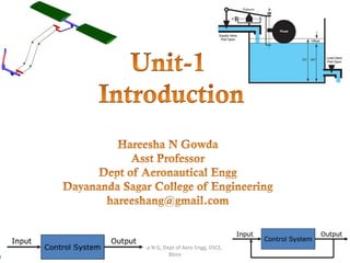
  • 1. 8/21/2017 1 Hareesha N G, Dept of Aero Engg, DSCE, Blore
  • 2. • Concept of automatic controls • Open loop and closed loop systems • Concepts of feedback systems • Requirements of an ideal control system • Types of controllers – Proportional, – Integral – Proportional Integral, – Proportional Integral Differential controllers 07 Hrs 8/21/2017 Hareesha N G, Dept of Aero Engg, DSCE, Blore 2
  • 3. 8/21/2017 The contents used in this presentation are taken from the text books mentioned in the references. I do not hold any copyrights for the contents. It has been prepared to use in the class lectures, not for commercial purpose. Hareesha NG Hareesha N G, Dept of Aero Engg, DSCE, Blore 3
  • 4. • Automatic control has played a vital role in the advance of engineering and science. • It is more important in space-vehicle systems, missile-guidance systems, robotic systems, modern manufacturing and industrial processes. • For example, – Numerical control of machine tools in the manufacturing industries. – Design of autopilot systems in the aerospace industries – Design of cars and trucks in the automobile industries. – Speed Governors 8/21/2017 Hareesha N G, Dept of Aero Engg, DSCE, Blore 4
  • 5. • It is also essential in industrial operations as – controlling pressure, – temperature, – humidity, – viscosity, and – flow in the process industries. • Automatic control helps in attaining optimal performance of dynamic systems, improving productivity, relieving the drudgery of many routine repetitive manual operations. 8/21/2017 Hareesha N G, Dept of Aero Engg, DSCE, Blore 5
  • 6. 8/21/2017 Hareesha N G, Dept of Aero Engg, DSCE, Blore 6 Automatic water lever controller Automatic Engine speed controller
  • 7. • An automatic control system is a pre-set closed-loop control system that requires no operator (human) action. • Automatic control uses application of mechanisms to the operation and regulation of processes without continuous direct human intervention. • This assumes the process remains in the normal range for the control system. • An automatic control system has two process variables associated with it: – a controlled variable – a manipulated variable. • A controlled variable is the process variable that is maintained at a specified value or within a specified range. • In the previous example, the storage tank level is the controlled variable. 8/21/2017 Hareesha N G, Dept of Aero Engg, DSCE, Blore 7
  • 8. • A manipulated variable is the process variable that is acted on by the control system to maintain the controlled variable at the specified value or within the specified range. • The flow rate of the water supplied to the tank is the manipulated variable. Functions of Automatic Control • In any automatic control system, the four basic functions that occur are: – Measurement – Comparison – Computation – Correction 8/21/2017 Hareesha N G, Dept of Aero Engg, DSCE, Blore 8
  • 9. System : A system is a combination or an arrangement of different physical components which act together as a entire unit to achieve certain objective. • E.g., – A classroom is a physical system. A room along with the combination of benches, blackboard, fans, lighting arrangement etc. can be called as a classroom which acts as elementary system. – In a classroom, professor is delivering his lecture, it becomes a control system as; he tries to regulate, direct or command the students in order to achieve the objective which is to input good knowledge to the students. 8/21/2017 Hareesha N G, Dept of Aero Engg, DSCE, Blore 9
  • 10. Plant : – The portion of a system which is to be controlled or regulated is called as the plant. – A plant may be a piece of equipment, perhaps just a set of machine parts. – The purpose of plant is to perform a particular operation. – E.g., mechanical device, a heating furnace, a chemical reactor, or a spacecraft. Process: – Any operation to be controlled is called a process. – Examples are chemical, economic, and biological processes. 8/21/2017 Hareesha N G, Dept of Aero Engg, DSCE, Blore 10
  • 11. Controller : – The element of the system itself or external to the system which controls the plant or the process is called as controller. – E.g., ON/OFF switch to control bulb. 8/21/2017 Hareesha N G, Dept of Aero Engg, DSCE, Blore 11
  • 12. Input : – It is an applied signal or an excitation signal applied to control system from an external energy source in order to produce a specified output. – For each system, there must be excitation and system accepts it as an input Output : – It is the particular signal of interest or the actual response obtained from a control system when input is applied to it. – for analysing the behaviour of system for such input, it is necessary to define the output of a system. 8/21/2017 Hareesha N G, Dept of Aero Engg, DSCE, Blore 12
  • 13. Disturbances : – Disturbance is a signal which tends to adversely affect the value of the output of a system. – Disturbances are undesirable and unavoidable effects beyond our control, generated from outside process-environment, and from within. – If such a disturbance is generated within the system itself, it is called as internal disturbance. – The disturbance generated outside the system acting as an extra input to the system in addition to its normal input, affecting the output adversely is called as an external disturbance. – The presence of the disturbance is one of the main reasons of using control. 8/21/2017 Hareesha N G, Dept of Aero Engg, DSCE, Blore 13
  • 14. 1) Natural Control System — Universe — Human Body 2) Manmade Control System — Vehicles — Aeroplanes 3) Manual Control Systems – Room Temperature regulation Via Electric Fan – Water Level Control 4) Automatic Control System – Room Temperature regulation Via A.C – Human Body Temperature Control 8/21/2017 Hareesha N G, Dept of Aero Engg, DSCE, Blore 14
  • 15. 5) Open-Loop Control System – Washing Machine – Toaster – Electric Fan 6) Closed-loop Control System – Refrigerator – Auto-pilot system – Driverless cars 7) Linear Vs Nonlinear Control System 8/21/2017 Hareesha N G, Dept of Aero Engg, DSCE, Blore 15 A Control System in which output varies linearly with the input is called a linear control system.
  • 16. 8) Time invariant vs Time variant – When the characteristics of the system do not depend upon time itself then the system is said to time invariant control system. – Time varying control system is a system in which one or more parameters vary with time. 9) Continuous Data Vs Discrete Data System – In continuous data control system all system variables are function of a continuous time t. – A discrete time control system involves one or more variables that are known only at discrete time intervals. 10) Deterministic vs Stochastic Control System – A control System is deterministic if the response to input is predictable and repeatable. – If not, the control system is a stochastic control system. 8/21/2017 Hareesha N G, Dept of Aero Engg, DSCE, Blore 16
  • 17. 8/21/2017 Hareesha N G, Dept of Aero Engg, DSCE, Blore 17
  • 18. • Any physical system which does not automatically correct for variation in its output, is called an open-loop system. • Such a system may be represented by the block diagram as shown in Fig. • In these systems, output is dependent on input but controlling action or input is totally independent of the output or changes in output of the system. • In these systems the output remains constant for a constant input signal provided the external conditions remain unaltered. 8/21/2017 Hareesha N G, Dept of Aero Engg, DSCE, Blore 18
  • 19. • In any open-loop control system the output is not compared with the reference input. As a result, the accuracy of the system depends on calibration. • In the presence of disturbances, an open-loop control system will not perform the desired task. Open-loop control can be used, in practice, only if the relationship between the input and output is known and if there are neither internal nor external disturbances. • Clearly, such systems are not feedback control systems. Note that any control system that operates on a time basis is open loop. • For instance, traffic control by means of signals operated on a time basis is an example of open-loop control. 8/21/2017 Hareesha N G, Dept of Aero Engg, DSCE, Blore 19
  • 20. Advantages: The advantages of open loop control system are, 1) Such systems are simple in construction. 2) Very much convenient when output is difficult to measure. 3) Such systems are easy from maintenance point of view. 4) Generally these are not troubled with the problems of stability. 5) Such systems are simple to design and hence economical. Disadvantages: The disadvantages of open loop control system are, 1. These systems are inaccurate and unreliable because accuracy of such systems are totally dependent on the accurate pre-calibration of the controller. 2. These systems give inaccurate results if there are variations in the external environment. 3. These systems cant sense internal disturbances in the system, after the controller stage. 4. Recalibration of the controller is necessary, time to time to maintain the quality and accuracy of the desired output. 8/21/2017 Hareesha N G, Dept of Aero Engg, DSCE, Blore 20
  • 21. 1) Automatic Toaster System • In this system, the quality of toast depends upon the time for which the toast is heated. • Depending on the time setting, bread is simply heated in this system. • The toast quality is to be judged by the user and has no effect on the inputs. 8/21/2017 Hareesha N G, Dept of Aero Engg, DSCE, Blore 21
  • 22. 2) Traffic Light Controller • A traffic flow control system used on roads is time dependent. • The traffic on the road becomes mobile or stationary depending on the duration and sequence of lamp glow. • The sequence and duration are controlled by relays which are predetermined and not dependent on the rush on the road. 8/21/2017 Hareesha N G, Dept of Aero Engg, DSCE, Blore 22
  • 23. 3) Residential Heating System • The indoor temperature is the response variable of interest, and it is affected by the main disturbance input—the outdoor temperature. • The desired temperature is set on a calibrated dial. This positions the valve that admits the steam for circulation through the radiator. • The valve dial is calibrated when the environment temperature has certain value. • When this value changes significantly, the controlled temperature will deviate from the desired value by a large error and hence precise control will not be realized. 8/21/2017 Hareesha N G, Dept of Aero Engg, DSCE, Blore 23
  • 24. Feedback Control Systems. • A system that maintains a prescribed relationship between the output and the reference input by comparing them and using the difference as a means of control is called a feedback control system. Closed-Loop Control Systems. • Feedback control systems are often referred to as closed-loop control systems. • In practice, the terms feedback control and closed-loop control are used interchangeably. • In a closed-loop control system the actuating error signal (which is the difference between the input signal and the feedback signal) is fed to the controller so as to reduce the error and bring the output of the system to a desired value. • The term closed-loop control always implies the use of feedback control action in order to reduce system error. 8/21/2017 Hareesha N G, Dept of Aero Engg, DSCE, Blore 24
  • 25. The various signals are, r(t) = Reference input e(t) = Error signal c(t) = Controlled output m(t) = Manipulated signal b(t) = Feedback signal 8/21/2017 Hareesha N G, Dept of Aero Engg, DSCE, Blore 25
  • 26. • The part of output, which is to be decided by feedback element is fed back to the reference input. The signal which is output of feedback element is called feedback signal, b(t). • It is then compared with the reference input giving error signal e(t) = r(t) ± b(t) • When feedback sign is positive, systems are called positive feedback systems and if it is negative systems are called negative feedback systems. • This error signal is then modified by controller and decides the proportional manipulated signal for the process to be controlled. • This manipulation is such that error will approach zero. This signal then actuates the actual system and produces an output. As output is controlled one, hence called controlled output c(t). 8/21/2017 Hareesha N G, Dept of Aero Engg, DSCE, Blore 26
  • 27. Advantages 1. Accuracy of these systems is always very high because controller modifies and manipulates the actuating signal such that error in the system will be zero. 2. closed loop system senses environmental changes, as well as internal disturbances and accordingly modifies the error. 3. There is reduced effect of nonlinearities and distortions. 4. Bandwidth (operating frequency zone) for such system is veryhigh. Disadvantages 1. systems are complicated and time consuming from design point of view and hence costlier. 2. Due to feedback, system tries to correct the error from time to time. Tendency to overcorrect the error may cause oscillations without bound in the system. 3. System has to be designed taking into consideration problems of instability due to feedback. 4. The stability problems are severe and must be taken care of while designing the system. 8/21/2017 Hareesha N G, Dept of Aero Engg, DSCE, Blore 27
  • 28. 1. Human Being • The best example is human being. If a person wants to reach for a book on the table, Position of the book is given as the reference. • Feedback signal from eyes, compares the actual position of hands with reference position. Error signal is given to brain. • Brain manipulates this error and gives signal to the hands. This process continues till the position of the hands get achieved appropriately. 8/21/2017 Hareesha N G, Dept of Aero Engg, DSCE, Blore 28
  • 29. 2. Home Heating System • In this system, the heating system is operated by a valve. • The actual temperature is sensed by a thermal sensor and compared with the desired temperature. • The difference between the two, actuates the valve mechanism to change the temperature as per the requirement. 8/21/2017 Hareesha N G, Dept of Aero Engg, DSCE, Blore 29
  • 30. 3. Manual Speed Control System • A locomotive operator driving a train is a good example of a manual speed control system. • The objective is to maintain the speed equal to the speed limits set. • The entire system is shown in the block diagram in the Fig. 8/21/2017 Hareesha N G, Dept of Aero Engg, DSCE, Blore 30
  • 31. 8/21/2017 Hareesha N G, Dept of Aero Engg, DSCE, Blore 31 Open Loop Closed Loop Any change in output has no effect on the input i.e. feedback does not exists. Changes in output, affects the input which is possible by use of feedback. Output measurement is not required for operation of system. Output measurement is necessary. Feedback element is absent. Feedback element is present. Error detector is absent. Error detector is necessary. It is inaccurate and unreliable. Highly accurate and reliable. Highly sensitive to the disturbances. Less sensitive to the disturbances. Highly sensitive to the environmental changes. Less sensitive to the environmental changes. Bandwidth is small. Bandwidth is large. Simple to construct and cheap. Complicated to design and hence costly. Generally are stable in nature. Stability is the major consideration while designing Highly affected by nonlinearities. Reduced effect of nonlinearities.
  • 32. To achieve the required objective, a good control system must satisfy the following requirements. 1. Accuracy : – A good control system must be highly accurate. – The open loop systems are generally less accurate and hence feedback is introduced to reduce the error in the system. 2. Sensitivity : – A good control system should be very insensitive to environmental changes, age etc. But, must be sensitive to the input commands. – The performance should not be affected by small changes in the certain parameters of the system. 8/21/2017 Hareesha N G, Dept of Aero Engg, DSCE, Blore 32
  • 33. 3) External disturbance or noise : – All the physical systems are subjected to external disturbances and noise signals during operation. – A requirement of a good control system is that system is insensitive to noise and external disturbances but sensitive to the input commands. – It should be able to reduce the effects of undesirable disturbances. 4) Stability : – A concept of stability means output of system must follow reference input and must produced bounded output for bounded input. – A good control system is one which is stable in nature. 8/21/2017 Hareesha N G, Dept of Aero Engg, DSCE, Blore 33
  • 34. 5) Bandwidth : – This requirement is related to the frequency response of the system. – For the input frequency range, it should give satisfactory output. 6) Speed : – A system should have good speed. This means output of the system should approach to its desired value as quickly as possible. – System should settled down to its final, value as quickly as possible. 7) Oscillations : – The system should exhibits suitable damping i.e. the controlled output should follow the changes in the reference input without unduly large oscillations or overshoots. 8/21/2017 Hareesha N G, Dept of Aero Engg, DSCE, Blore 34
  • 35. • The concept of a control system is to sense deviation of the output from the desired value and correct it, till the desired output is achieved. • The deviation of the actual output from its desired value is called an error. The measurement of error is possible because of feedback. • The feedback allows us to compare the actual output with its desired value to generate the error. • The controller is an element which accepts the error in some form and decides the proper corrective action. • The output of the controller is then applied to the process or final control element. This brings the output back to its desired set point value. • The controller is the heart of a control system. The accuracy of the entire system depends on how sensitive is the controller to the error detected and how it is manipulating such an error. 8/21/2017 Hareesha N G, Dept of Aero Engg, DSCE, Blore 35
  • 36. Most industrial controllers may be classified according to their control actions as: 1. Two-position or on-off controllers 2. Proportional controllers 3. Integral controllers 4. Proportional-plus-integral controllers 5. Proportional-plus-derivative controllers 6. Proportional-plus-integral-plus-derivative controllers 8/21/2017 Hareesha N G, Dept of Aero Engg, DSCE, Blore 36
  • 37. • The most elementary controller mode is the two-position or ON/OFF controller mode. • It is the simplest, cheapest. • The most general form can be given by: P = 0 % ep < 0 P = 100 % ep > 0 • The relation shows that when the measured value is less than the set-point (i.e. ep > 0), the controller output will be full (i.e. 100%), • when the measured value is more than the setpoint (i.e. ep < 0), the controller output will be zero (i.e. 0%). 8/21/2017 Hareesha N G, Dept of Aero Engg, DSCE, Blore 37 Ex. ON/OFF switch
  • 38. 8/21/2017 • In this control mode, the output of the controller is simple proportional to the error e(t). • The relation between the error e(t) and the controller output p is determined by constant called proportional gain constant denoted as Kp. • The output of the controller is a linear function of the error e(t). • Thus each value of the error has a unique value of the controller output. • The range of the error which covers 0 % to 100 % controller output is called proportional band. • The basic relationship between output of the controller and error signal is given by, p(t) = Kp e(t) Taking Laplace transform, P(s) = Kp E(s) Hareesha N G, Dept of Aero Engg, DSCE, Blore 38 Kp = Proportional gain constant
  • 39. 8/21/2017 • Though there exists linear relation between controller output and the error, for a zero error the controller output should not be zero, otherwise the process will come to halt. • Hence there exists some controller output Po for the zero error. Hence mathematically the proportional control mode is expressed as, p(t) = Kp e(t) + Po Hareesha N G, Dept of Aero Engg, DSCE, Blore 39 Kp = Proportional gain constant Po = Controller output with zero error
  • 40. 8/21/2017 • In the proportional control mode, error reduces but can not go to zero. • It finally produces an offset error. It can not adapt with the changing load conditions. To avoid this, another control mode is often used in the control systems which is based on the history of the errors. This mode is called integral mode or reset action controller. • In such a controller, the value of the controller output p(t) is changed at a rate which is proportioned to the actuating error signal e(t). Mathematically it is expressed as, Taking Laplace transform, sP(s) = Ki E(s) or P(s) = (Ki/s) E(s) Hareesha N G, Dept of Aero Engg, DSCE, Blore 40    teK dt tdp i Ki = Constant relating error and rate
  • 41. 8/21/2017 • The constant Ki is also called integral constant. • Integrating the above equation, actual controller output at any time t can be obtained as, Where p(0) = Controller output when integral action starts i.e. at t = 0. Hareesha N G, Dept of Aero Engg, DSCE, Blore 41      0 0 pdtteKtp t i  
  • 42. 8/21/2017 • The controller produces a control action that is proportional to the rate at which the error is changing de(t)/dt. • The mathematical equation for the mode is, where Kd = Derivative gain constant. Taking Laplace transform P(s) = Kd s E(s) Hareesha N G, Dept of Aero Engg, DSCE, Blore 42     dt tde Ktp d
  • 43. 8/21/2017 • This is a composite control mode obtained by combining the proportional mode and the integral mode. • The mathematical expression for such a composite control is, Taking Laplace transform, Hareesha N G, Dept of Aero Engg, DSCE, Blore 43        0 0 pdtteKKteKtp t ipp      sE s KK KsP ip p           sE s K KsP i p      1
  • 44. 8/21/2017 • The series combination of proportional and derivative control modes gives proportional plus derivative control mode. • The mathematical expression for the PD composite control is, • Taking Laplace transform, • The addition of a derivative mode to a proportional controller modifies its response to inputs. • A PD controller provides an element to the response which is largest when the rate of change of the error is greatest and diminishes as it becomes smaller. • The derivative mode is never used alone because it is not capable of maintaining a control signal under steady error conditions. • It is always used with the proportional mode and often additionally with the integral mode.Hareesha N G, Dept of Aero Engg, DSCE, Blore 44        0p dt tde KKteKtp dpp       sEsKKKsP dpp 
  • 45. 8/21/2017 • The composite controller including the combination of the proportional, integral and derivative control mode is called PID control mode and the controller is called three mode controller. • It is very much complex to design but very powerful in action. • Mathematically such a control mode can be expressed as, Hareesha N G, Dept of Aero Engg, DSCE, Blore 45          0 0 p dt tde KKdtteKKteKtp dp t ipp      sEsKK s KK KsP dp ip p             sEKsKs s K sP id p  2
  • 46. 8/21/2017 • This mode has advantages of all the modes. • The integral mode eliminates the offset error of the proportional mode and the response is also very fast due to derivative mode. • The sudden response is produced due to derivative mode. • Thus it can be used for any process condition. • With the PID control action, there is no offset, no oscillations with least settling time. • So there is improvement in both transient as well as steady state response. Hareesha N G, Dept of Aero Engg, DSCE, Blore 46
  • 47. 8/21/2017 A The Fulcrum can be adjusted horizontally by turning knob A B The Float can be adjusted vertically by turning knob B Hareesha N G, Dept of Aero Engg, DSCE, Blore 47 Desired Value (DV ) = The required level of water in the tank Measured Value (MV) = The actual level of water in the tank. Offset or Error (E) = The difference between the required and actual level (DV-MV) Gain (K) = The ratio of float movement to valve movement • The water level and the Float continue to drop and the Supply Valve continues to open until the water flow into the tank equals the flow out of the tank at which point the water level stops falling. • The system has now reached steady state but the tank level is now lower than the required level (DV>MV) and there is an Offset. • In a Proportional only system under load there will always be an Offset and that offset will vary dependant on the size of the load. Courtesy: http://aeroquad.com
  • 48. 8/21/2017 • Proportional control will always result in an Offset between Measured Value and Desired Value and for every load there will be a different steady state water level. • As the Gain increases the Offset decreases. • As the Gain increases the stability decreases until the system becomes unstable. • With Proportional only control a compromise must be reached between size of Offset and stability by adjusting the Gain. • In some systems an Offset is acceptable, as in the water tank described above, and Proportional only control is acceptable. • However in other systems an offset of any size is unacceptable and some other form of control is required. Hareesha N G, Dept of Aero Engg, DSCE, Blore 48
  • 49. 8/21/2017 • With the system we described above, under load, assuming the Gain of system has been adjusted to its optimum value, the water level will settle with an Offset from the Desired Value. • By adjusting knob B so that the float moves upwards, relative to the water level, the Supply Valve will open more, the flow in will increase and the Offset will reduce. • Eventually a new height of the Float will be found where the flow into the tank equals the flow out , the Measured value equals the Desired Value and Offset will be zero. Hareesha N G, Dept of Aero Engg, DSCE, Blore 49Courtesy: http://aeroquad.com
  • 50. 8/21/2017 • The speed at which the Float height is adjusted can be fast or slow. • If it is too fast the system can become unstable (hunting) and if it is too slow time will be wasted. • With Integral control the speed at which Offset is removed is made directly proportional to the size of the Offset. • In the water tank system, we could achieve this by operating knob B with a variable speed servo motor. • The amount of integral action applied would be controlled by adjusting the ratio between Motor speed and size of Offset. Hareesha N G, Dept of Aero Engg, DSCE, Blore 50Courtesy: http://aeroquad.com
  • 51. 8/21/2017 • Not all systems can be controlled by Proportional and Integral control only. • In the water tank system, an increase in load results in an immediate drop in water level and the Float. • The Supply Valve is immediately opened allowing water into the tank. • In some systems there is a delay or lag in response to a change in load. • For example, a wind tunnel has a large heavy fan. If more power is applied to increase the fan's speed there will be a significant delay before the new speed is achieved due to the time needed to overcome the inertia of the fan. • To overcome the inertia more power (than actually required) is required to maintain the desired speed (DV), to accelerate the fans speed change. Hareesha N G, Dept of Aero Engg, DSCE, Blore 51
  • 52. 8/21/2017 • The additional power is then reduced to the level required to maintain the required speed. • In the water tank system, under Proportional and Integral control, knob B is operated by a variable speed servo motor. • If there was inertia in the system, due to friction in the linkage between the Float and the Supply Valve, Derivative action would temporarily apply a higher speed to the servo motor than was necessary to remove the Offset. Hareesha N G, Dept of Aero Engg, DSCE, Blore 52 Summary: 1. Derivative action speeds up the removal of the Offset. 2. It is required in systems which have large time delays due to Inertia or large capacities. 3. It tends to make a system more stable as it is increased it can cause hunting and instability
  • 53. 8/21/2017 Proportional action (P) Arrests It arrest the change of the Measured Value but always with an Offset from the Measured Value Integral action (I) Restores It removes the Offset ​ Derivative action (D) Accelerates It speeds up the removal of the Offset Hareesha N G, Dept of Aero Engg, DSCE, Blore 53
  • 54. 8/21/2017 1. Modern Control Engineering, Katsuhiko Ogatta, Pearson Education,2004. 2. Control System Engineering, U.A.Bakshi 3. Control Systems, W. Bolton, Elsevier Ltd. 4. http://aeroquad.com/showwiki.php?title=A-Guide-To-Proportional- Integral-and-Derivative-PID-Control Hareesha N G, Dept of Aero Engg, DSCE, Blore 54
  • 55. 8/21/2017 The contents used in this presentation are taken from the text books mentioned in the references. I do not hold any copyrights for the contents. It has been prepared to use in the class lectures, not for commercial purpose. Hareesha NG Hareesha N G, Dept of Aero Engg, DSCE, Blore 55
  • 56. Please to me if you have any suggestions/criticisms. hareeshang@gmail.com 8/21/2017 Hareesha N G, Dept of Aero Engg, DSCE, Blore 56