Birefringent coatings
•
24 likes•16,557 views

This presentation gives the information about: Birefringent coatings, covering syllabus of Unit-6, Sub: Experimental stress analysis for BE course.

Recommended
More Related Content
What's hot
What's hot (20)
Similar to Birefringent coatings
Similar to Birefringent coatings (20)
More from Hareesha N Gowda, Dayananda Sagar College of Engg, Bangalore
More from Hareesha N Gowda, Dayananda Sagar College of Engg, Bangalore (20)
Recently uploaded
Recently uploaded (20)
Birefringent coatings
- 1. 4/4/2014 Hareesha N G, Asst Prof, DSCE, Blore 1
- 2. UNIT-6: Photo-elastic (Bire-fringent) Coatings : • Birefringence coating stresses • Effects of coating thickness – Reinforcing effects, Poisson’s ratio mismatch • Stress separation techniques – Oblique incidence, Strip coatings 08 Hours 4/4/2014 2Hareesha N G, Asst Prof, DSCE, Blore
- 3. INTRODUCTION • In the application of coating methods, one applies a thin layer of a reactive material to the surface of the body that is to be analyzed. • The thin coating is bonded to the surface and displacements at the coating-specimen interface are transmitted without amplification or attenuation. • These displacements at the interface produce stresses and strains in the coating and the coating responds. • The analyst observes the coating response and infers the stresses on the surface of the specimen based on the observed behavior of the coating. 4/4/2014 3Hareesha N G, Asst Prof, DSCE, Blore
- 4. ADVANTAGES OF COATING METHODS • The capability of applying the coating directly to the prototype: • The "whole"-field response of the coating: Stain gages respond over small regions of the field and give approximations to strain at a point. Coatings respond over the entire surface of the specimen and give field data rather than point data. • There are two coating methods that are used in stress analysis. – Bire-fringent coating that produces a photo-elastic fringe pattern related to the coating stresses. – Brittle coating that fails by cracking when the coating stresses exceed some threshold value. 4/4/2014 4Hareesha N G, Asst Prof, DSCE, Blore
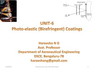
- 5. BIREFRINGENT COATINGS • The method of birefringent coatings represents an extension of the procedures of photoelasticity to the determination of surface strains in opaque two- and three-dimensional bodies. • The coating is a thin sheet of birefringent material, usually a polymer, which is bonded to the surface of the prototype being analyzed. • The coating is mirrored at the interface to provide a reflecting surface for the light-When the prototype is loaded, the displacements on its surface are transmitted to the mirrored side of the coating to produce a strain field through the thickness of the coating. • The distribution of the strain field over the surface of the prototype, in terms of principal-strain differences, is determined by employing a reflected-light polariscope to record the fringe orders, as illustrated in Fig. 4/4/2014 5Hareesha N G, Asst Prof, DSCE, Blore (Contd…..)
- 6. 4/4/2014 6Hareesha N G, Asst Prof, DSCE, Blore Reflection polari-scopes commonly used in photoelastic- coating measurements: P-polarizer; A-analyzer; λ/4, quarter-wave plate.
- 7. BIREFRINGENT COATINGS (…..Contd) • The birefringent-coating method has many advantages over other methods of experimental stress analysis. • It provides full-field data that enable the investigator to visualize the complete distribution of surface strains. • The method is nondestructive, and since the coatings can be applied directly to the prototype, the need for models is eliminated. • Through proper selection of coating materials, the method can be made applicable over a very wide range of strain. 4/4/2014 7Hareesha N G, Asst Prof, DSCE, Blore
- 8. Photo stress coating being contoured to the surface of a vehicle water pump casting 4/4/2014 Hareesha N G, Asst Prof, DSCE, Blore 8
- 9. Commercial Reflection Polariscope 4/4/2014 Hareesha N G, Asst Prof, DSCE, Blore 9
- 10. 4/4/2014 Hareesha N G, Asst Prof, DSCE, Blore 10
- 11. Photo Stress pattern revealed on a mechanical controlled linkage system in a passenger Air craft 4/4/2014 Hareesha N G, Asst Prof, DSCE, Blore 11
- 12. P. S. Testing under progress on a main landing gear of Airbus A 330/A340 passenger air craft 4/4/2014 Hareesha N G, Asst Prof, DSCE, Blore 12
- 13. 4/4/2014 Hareesha N G, Asst Prof, DSCE, Blore 13
- 14. Photo stress fringe pattern at a specific area of an Airbus gear during a static test sequence 4/4/2014 Hareesha N G, Asst Prof, DSCE, Blore 14
- 15. Final prototyping test on a landing gear from a military fighter jet aircraft and P. S. fringe pattern at several sections of the Landing gear 4/4/2014 Hareesha N G, Asst Prof, DSCE, Blore 15
- 16. Photo Stress fringe pattern on a partially coated prototype of Boeing 767 main landing gear 4/4/2014 Hareesha N G, Asst Prof, DSCE, Blore 16
- 17. Coated area on Jet engine Frames Strain pattern at a specific location of fuel pads and struts 4/4/2014 Hareesha N G, Asst Prof, DSCE, Blore 17
- 18. Properties which an ideal coating should exhibit 1. A high optical strain coefficient K to maximize coating response 2. A low modulus of elasticity Ec to minimize reinforcing effects 3. A high resistance to both optical and mechanical stress relaxation to ensure stability of the measurement with time 4. A linear strain-optical response to minimize data-reduction problems 5. A good adhesive bond to ensure perfect strain transmission between coating and specimen 6. A high proportional limit to increase the range of strain over which the coating can be utilized 7. Sufficient malleability to permit use on curved surfaces of three- dimensional components 4/4/2014 18Hareesha N G, Asst Prof, DSCE, Blore
- 19. 4/4/2014 Hareesha N G, Asst Prof, DSCE, Blore 19
- 20. COATING STRESSES • Refer class notes 4/4/2014 20Hareesha N G, Asst Prof, DSCE, Blore
- 21. EFFECTS OF COATING THICKNESS • When a photoelastic coating is bonded to a specimen, only in a few instances are the strains transmitted to the coating without some modification or distortion. • More realistically, the coating is considered as a three-dimensional extension of the specimen which is loaded by means of shear and normal tractions at the interface. • These tractions vary so that the displacements experienced by the coating and the specimen at the interface are identical (as dictated by perfect bonding). • Thus, in the most general case: – The average strain in the coating does not equal the strain at the interface. – A strain gradient exists through the thickness of the coating. – The coating serves to reinforce the specimen. • It is evident that these effects of thickness tend to vanish as the coating thickness approaches zero. • However, coatings with finite thickness (usually 0.50 to 3.00 mm, or 0.02 to 0.10 in) are required to obtain a high fringe count for accurate fringe- order determinations. 4/4/2014 21Hareesha N G, Asst Prof, DSCE, Blore Traction refers to the maximum frictional force that can be produced between surfaces without slipping