
Recommandé
Recommandé
Contenu connexe
Tendances
Tendances (20)
Similaire à Long Endurance VTOL UAV Design & Dual-Use Commercialization
Similaire à Long Endurance VTOL UAV Design & Dual-Use Commercialization (20)
Dernier
Dernier (20)
Long Endurance VTOL UAV Design & Dual-Use Commercialization
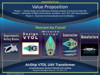
- 1. AirShip Technologies Group 1 Value Proposition Phase 1 – Vehicle design and preliminary prototype analysis of endurance trade-offs Phase 2 – Verification of flight control (theory, simulation, and VTOL UAV demonstration) AirShip VTOL UAV Transformer Long Endurance Vertical Takeoff and Landing Benjamin.Berry@comcast.net 503 320-1175 www.AirShipTG.org Reinvent the Future! Phase 3 – Dual-Use Commercialization and Certification
- 2. AirShip Wins Linus Pauling Award AirShip Technologies Group won the Win2011 Linus Pauling Innovative Company of the Year award with their entry of the AirShip VTOL UAV Transformer known as “AirShip Endurance V5.” Fellow innovators from around the Pacific NW region met at the Willamette Innovators Summit for an evening of networking and collaboration. Cutting-edge research, commercialization efforts from Oregon State University and exhibits from over 50 leading businesses were represented within the area. The event featured industry leading speakers and success stories from the region’s star entrepreneurs. Ben Berry, CEO of AirShip Technologies Group, demonstrated the prototype AirShip VTOL UAV. November 10, 2011
- 3. 16.0 60.0 Span (Inches) at Rest 60.0 108.0 Span (Inches) at Flight 8 Tip Chord (Inches (trap) 0.366 0.228 Taper Ratio (trap) 1.708 6.865 Aspect Ratio (gross) 207.4 1,128.0 Area (Sq. Inches) (gross) V-WING TAIL WING AIR/VEHICLE Critical Dimensions 16.0 60.0 Span (Inches) at Rest 60.0 108.0 Span (Inches) at Flight 8 Tip Chord (Inches (trap) 0.366 0.228 Taper Ratio (trap) 1.708 6.865 Aspect Ratio (gross) 207.4 1,128.0 Area (Sq. Inches) (gross) V-WING TAIL WING AIR/VEHICLE Critical Dimensions 108.0 76.3 39.5 108.0 38.0 24.0 30.0 47.0 18.0 24.0 “AirShip Endurance V9” Critical Dimensions Special Operations Transport - USAF Research Lab Submittal November 14, 2011
- 4. Team Members AirShip Technologies Group Ben Berry Innovation Program Leadership, Aerospace and Defense, and International Airport Operations, Government Transportation Industry Puneet Kukkal Engineering Management, Analysis and Planning, Business Strategy Benny Berry Aerospace and Defense, Aeronautical Engineering, Consulting and Prior Tuskegee Airman Military Pilot Gerald Baugh Economic Development, Business and Operations, and Current Pilot B _ ____ y P ___ l G__ ___ ___ Red Tails (2012) HD Movie Trailer
- 5. Priyanka Kukkal Defense Systems, Engineering and Operations, Government Industry, Isensepro, Inc. Mark Van Patten Engineering & Business Management, Human-to- Machine Interface Systems, Oregon State Univ. Mike EOM Operations & Technology Management, Computing & Engineering, University of Portland Yew-Seng Tan VTOL Aircraft Engineering, Technology Management ____________________ Team Members P l ___________________ y _ ______ y AirShip Technologies Group
- 6. AirShip Technologies Group 6 Functional Organization Chart • Privately owned • Board of Advisors advise CEO • Academic/ commercial partnerships • Air/vehicle design and manufacturing
- 7. AirShip Technologies Group 7 Skill Sets – Aeronautical design – Functional design – System analysis – System architecture – System construction – Technical writing – Project management Academic/Commercial Partnerships Academic Commercial • Operations & Technology Management • University Internships Team • Workflow Accountability • Business, Science and Engineering Programs
- 8. X-Hawk Yes Yes Wood propeller; fixed Modified ducted-fan AirShip Technologies Group 8 The Tactical Problem Major hurdles are faced by military ground troops: • Ground and air transportation remain effective but have separate modes of operation.. • Warfighter needs to avoid water, difficult terrain, road obstructions, improvised explosive devices (IEDs) and ambush threats. • Need air platform with high flight endurance and capable of driving on prepared surfaces, light off- road conditions or rough terrain, while pilotless flight functionality employs VTOL (vertical take off and landing) ability and cruising up to 10,000 feet above ground. • Small launch and land footprint. Lockheed Martin's Ducted-Fan Design Carter Aviation Technologies‘ AAI's Design Vertical Take Off & Land VTOL Production The Challenge: Build an Air-to-Ground VTOL UAV AirShip VTOL UAV Transformer Design Israel Air Force X-Hawk
- 9. AirShip Technologies Group 9 SBIR Air Platform Objective: Design and test a Tier 2 sized long-endurance VTOL UAV. Show how the design can be scaled and identify critical size/weight/endurance limits. Design control algorithms for all flight regimes. PHASE I: Vehicle design and preliminary analysis of endurance trade-offs. (9 months) Propose control strategy for hover and transition regimes. Determine implementation and demonstration plan. Initial demonstrations of key technologies and pre-prototype air/vehicle. PHASE II: Verification of flight control design performance (simulation/demos. (18 months) Final prototype air/vehicle built and flight tested with accompanying analysis of safety, noise level, robustness to disturbances, failure modes, scalability, and endurance tradeoffs. PHASE III: Dual Use Commercialization and FAA Certification. (12 months) Military and Commercial Dual Use Application: Work with marketplace to develop VTOL / UAV manufacturing capability for air/vehicles of record in markets for the military, homeland security, hazardous material monitoring, crop inspection, search, rescue, and commercial. Critical Dimensions
- 10. Mission Cycles without Refueling Cycle 1. Ship to Shore Insertion Manually drive 30 miles To unload site Fly 110 miles Fly 110 miles Vertical Take off Cycle 3. Special Operations Forces Resupply Load supplies At staging base Land back at staging base Land - Drive Drop off Vertical Land Fly 120 miles to shore Drive 130 miles Reserve 10 min Vertical Take off Depart ship based Staging area Land at area of operation Reserve 10 min Vertical Land Fly 60 miles Fly 60 miles Vertical Take Off Cycle 2. IED Avoidance Drive 30 miles Avoid IED Zone Scout or Patrol Reserve 10 min Vertical Take Off Vertical Land Drive 100 miles Drive 20 miles to Injured Soldier location Fly 120 miles Fly 110 miles Vertical Take off Cycle 4. Medical Evacuations Depart stage area in response to Emergency Call Land at medical facility Land - Drive Pickup - Recover Reserve 10 min AirShip Technologies Group
- 11. 11 Drone Diverse Market Requirements DARPA – US Army • AirShip Endurance V17 • 4 troops • Resupply • Medical Evacuation • 17 ft long by 16 ft span • 1,200 lbs. payload • Endurance: 5 hours USAF – Research Lab • AirShip Endurance V9 • Special Operations Transport • 2 troop transport • 9 ft long by 9 ft span • 1,000 lbs. payload • Endurance: 10 hours USAF – SBIR • AirShip Endurance V5 • Reconnaissance • Surveillance • 5 ft long by 3.5 ft span • 70 lbs. payload • Endurance: 72 hours Dual-Use • AirShip Endurance V2 • Reconnaissance • Surveillance • 25“ long by 17.5” span • 4.4 lbs. payload & total weight • Endurance: Persistent Surveillance
- 12. AirShip VTOL Transformer Delivers • Focus on innovation and technology development and manufacturing. • Integrates management of VTOL UAV design, construction, test and dual-use commercialization. • Partners with engineers and scientists in air/vehicle design and development. . • Forges academic/commercial partnerships aligned with University engineering and operations degree programs that create high-tech skills. • Enables future generation of family- wage jobs through the employment of people and technology. Internal Components View Aerial Components View AirShip Technologies Group
- 13. 13 AirShip Technologies Group Critical Dimensions 5.0 5.0 V17 V9
- 14. AirShip Technologies Group 14 • Ducted fan rotors are twin rotors that spin in opposite directions on a single post. The contra-rotating blades cancel out each other's torque effects so the AirShip doesn't need a tail rotor. This makes the aircraft easier and safer to fly at treetop height. Eliminating the need for a vertical tail rotor and an associated electric drive system reduces the vehicle's profile, while the pivot up rear rotor assembly provides forward thrust. • Agility. AirShip VTOL turns by changing the pitch angle of its lateral upper and lower rotor blades to different degrees. At a hover in mid-air, the more sharply pitched of the two rotors develops more lift and absorbs more power than its counterpart, creating a powerful, instant torque effect that snaps the fuselage around in the direction the UAV wants to go. lateral ducted fan rotor assemblies and a rear V-Wing horizontal stabilizer tail. The low- aspect ratio wings extend upon take-off. During ground transit, the AirShip Endurance V17 is 10 feet wide conforming to the demands of ground traffic and terrain. Slide forward and aft hydraulic doors AirShip VTOL/UAV Transformer Characteristics. During air transit, the vehicle is 17 feet long by 16 feet wide with approximately half of the width taken up by
- 15. AirShip Technologies Group 15 AirShip VTOL/UAV Transformer Flight Control and Flight Management • Designed as an unmanned aerial vehicle (UAV), AirShip Endurance is dispatch able for downed airman recovery, or evacuating injured personnel from difficult to access locations, or hovering surveillance. • An autopilot system flies the aircraft for effective AirShip unmanned operations. Using automated controls and flight-management systems, AirShip Endurance is suitable for operations in built-up areas that allow the aircraft to counteract inevitable human errors which make war zones so dangerous.
- 16. AirShip Technologies Group 16 Airframe and Drive Train • Similar to those found in race cars and fixed wing aircraft, the airframe weighs a scant 375 pounds and can support 3,200 pounds gross weight. • Critically developed electric in-motor ground wheels, brakes, suspension and steering systems are specified for adaptation to the chassis. • Exterior fuselage panels are made of composites. • Ground transit, electric in-motor wheels hold tires in place, vastly simplifying the all wheel drive and drive-by-wire system. • The wheel configuration and transit drive system enable the driver to maneuver all three or alternatively four wheel configuration for handling and steering. • For air transit, the ground wheels are partially retractable into the airframe. Airframe View AirShip VTOL/UAV Transformer
- 17. AirShip Technologies Group 17 Cutaway View Components • The backbone airframe and fuselage have a strong reinforced underbody that is ridged but light weight, while the upper body panels are assembled as independent components. The vehicle’s upper frame is designed as an integrated roll bar structure and acts as a pivot for the hydraulic slide forward/aft door configuration. • Four-seat cabin forward positioning allows for full views of instrumentation controls and changing canopy views during both air and ground transit. Mid- positioned passengers have a commanding view of front and lateral scenes through the front heads up canopy and door window views. • The cutaway view shows the aggregate assembly of the backbone frame, the titanium reinforced and composites underbody, and the upper frame. • Interior and exterior sub-components are installed in each of 4-piece assembly phases. AirShip VTOL/UAV Transformer
- 18. AirShip Technologies Group 18 Air and Ground Transit • AirShip VTOL’s design answers the search for a viable air/ground transport vehicle that combines the short hop virtuosity and speed of a helicopter with the convenience, economy and comfort of a high performance ground vehicle. This AirShip VTOL UAV air/vehicle is designed to compete and survive on the battlefield but also with other modes of road and cross-terrain transport. • AirShip’s 1,000 lbs payload cabin is an extremely stable and rigid cell, designed for maximum protection and fast deployment. Seen here is the undercarriage airframe of the payload cabin nestled around ducted rotor housing. AirShip VTOL/UAV Transformer
- 19. AirShip Technologies Group 19 Stationary View with Hydraulic Slide Door Extended • Doors extend at rest and add to stability of vertical lift transportation. Slide -forward doors were chosen partly for safety reasons as they are less prone to jam in a crash. • Doors open fully to expose the payload bay and allow for the most convenient entry and exit. AirShip VTOL/UAV Transformer Performance • Ground speed acceleration is specified at 65 miles/hour within 5 seconds while traveling via an in-motor wheel drive train. The vehicle redlines at 80 miles per hour while ground breaking to zero occurs from 60 miles per hour in 116 feet. • Air speed climbs to 300 nautical miles per hour through a straight line path while power is ported to six twin ducted rotor electric turbine fans. • From the lateral view, the AirShip is aerodynamic and hides the forward turbine assemblies while showing detail of the curved fuselage, rear V-Wing tail and canard supports. In-flight Extended Low-Aspect Ratio Wings Vertical Take-Off, Hover and Landing
- 20. AirShip Technologies Group 20 • Three turbine assemblies supporting twin counter rotating turbines on either side plus twin counter rotating turbines in the rear, help support this unique configuration while ensuring stability. Lift stability is maintained by the electric turbine fans during vertical operation when absence of horizontal airspeed would normally render control surfaces ineffective. • Ground transit wheels and wheel shields retract into the vehicle’s fuselage during air transit. Aerodynamics • Aerodynamics. The AirShip employs a wide aerodynamic frame, with twin canards retractable from the fuselage just forward of the cockpit, and side integrated low-aspect ratio retractable wings set mid-range to rear on the aircraft’s mid-section. • A top rear wing serves as an angled V-Wing tail section where two in-set winglets rise to a 45-degree position. Together, the two tail winglets serve as stabilizers in flight and recline at ground transit. AirShip VTOL/UAV Transformer
- 21. AirShip Technologies Group 21 Multibladed Rotor Turbines • AirShip’s rotors are multibladed turbines set inside a coaxial duct or cowling, also called a ducted propeller or a shrouded propeller, although in a shrouded propeller the ring is usually attached to the propeller tips and rotates. • The duct serves to protect the blades from adjacent objects and to protect objects from the revolving blades, but more importantly, the duct prevents radial air flow leakage at the blade tips thus maximizing thrust. AirShip VTOL/UAV Transformer
- 22. * For AirShip’s lateral ducted turbines, changing the pitch angle of its upper and lower rotor blades to different degrees controls yaw during hover. The more sharply pitched of the two rotors develops more lift and absorbs more power than its counterpart, creating a powerful, immediate instant torque effect that snaps the fuselage around in the direction specified. AERILONS CONTROL ROLL RUDERS CONTROL YAW CANARDS, ELEVATORS & EMPENNAGE V-WING CONTROL PITCH REAR TURBINE CONTROLS PITCH PITCH ANGLE OF LATERAL UPPER & LOWER BLADES CONTROL YAW* PITCH ANGLE OF ONE LATERAL TURBINE’S UPPER & LOWER BLADES CONTROL ROLL AirShip Fixed Wing Flight Control AirShip Hover Flight Control *
- 23. AirShipVTOL UAV Drone with Electric Persistent Endurance V2 and V5 AirShip Technologies Group Turbo Shaft to Turbine Gear Drive Exhaust Compression Anterior View 3-to-4 wheel, Air-to- Ground Transit Transformer 5 - 30 Hp Turbo Shaft Engines (2) 10 - 200 lbs Thrust Front View Composite Frame Clear Space Master Electric Power Generator Lithium-ion Battery Rechargeable Fuel Packs (4) Electric In-Motor Wheel Drivetrain and Power Generator Assemblies for Ground Transit and Electric Propeller Power Top Mid Air Intakes Power Circuit Unit PCU (Controller for Electric Wheel Generators, Electric Engines & Master Generator) Lateral Tri- Fan Turbine Assembly (2) Electricity Synchronous Rotor Drive Horizontal to Vertical 10 to 200 lbs Quiet Air Thrust Lateral View Manual Fold and Store Low Aspect Wings Solar Array Fabric
- 24. AirShipVTOL UAV Drone Transformer with Hybrid Electric Air Accelerator V9 and V17 AirShip Technologies Group Turbo Shaft to Turbine Gear Drive Exhaust Compression Anterior View 3-to-4 wheel, Air-to- Ground Transit Transformer 1,250 Hp Turbo Shaft Engines (2) 6,000 lbs Thrust Front View Titanium Frame Ceramic Tile Panel Ballistics Protection Liquid Fuel Tank Clear Space Master Electric Power Generator Lithium-ion Battery Rechargeable Fuel Packs (4) Electric In-Motor Wheel Drivetrain and Power Generator Assemblies for Ground Transit and Electric Propeller Power Top Mid Air Intakes Power Circuit Unit PCU (Controller for Electric Wheel Generators, Electric Impeller & Master Generator) Lateral Tri- Fan Turbine Assembly (2) Electricity Fuel Synchronous Rotor Drive Horizontal to Vertical 6,000 lbs Quiet Air Thrust Lateral View Fold and Store Low Aspect Wings
- 25. AirShip Technologies Group 25 Dual Turbo Shaft Engines • The MTU Turbomeca Rolls-Royce MTR390 is a turbo shaft developed for light helicopter applications; provides variable speed capabilities and low fuel consumption. • Two engines installed near the front fuselage exterior with air scoop cooling. AirShip VTOL/UAV Transformer General characteristics Type: Centrifugal Turboshaft Length: 42.4 in (108 cm) Diameter: 26.8 in (68 cm) Dry weight: 372 lb (169 kg) Components Compressor: Centrifugal, 2 stage Combustors: Annular Turbine: 1 stage high pressure turbine, 2 stage low pressure turbine Performance Maximum power output: 1465 shp Overall pressure ratio: 13:1 Specific fuel consumption: 0.46 lb/shp-hr Power-to-weight ratio:
- 26. AirShip Technologies Group 26 Dual Turbo Shaft Engines (TSE) AirShip VTOL/UAV Transformer • An electric start configuration links the TSE and electric motors to bifurcated rotor drive shafts. • Avionics, flight control system, sensors and in-motor wheels are powered by the generator during air cruise flight and ground transit, respectively. • Battery packs provide excess propulsion power and endurance operation. • TSE’s power ducted fan rotors ensuring adequate cooling and aircraft stability. • Charge Sustaining Strategy. Propulsion system charges batteries to a 100% charge state to sustain flight endurance operation & quiet electric-only loitering. Motor/ Generator Fuel Tank Mechanical Shaft Electric Fuel Velocity Engine Exhaust Compression Rear Ducted Air Accelerator Turbine Lateral Ducted Fan Turbines Turbo Shaft Engines Starter Battery Pack (Lithium-Ion)
- 27. AirShip Technologies Group 27 Persistent Endurance Power Train AirShip VTOL/UAV Transformer • An electric start configuration links the TSE and electric motors to bifurcated rotor drive shafts. • Avionics, flight control system, sensors and in-motor wheels are powered by the generator during air cruise flight and ground transit, respectively. • Battery packs provide excess propulsion power and endurance operation. • TSE’s power ducted fan rotors ensuring adequate cooling and aircraft stability. • Charge Sustaining Strategy. Propulsion system charges batteries to a 100% charge state to sustain flight endurance operation & quiet electric-only loitering. Electric Velocity Rear Ducted Electric Turbine Lateral Ducted Electric Turbines Renewable Solar Array Electricity Battery Pack (Lithium-Ion) Starter
- 28. AirShip Technologies Group 28 AirShip VTOL Ground Transit AirShip Vertical Take Off AirShip VTOL UAV Configurations AirShip VTOL with extended In-Flight Low-Aspect Ratio Wings Troop Transport Medical Evacuation UAV Resupply - Transports 1-4 troops - Pilotless UAV air transit - VTOL operation to forward operating bases - Ground transit capable - Transports Medic and up to two injured troops - Pilotless UAV transit - Ground transit capable - Transports supplies on demand - 5-hour hover surveillance - Autonomous landing and launch with communications interruption
- 29. Rough Terrain High Profile AirShip VTOL/UAV Transformer Road Profile Flight Profile ANTENNA CONTROLLER RECEIVER BLAST DETECTOR FORMATION LIGHT ANTENNA AVIONICS UNDER COOL WARNING SENSOR EXTERNAL PWR MONITOR LANDING GEAR CONTROL BATTERY CHARGER PILOT STATIC PROBE UHF / VHF /IFF ANTENNA EXT POWER RECEPTACLE LITHIUM-ION BATTERY PACK FUEL TANK AIR IN-TAKE AIR IN- TAKE INERTIAL NAVIGATION SYSTEM TURBOSHAFT ENGINE ROTORS PAYLOAD CAGE DIGITAL DATA COMPUTER LOW ASPECT WINGS LANDING GEAR & GROUND TRANSIT V-WING ACTUATOR V-WING POSITION LIGHT (RH) HI ANTENNA (LH) RADAR ANTENNA (LH) & (RH) ROTATING V-WING DUCTED FAN ROTORS HORIZONTAL AERION WHEEL SHIELDS
- 30. AirShip Technologies Group 30 Stage 1 -- Validation of the basic design and enabling technologies. Leverages our relationships with our university partners and national lab partners (to be defined), in order to validate major design elements and the roles of specific enabling technologies in the basic design. Stage 2. Construction of demonstration VTOL UAV aircraft in select applications. Leverages our relationships with our partners in the defense industry and our investors, in order to demonstrate VTOL Transformer's capabilities in select applications. Stage 3. Construction of a manufacturable prototype for applications in select strategic market segments. Leverages our relationships with our partners in the defense industry, our investors, federal government agencies, and possible commercial customers. Stage 4. Development of manufacturing systems, corporate capacity, and markets. Staged Commercialization Plan
- 31. AirShip Technologies Group 31 AirShip VTOL Plan and Milestones Phase I Vehicle design and preliminary analysis of endurance trade-offs Phase II Verification of control design (theory, simulation, and demonstration). AirShipTG Effort & Focus UAV Requirements UAV Design UAV Construction UAV Assembly Prototype Air/Vehicle AirShip Reqts. Initial prototype design Refine to final design, component functional testng Construction & partial assembly testing Final assembly subsystem checkout, prepare to demo Field Air/Vehicle Operational concept design Track traceability Track traceability Track traceability Plan to transition Monthly Schedule M1 M2 M3 M4 M5 M6 M7 M8 M9 Phase III Dual Use Commercialization
- 32. AirShip Technologies Group 32 AirShip VTOL Program Review Technical Interchange Meetings (TIMs) scheduled on a regular basis and includes collaboration stakeholders. Phase I Phase II Technical Advisory Task A: AirShipTG Vehicle Design and Integration Task B: Critical UAV Enabling Technology Development Monthly Schedule M1 M2 M3 M4 M5 M6 M7 M8 M9 Phase III Dual Use Commercialization
- 33. AirShip Technologies Group 33 AirShip Technologies Group 33
- 34. AirShipTG Value Proposition Product • Air Platform Expansion. Expands air-to-ground VTOL UAV mission capabilities and endurance Target Market • Military market first with future commercial application AirShip Technologies Group
- 35. AirShip VTOL Capitalization Plan 2012 2013 2014 2015 Total PHASE 1 $1,500,000 $1,000,000 $2,500,000 PHASE 2 $1,500,000 $2,000,000 $3,500,000 PHASE 3 $250,000 $750,000 $1,000,000 Capitalization $1,500,000 $2,500,000 $2,250,000 $750,000 $7,000,000 AirShip Technologies Group
- 36. AirShip Manufacturing Cost Breakdown Structure AirShip Technologies Group
- 37. AirShip Technologies Group AirShip: VTOL Drone Sales & Production V19 V9 V5 V2 0 0 0 0 0 0 0 329 3,701 4,442 5,773 6,469 494 1,246 241 0 581 769 1,070 1,721 807 $5,298,188,653 $2,916,000 $1,500,000 $201,786,184 $4,737,553 $2,791,391,886 0 1,000 2,000 3,000 4,000 5,000 6,000 7,000 $0 $1,000,000,000 $2,000,000,000 $3,000,000,000 $4,000,000,000 $5,000,000,000 $6,000,000,000 AirShip V2 0 329 3,701 4,442 5,773 6,469 AirShip V5 0 0 241 494 853 1,246 AirShip V9 0 0 0 581 769 1,070 AirShip V17 0 0 0 200 807 1,721 Revenue $1,500,000 $3,506,860 $14,835,31 $1,204,367 $2,791,391 $5,298,188 2012 2013 2014 2015 2016 2017 Sales Revenue Forecast Production Forecast V5 V9 V17 V2 200 853
- 38. AirShip Technologies Group 38 Value Proposition Contact: Ben Berry, CEO AirShip Technologies Group Benjamin.berry@comcast.net 18522 Anduin Terrace Lake Oswego, Oregon U.S.A. 503 320-1175 There’s a familiar pattern in Reinvention: Rethinking answers to problems lead to a new technology coming along to fill a long-standing need. But as it becomes widely implemented, questions arise over how best to use it and how it may affect the rest of the World! Ben Berry, CEO AirShip Technologies Group Mission Relevant Fly-by-Wire Drive-by-Wire Capital Investment Unlock VTOL Air-to-Ground Innovation