IRJET - Experimental Investigation on Behaviour of Footings Subjected to Hori...
E25018022
1. Snehal Patel, Sumant Patel, Jigar Patel / International Journal of Engineering Research and
Applications (IJERA) ISSN: 2248-9622 www.ijera.com
Vol. 2, Issue 5, September- October 2012, pp.018-022
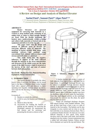
A Review on Design and Analysis of Bucket Elevator
Snehal Patel*, Sumant Patel**,Jigar Patel***
*, *** (Research Scholar, Department of Mechanical, Ganpat University, India
** (Assistant Professor, Department of Mechanical, Ganpat University, India
ABSTRACT
Bucket Elevators are powered
equipment for conveying bulk materials in a
vertical or steep inclined path, consisting of an
endless belt, or chain to which metallic buckets
are fixed. With the flexible belt/chain, the
buckets move unidirectionally within a casing
and collects bulk materials at bottom end of the
equipment and delivers it at the top end.
This paper deals with the design and
analysis of different parts of elevator for
conveying different types of materials. The
modeling of bucket elevator done using solid
modeling software and analyzed using
conventional finite element software (Ansys) and
stresses and deflections are obtained.
This study shows that the negative
influences of support of the shaft reflected
through the increase in the stress concentration
and occurence of the initial crack are the main
causes of the shaft fracture which is occurred at
the keyway of the shaft and zone of contact
between shaft and gearbox.
Keywords - Bucket Elevator, Material Handling
Figure 1 Schematic Diagram Of Bucket
Equipment, Stress Concentration
Elevator
I. INTRODUCTION A bucket elevator can elevate a variety of
The bucket elevator is probably the oldest bulk materials from light to heavy and from fine to
known form of conveyor, Its history can be traced large lumps. A centrifugal discharge elevator may
back to the days of Babylon where wicker baskets be vertical or inclined. Vertical elevators depend
lined with a natural pitch and fastened to ropes entirely on the action of centrifugal force to get the
operating over wooden sheaves turned by slaves, material into the discharge chute and must be run at
were used for the elevating of water into irrigation speeds relatively high. Inclined elevators with
ditches. buckets spaced apart or set close together may have
the discharge chute set partly under the head pulley.
It consists of: Since they don't depend entirely on the centrifugal
1) Buckets to contain the material; force to put the material into the chute, the speed
2) A belt to carry the buckets and transmit the may be relatively lower.
pull; Nearly all centrifugal discharge elevators
3) Means to drive the belt; have spaced buckets with rounded bottoms. They
4) Accessories for loading the buckets or pick up their load from a boot, a pit, or a pile of
picking up the material, for receiving the material at the foot pulley. The buckets can be also
discharged material, for maintaining the triangular in cross section and set close to on the
belt tension and for enclosing and belt with little or no clearance between them. This is
protecting the elevator as shown in fig 1 a continuous bucket elevator. Its main use is to carry
difficult materials at slow speed. Early bucket
elevators used a flat chain with small, steel buckets
attached every few inches. Current construction uses
a rubber belt with plastic buckets. Pulleys several
feet in diameter are used at the top and bottom. The
18 | P a g e
2. Snehal Patel, Sumant Patel, Jigar Patel / International Journal of Engineering Research and
Applications (IJERA) ISSN: 2248-9622 www.ijera.com
Vol. 2, Issue 5, September- October 2012, pp.018-022
top pulley is driven by an electric motor. The bucket Figure 3 Effect of radius of curvature (RC) on stress
elevator is the enabling technology that permitted distribution using FEM
the construction of grain elevators. A diverter at the
top of the elevator allows the grain to be sent to the
chosen bin.[1]
II. FEA ANALYSIS
A. Göksenli, I.B. Eryürek were carried out
failure analysis of an elevator drive shaft. After
analysis it is found that failure occurred at the
keyway of the shaft as shown in fig 2
Figure 4 Effect of RC on stress distribution
Figure 2 Fracture surface
Microstructural, mechanical and chemical
properties of the shaft are determined. After visual
investigation of the fracture surface it is concluded
that fracture occurred due to torsional-bending
fatigue. Fatigue crack has initiated at the keyway
edge. Considering elevator and driving systems,
forces and torques acting on the shaft are
determined; stresses occurring at the failure surface
are calculated. Stress analysis is also carried out by Figure 5 Effect of RC on fatigue safety factor
using finite element method (FEM) and the results
are compared with the calculated values. Endurance By increasing radius of curvature even
limit and fatigue safety factor is calculated, fatigue from 0.5 mm to 2 mm would decrease stress value
cycle analysis of the shaft is estimated. By from 163 to 104 MPa and an increase in fatigue
increasing radius of curvature (RC) value, stresses safety factor from 1.05 to 1.78.
occurring at the keyway corner could be decreased Fig. 4 and 5 demonstrate that an increase of
effectively. To determine the effect of RC on stress radius of curvature would probably prevent the
distribution, finite element analysis is carried out. failure of the elevator drive shaft. In conclusion it is
By this examination, RC-value was increased determined that fracture of the shaft occurred due to
stepwise for visual analysis of decrease in stress faulty design or manufacturing of the keyway (low
values, which can be seen in Fig. 3. Dramatic radius of curvature), causing a high notch effect. Fig
decrease of stress values at keyway corner can be 5 Effect of RC on fatigue safety factor. [2]
clearly seen. For further investigation, the effect of Mile Savkovic´ a*, Milomir Gašic´ a, Miodrag
change in RC on stress and fatigue safety factor is Arsic´ b, Radovan Petrovic were carried out
analyzed in detail which can be seen in Figs. 4 and Analysis of the axle fracture of the bucket wheel
5. excavator. They examines the causes of bucket
wheel axle fractures. Experimental testing of the
chemical composition and mechanical properties of
the material used to make the bucket wheel axle and
metallographic inspections of the fracture surfaces
in the bucket wheel axle by means of electronic and
light microscope carried out and also done FEM
analysis of influences of disturbances on the manner
of support of the bucket wheel axle on the fracture.
The uniaxial stress field, according to the Huber-
Hencky-von Mises hypothesis [3] of the load, is
presented in Fig 6
19 | P a g e
3. Snehal Patel, Sumant Patel, Jigar Patel / International Journal of Engineering Research and
Applications (IJERA) ISSN: 2248-9622 www.ijera.com
Vol. 2, Issue 5, September- October 2012, pp.018-022
The level of the stress state in the zone of
axle fracture for the case of additional support of the
hollow shaft on the bucket wheel axle is very high.
The values of uniaxial stresses, at the point of
support are 3.1 times higher than the stresses for the
basic case of load.
Figure 7 Total vent area vs KSt value. Single leg
elevator
The vent spacing is calculated by assuming
that one vent is positioned in the boot and one in the
head of the elevator, and the remaining total vent
area is distributed along the elevator assuming each
vent has an area equal to the cross-sectional area of
the elevator.
Table 1 Vent spacing: Single Leg Elevator
Figure 6 Distribution of the uniaxial stress of the Kst bar Vent
axle Pstat bar g Pref bar g
m.s-1 Spacing(m)
From work they concluded the 150 0.05 1.0 19
metallographic examination of the fracture surface 0.5 10
show that the fracture did not occur due to any 0.10 1.0 14
errors in the material.
0.5 0.7
The bucket wheel axle fracture is caused by
175 0.05 1.0 7
improper elimination of axis misalignment of the
0.5 4
bucket wheel axle and thehollow shaft which
resulted in: 0.10 1.0 5
- An increased stress concentration in the bucket 0.5 4
wheel axle, 200 0.05 1.0 5
- A triple increase of uniaxial stresses in the axle, 0.5 3
- A quadruple decrease of the degree of safety of the 0.10 1.0 4
axle [4] 0.5 3
Holbrow *, G.A. Lunn** , A. Tyldesley ***
were carried out an experimental programme on the The vent spacings for several combination values of
explosion protection of bucket elevators by venting. KSt, Pred and Pstat taken from Fig.7 are listed in
Two bucket elevators were used in the work—a Table 1. The spacing read from Fig. 8 is rounded
single leg elevator and a twin-leg elevator. down to the nearest metre
Four dusts were used with KSt values up to 211 bar
m s-1 and dust clouds were produced by dust
injection and by normal operation. Four dusts were
used in the tests:
milk powder: KSt=86 bar m s-1, Pmax=7.4 bar g;
cornflour A: KSt=147 bar m s-1, Pmax=7.9 bar g;
cornflour B: KSt=211 bar m s-1, Pmax=8.0 bar g;
cornflour C: KSt=180 bar m s-1, Pmax=8.7 bar g.
In this study he shows in Fig 7 Single leg elevator
how the total vent area required limiting reduced
explosion pressures to 1.0 and 0.5 bar varies with
the KSt value when the value of Pstat is 0.1 and 0.05 Figure 8 Vent spacing as a function of total vent
bar. area. Single leg elevator
20 | P a g e
4. Snehal Patel, Sumant Patel, Jigar Patel / International Journal of Engineering Research and
Applications (IJERA) ISSN: 2248-9622 www.ijera.com
Vol. 2, Issue 5, September- October 2012, pp.018-022
In neither of the tests in which venting the boot or within the recommended spacing,
occurred did the reduced explosion pressure exceed whichever is the lesser. The spacing between vents
the vent opening pressure, which was 125–135 along the elevator is listed as a function of the dust
mbar. In the two tests where venting occurred, the KSt value, the vent burst pressure and the reduced
vent nearest the ignition position opened, along with explosion pressure in Table 6. For dusts with KSt
vents approximately 10–12 m from the ignition values of 150 bar m s-1 or less, a vent spacing of 6 m
positiona vent spacing of 14 m will limit reduced will limit the reduced explosion pressure to 300
explosion pressures to the vent bursting pressure if mbar, when the vent static burst pressure is 0.1 bar.
this is no greater than 0.10 bar. For dusts with KSt values of 100 bar m s-1 or less,
In Twin leg elevator the reduced explosion vents installed in the head and boot of the elevator,
pressure data for bucket spacing of 140 or 280 mm with none intervening, will limit the reduced
are combined in Fig. 9. This diagram may be used to explosion pressure to 0.5 bar. For dusts with KSt
estimate vent spacing providing: values of 80 bar m s-1 or less, a vent spacing of 14
(i) the vents open at a pressure not exceeding 100 m will limit the reduced explosion pressure to the
mbar; vent bursting pressure if this is no greater than 0.1
(ii) the area of the vent is not less than the cross- bar. For dusts with a KSt value of 80 bar m s-1, a
sectional area of the elevator leg; vent spacing of 20 m will limit the reduced
(iii) a vent is positioned at the head and a vent is explosion pressure to 250 mbar. In Twin leg
located as close as possible to the boot. elevator Vent openings should have area equal to
the crosssection of the elevator leg and the least
requirement is that vents should be fitted in the head
and as close as is practicable to the boot. This
generally means within 6 m of the boot or within the
recommended vent spacing, whichever is the lesser.
The static burst pressure of the vent closure should
not exceed 0.1 bar.The spacing of additional vents
depends on the KSt value of the dust. (a) Although
explosions are possible with dusts of low KSt,
generally the pressures developed by dusts with KSt
values below 100 bar m s-1 are not significant, and
no additional vents are required.
(b) Dusts with a KSt value of 150 bar m s-1
are able to develop significant pressures, although
the likelihood of explosion propagation through the
elevatoris low. Vents additional to those at the head
and boot may be required on long elevators if the
casing is comparatively weak. The graphs in Figs. 7
and 9 should be used to estimate the reduced
Figure 9 Explosion pressure vs vent spacing for
explosion pressure for a given KSt value and vent
twin leg elevator.Vent opening pressure=0.1 bar.
spacing.
(c) Dusts with KSt values above 150 bar m
The data suggest that a vent spacing of 10 m will
s-1 will propagate explosions, and vents additional to
limit the reduced explosion pressure to 1 bar for
those in the head and boot are required on elevators
dusts with KSt values between 150 and 175 bar m s-
1 taller than 6 m. The graphs in Figs. 7 and 9 should
and a spacing of 5 m is required for dusts with KSt
be used to estimate the reduced explosion pressure
values between 175 and 200 bar m s-1. For dusts
for a given KSt value and vent spacing. The strength
with KSt values between 100 and 150 bar m s-1, a
of the elevator should then be designed
spacing of 14 m will limit the pressure to 1 bar. For
appropriately.
dusts with KSt values below 100 bar m s-1, the
(d) No data are available for dusts with KSt values
reduced explosion pressure does not exceed the
greater than 210 bar m s-1. [5]
bursting pressure of the vent cover even at very high
vent spacing.
After the result he conclude that in Single III. CONCLUSION
leg elevator Vent openings should have an area From study we concluded that there is a
equal to the crosssectional area of the elevator leg fracture on shaft at key way and area where abrupt
and the minimum requirement is that vents should change in cross-sectional area occur due to high
be fitted in the head and as close as is practicable to stress
the boot. This generally means a vent within 6 m of
Concentration and also the other parts of
elevator. So decrease in stress concentration is
achieved by modified design.
21 | P a g e
5. Snehal Patel, Sumant Patel, Jigar Patel / International Journal of Engineering Research and
Applications (IJERA) ISSN: 2248-9622 www.ijera.com
Vol. 2, Issue 5, September- October 2012, pp.018-022
REFERENCES
[1] Woodcock. C. R, J. S. Mason, ―Bulk
Solids Handling: An Introduction to the
Practice and Technology‖.
[2] A. Göksenli, I.B. Eryürek, ―Failure
analysis of an elevator drive shaft‖
science direct ,Engineering Failure
Analysis 16 (2009) 1011–1019.
[3] Rusinski E, Harnatkiewicz P, Bobyr B,
Yakhno B. Caterpillar drive shaft damage
causes analysis. Arch Civ Mech Eng
2008;VIII(3):117–29.
[4] Mile Savkovic a, Milomir Gašic´ a,
Miodrag Arsic´ b, Radovan Petrovic´ a,‖
Analysis of the axle fracture of the bucket
wheel excavator ― sience Engineering
Failure Analysis 18 (2011) 433–441.
[5] P. Holbrow a, G.A. Lunn a*, A. Tyldesley
b ‖ Explosion venting of bucket
elevators ―,science direct, Journal of Loss
Prevention in the Process Industries 15
(2002) 373–383.
22 | P a g e

![Snehal Patel, Sumant Patel, Jigar Patel / International Journal of Engineering Research and
Applications (IJERA) ISSN: 2248-9622 www.ijera.com
Vol. 2, Issue 5, September- October 2012, pp.018-022
top pulley is driven by an electric motor. The bucket Figure 3 Effect of radius of curvature (RC) on stress
elevator is the enabling technology that permitted distribution using FEM
the construction of grain elevators. A diverter at the
top of the elevator allows the grain to be sent to the
chosen bin.[1]
II. FEA ANALYSIS
A. Göksenli, I.B. Eryürek were carried out
failure analysis of an elevator drive shaft. After
analysis it is found that failure occurred at the
keyway of the shaft as shown in fig 2
Figure 4 Effect of RC on stress distribution
Figure 2 Fracture surface
Microstructural, mechanical and chemical
properties of the shaft are determined. After visual
investigation of the fracture surface it is concluded
that fracture occurred due to torsional-bending
fatigue. Fatigue crack has initiated at the keyway
edge. Considering elevator and driving systems,
forces and torques acting on the shaft are
determined; stresses occurring at the failure surface
are calculated. Stress analysis is also carried out by Figure 5 Effect of RC on fatigue safety factor
using finite element method (FEM) and the results
are compared with the calculated values. Endurance By increasing radius of curvature even
limit and fatigue safety factor is calculated, fatigue from 0.5 mm to 2 mm would decrease stress value
cycle analysis of the shaft is estimated. By from 163 to 104 MPa and an increase in fatigue
increasing radius of curvature (RC) value, stresses safety factor from 1.05 to 1.78.
occurring at the keyway corner could be decreased Fig. 4 and 5 demonstrate that an increase of
effectively. To determine the effect of RC on stress radius of curvature would probably prevent the
distribution, finite element analysis is carried out. failure of the elevator drive shaft. In conclusion it is
By this examination, RC-value was increased determined that fracture of the shaft occurred due to
stepwise for visual analysis of decrease in stress faulty design or manufacturing of the keyway (low
values, which can be seen in Fig. 3. Dramatic radius of curvature), causing a high notch effect. Fig
decrease of stress values at keyway corner can be 5 Effect of RC on fatigue safety factor. [2]
clearly seen. For further investigation, the effect of Mile Savkovic´ a*, Milomir Gašic´ a, Miodrag
change in RC on stress and fatigue safety factor is Arsic´ b, Radovan Petrovic were carried out
analyzed in detail which can be seen in Figs. 4 and Analysis of the axle fracture of the bucket wheel
5. excavator. They examines the causes of bucket
wheel axle fractures. Experimental testing of the
chemical composition and mechanical properties of
the material used to make the bucket wheel axle and
metallographic inspections of the fracture surfaces
in the bucket wheel axle by means of electronic and
light microscope carried out and also done FEM
analysis of influences of disturbances on the manner
of support of the bucket wheel axle on the fracture.
The uniaxial stress field, according to the Huber-
Hencky-von Mises hypothesis [3] of the load, is
presented in Fig 6
19 | P a g e](data:image/gif;base64,R0lGODlhAQABAIAAAAAAAP///yH5BAEAAAAALAAAAAABAAEAAAIBRAA7)