Microstrip Antenna for ISM Band (2.4GHz) Applications-A review
•
1 like•832 views

The past decade has seen a rapid development of wireless communication systems. This continuous trend is bringing about a wave of new wireless devices placing several demands on the antenna such as size miniaturization, power consumption, simplicity, compatibility with printed-circuit technology, low profile, light weight, lower return loss and good radiation properties. This paper provides a comprehensive review of the research work done in the recent past by various authors on the design and optimization of the planar microstrip antenna operating in ISM band. An exhaustive list of reference has been provided.
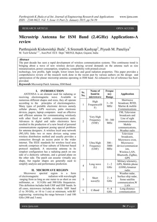
![Parthrajsinh K Jhala et al Int. Journal of Engineering Research and Applications www.ijera.com
ISSN : 2248-9622, Vol. 5, Issue 1( Part 2), January 2015, pp.54-59
www.ijera.com 55 | P a g e
7 X-Band
8 - 12
GHz
Satellite
communication,
Terrestrial
broadcast radar,
Space
communication,
Amateur radio
8 Ku-Band
12 - 18
GHz
Satellite
communication
9 K-Band
18 - 27
GHz
Astronomical
observation,
Automotive radar,
Satellite
communication,
Radar
10 Ka-Band
27 - 40
GHz
Satellite
communication
11 V-Band
40 - 75
GHz
Millimeter wave
radar research and
other kinds of
Scientific research
12 W-Band
75-110
GHz
Millimeter wave
radar research,
Military radar
targeting and
tracking
applications,
Satellite
communication,
Non-military
communication
13
Millimeter-
Band
110 -
300
GHz
Millimeter scanner,
DBS, Direct-
energy weapon,
Satellite television
broadcasting,
Amateur radio
Table 1 : Various bands of microwave region
2.1 Importance
Antenna gain is proportional to the electrical size
of the antenna. At higher frequencies, more
antenna gain can be obtained for a given physical
antenna size, and this has important
consequences when implementing microwave
systems.[3]
More bandwidth (directly related to data rate)
can be realized at higher frequencies.[2,3]
Line of sight communication is of prime
focusing case of microwave frequency signals as
they are not bent by the ionosphere as are lower
frequency signals. Satellite and terrestrial
communication links with very high capacities
are therefore possible, with frequency reuse at
minimally distant locations.[2]
Various molecular, atomic and nuclear
resonances occur at microwave frequencies,
creating a variety of unique applications in the
areas of basic science, remote sensing, medical
diagnostics & treatment and heating methods.[4]
2.2 Microwave Devices
2.2.1 Waveguides:
Any linear hollow metallic structure which
confines microwave energy signals by channeling
them satisfactorily from one point to another with the
aid of multiple reflections between the opposite
walls of the structure can be defined as a
waveguide.[2,4] Various prevailing waveguides are
rectangular waveguides and circular waveguides
2.2.1.1 Rectangular waveguide
Rectangular waveguides are one of the earliest
types of transmission lines used to transport
microwave signals and used for many applications.
Rectangular waveguides can propagate TM and TE
modes but not TEM waves since only one conductor
is present.[1,2] The TM and TE modes of a
rectangular waveguide have cutoff frequencies below
which propagation is not possible.
2.2.1.2Circular waveguide
A hollow, round metal pipe supports TE and TM
waveguide modes. Dominant mode for circular
waveguide is TE11 mode. In this waveguide TE10
mode cannot be propagated but TE01 mode can be
propagated.[4]
2.2.1.3 Ridge waveguide
The ridge waveguide consists of a rectangular
waveguide loaded with conducting ridges on the top
and/or bottom walls. This loading tends to lower the
cut-off frequency of the dominant mode, leading to
increased bandwidth and better impedance
characteristics. Ridge waveguides are often used for
impedance matching purposes, where the ridge may
be tapered along the length of the guide, but the
power handling capacity gets decreased.[1]
2.2.1.4 Coplanar waveguide
The coplanar waveguide can be viewed as a slot
line with a third conductor centered in the slot region.
Due to the presence of the additional conductor, it
can support even or odd quasi-TEM modes,
depending on the direction of the electric fields in the
two slots .[1]
2.2.2Couplers:
A directional coupler is a passive device which
couples part of the transmission power by a known
amount out through another port by setting two
transmission lines close enough together such that
energy passing through one is coupled to the other.
There are some different types of waveguide
directional couplers.[2]](data:image/gif;base64,R0lGODlhAQABAIAAAAAAAP///yH5BAEAAAAALAAAAAABAAEAAAIBRAA7)
Recommended
Recommended
More Related Content
What's hot
What's hot (18)
Viewers also liked
Viewers also liked (20)
Similar to Microstrip Antenna for ISM Band (2.4GHz) Applications-A review
Similar to Microstrip Antenna for ISM Band (2.4GHz) Applications-A review (20)
Recently uploaded
Recently uploaded (20)
Microstrip Antenna for ISM Band (2.4GHz) Applications-A review
- 1. Parthrajsinh K Jhala et al Int. Journal of Engineering Research and Applications www.ijera.com ISSN : 2248-9622, Vol. 5, Issue 1( Part 2), January 2015, pp.54-59 www.ijera.com 54 | P a g e Microstrip Antenna for ISM Band (2.4GHz) Applications-A review Parthrajsinh Kishorsinhji Jhala1 , S.Sreenath Kashyap2 , Piyush M. Paneliya3 M. Tech Scholar1, 3 , Asst.Prof. ECE Dept.2 MEFGI, Rajkot, Gujarat, India Abstract The past decade has seen a rapid development of wireless communication systems. This continuous trend is bringing about a wave of new wireless devices placing several demands on the antenna such as size miniaturization, power consumption, simplicity, compatibility with printed-circuit technology, low profile, light weight, lower return loss and good radiation properties. This paper provides a comprehensive review of the research work done in the recent past by various authors on the design and optimization of the planar microstrip antenna operating in ISM band. An exhaustive list of reference has been provided. Keywords-Microstrip Patch Antenna, ISM Band. I. INTRODUCTION ANTENNA is an element used for radiating or receiving electromagnetic wave. Available in numerous different shapes and sizes, they all operate according to the principles of electromagnetics. Many types of portable electronic devices namely cellular phones, GPS receivers, palm electronic devices, pagers, laptop computers need an effective and efficient antenna for communicating wirelessly with other fixed or mobile communication units. Advances in digital and radio electronics have resulted in the production of a new breed of personal communications equipment posing special problems for antenna designers. A wireless local area network (WLAN) links two or more devices using some wireless distribution method and usually provides a connection through an access point to the wider internet. The IEEE standards for wireless local area network comprises of four subsets of Ethernet based protocol standards. A microstrip antenna in its simplest configuration has a radiating patch on one side of a dielectric substrate, and a ground plane on the other side. The patch can assume virtually any shape, but regular shapes are generally used to simplify analysis and performance prediction. II. MICROWAVE REGION Microwave spectral region is a form of electromagnetic radiation with wavelength ranging from as long as one meter to as short as one millimeter, or 0.3 GHz and 300 GHz frequencies. This definition includes both UHF and EHF bands. In all cases, microwave includes the whole SHF band (3 to 30 GHz, or 10 to 1 cm) at minimum, with RF engineering restricting the range between 1 and 100 GHz (300 and 3 mm). Sr. No. Name of band in microwave Freque ncy Range Application 1 High Frequency(H F) 3 - 30 MHz Shortwave broadcast, RFID, Marine & mobile Communications 2 Very High Frequency (VHF) 30 - 300 MHz FM, Television broadcasts and Line of sight communications, Mobile communications, Weather radio 3 Ultra High Frequency (UHF) 300 - 3000 MHz Television broadcasts, Microwave oven, Microwave- device/communicat ion, Wireless LAN, Bluetooth, ZigBee, GPS 4 Long wave (L) 1 - 2 GHz Military telemetry, GPS, Mobile phone (GSM),Amateur radio 5 Short wave(S) 2 - 4 GHz Weather radar, Surface ship radar, Some satellite communication,W LAN 6 C-Band 4 - 8 GHz Long distance communication RESEARCH ARTICLE OPEN ACCESS
- 2. Parthrajsinh K Jhala et al Int. Journal of Engineering Research and Applications www.ijera.com ISSN : 2248-9622, Vol. 5, Issue 1( Part 2), January 2015, pp.54-59 www.ijera.com 55 | P a g e 7 X-Band 8 - 12 GHz Satellite communication, Terrestrial broadcast radar, Space communication, Amateur radio 8 Ku-Band 12 - 18 GHz Satellite communication 9 K-Band 18 - 27 GHz Astronomical observation, Automotive radar, Satellite communication, Radar 10 Ka-Band 27 - 40 GHz Satellite communication 11 V-Band 40 - 75 GHz Millimeter wave radar research and other kinds of Scientific research 12 W-Band 75-110 GHz Millimeter wave radar research, Military radar targeting and tracking applications, Satellite communication, Non-military communication 13 Millimeter- Band 110 - 300 GHz Millimeter scanner, DBS, Direct- energy weapon, Satellite television broadcasting, Amateur radio Table 1 : Various bands of microwave region 2.1 Importance Antenna gain is proportional to the electrical size of the antenna. At higher frequencies, more antenna gain can be obtained for a given physical antenna size, and this has important consequences when implementing microwave systems.[3] More bandwidth (directly related to data rate) can be realized at higher frequencies.[2,3] Line of sight communication is of prime focusing case of microwave frequency signals as they are not bent by the ionosphere as are lower frequency signals. Satellite and terrestrial communication links with very high capacities are therefore possible, with frequency reuse at minimally distant locations.[2] Various molecular, atomic and nuclear resonances occur at microwave frequencies, creating a variety of unique applications in the areas of basic science, remote sensing, medical diagnostics & treatment and heating methods.[4] 2.2 Microwave Devices 2.2.1 Waveguides: Any linear hollow metallic structure which confines microwave energy signals by channeling them satisfactorily from one point to another with the aid of multiple reflections between the opposite walls of the structure can be defined as a waveguide.[2,4] Various prevailing waveguides are rectangular waveguides and circular waveguides 2.2.1.1 Rectangular waveguide Rectangular waveguides are one of the earliest types of transmission lines used to transport microwave signals and used for many applications. Rectangular waveguides can propagate TM and TE modes but not TEM waves since only one conductor is present.[1,2] The TM and TE modes of a rectangular waveguide have cutoff frequencies below which propagation is not possible. 2.2.1.2Circular waveguide A hollow, round metal pipe supports TE and TM waveguide modes. Dominant mode for circular waveguide is TE11 mode. In this waveguide TE10 mode cannot be propagated but TE01 mode can be propagated.[4] 2.2.1.3 Ridge waveguide The ridge waveguide consists of a rectangular waveguide loaded with conducting ridges on the top and/or bottom walls. This loading tends to lower the cut-off frequency of the dominant mode, leading to increased bandwidth and better impedance characteristics. Ridge waveguides are often used for impedance matching purposes, where the ridge may be tapered along the length of the guide, but the power handling capacity gets decreased.[1] 2.2.1.4 Coplanar waveguide The coplanar waveguide can be viewed as a slot line with a third conductor centered in the slot region. Due to the presence of the additional conductor, it can support even or odd quasi-TEM modes, depending on the direction of the electric fields in the two slots .[1] 2.2.2Couplers: A directional coupler is a passive device which couples part of the transmission power by a known amount out through another port by setting two transmission lines close enough together such that energy passing through one is coupled to the other. There are some different types of waveguide directional couplers.[2]
- 3. Parthrajsinh K Jhala et al Int. Journal of Engineering Research and Applications www.ijera.com ISSN : 2248-9622, Vol. 5, Issue 1( Part 2), January 2015, pp.54-59 www.ijera.com 56 | P a g e 2.2.2.1 Bethe Hole Coupler The directional property of all directional couplers is produced through the use of two separate waves or wave components, which add in phase at the coupled port and are canceled at the isolated port. One of the simplest ways of doing this is to couple one waveguide to another through a single small hole in the common broad wall between the two waveguides. Such a coupler is known as a Bethe hole coupler.[2,4] 2.2.2.2 Multi-hole coupler If the coupler is designed with a series of coupling holes and the extra degrees of freedom can be used to increase this bandwidth such a couplers is called multi-hole coupler.[1] 2.2.2.3 Quadrature Hybrid Coupler The quadrature hybrid coupler is 3 dB directional coupler with a 90◦ phase difference in the outputs of the through and coupled arms.[4] 2.2.2.4. Coupled Line Directional Coupler When two unshielded transmission lines are in close proximity, power can be coupled from one line to the other due to the interaction of the electromagnetic fields. Such lines are referred to as coupled transmission lines with coupled line directional coupler.[1] 2.2.3 Antennas An antenna is an electrical device that is used to convert electric power into radio waves, and vice versa. Antennas are essential components of all that uses radio system. They are used in systems such as radio broadcasting, broadcast television, two-way radio, communications receivers, radar, cell phones, and satellite communications, as well as other devices such as garage door openers, wireless microphones, Bluetooth-enabled devices, wireless computer networks, baby monitors, and RFID tags on merchandise.[3] Comparison of some different types of antennas are given as in Table 2 below. Antenna Type/ Paramet er Mono pole Slot Microst rip Patch PIFA Radiatio n Pattern Omni- Directi onal Roughl y omni- directio nal Directio nal Omni - direct ional Gain High Moderat e High Mode rate to high Modelin g & Fabricati on Model ing is difficu lt Fabricat ion on PCB can be done Easier to fabricat e and model Easier fabric ation using PCB Applicati on Radio broadc ast, Vehic ular antenn a Radar, Cell phone base station Satellite commu ni- cation, Aircraft s Intern al anten nas of mobil e phone s Merits Comp act size, Low fabrica tion cost, Large bandw idth suppor t Radiatio n characte ristics remains unchang ed due to tuning, Design simplici ty Low cost, Low weight, Easy in integrati on Small size, Low cost, Redu ced back ward radiat ion for mini mizin g SAR Problem s Diffic ult fabrica tion at higher freque ncies (>3 GHz) Size constrai nt for mobile handhel d devices No bandpas s filtering effect, Surface- area require ment Narro w band width chara cterist ics Table 2 : Comparison of various antennas III. RELATED WORK The recent development of different techniques in design of antennas enabled a breakthrough in many different area of science and technology. Microstrip patch antenna has gained attraction for wide application in microwave frequencies. Eng Gee Lim, Zhao Wang et.al. have attempted to design a triple band h-slot antenna by using feed line technique.[5] The bands covered are GSM mobile phone system (0.9 and 1.8 GHz) and ISM band which is used for Bluetooth and wireless local area network bands applications. The CST microwave studio software is used as a tool for simulation.
- 4. Parthrajsinh K Jhala et al Int. Journal of Engineering Research and Applications www.ijera.com ISSN : 2248-9622, Vol. 5, Issue 1( Part 2), January 2015, pp.54-59 www.ijera.com 57 | P a g e Figure 1: A triple band h-slot antenna[5] This antenna is an attractive candidate for important applications like mobile phone communication systems, mobile phone jammer application, and so on. The measured 10 dB return loss bandwidth of the antenna ISM bands was 85 MHz (2.4 GHz-2.485 GHz) Md. Ashikur Rahman, Asif Shaikat, Ibnul Sanjid Iqbal, Asif Hassan have presented the design and analysis of a wideband microstrip patch antenna[6] Figure 2: Wideband inset feeded Antenna Geometry [6] for performance in the unlicensed Industrial, Scientific and Medical (ISM) band (2.45 GHz) applications e.g., Radio Frequency Identification Application (RFID) applications. The Flame Retardant-4 (FR-4) material is used as substrate and the size is 29×46. This antenna has a gain of 3.019dB with VSWR of almost 1.3 and HPBW of about 111.3 deg with an ultra-wide bandwidth of about 21.67% with resonant frequency at 2.4 GHz. It is designed and simulated in CST Microwave Studio software. S.Sreenath Kashyap et.al. designed a simple microstrip patch antenna using different substrate material which enables antenna for ISM Band application.[11] Ajmal Hussain Shah, Surendran Subramaniam and others proposed a Tri-band G-shaped Microstrip Monopole antenna suitable for the ISM band wireless applications in MIMO environment.[7] Figure 3: Geometry of the G-shaped Antenna[7] In this paper, the design and analysis of a novel G-shaped monopole antenna with CPW feed for bandwidth improvement at lower-band frequency range, mid-band frequency range and the upper-band frequency range of the ISM band in MIMO environment is presented. The antenna design parameters are optimized to achieve a bandwidth improvement at 2.4 GHz, 4.2 GHz, and 6.07 GHz as the center frequencies with return loss of -44 db at 2.4 GHz. Very recently Dr. Vedvyas Dwivedi, Y.P.Costa & team designed an antenna using metamaterial. An S shape structured metamaterial antenna for 2.4GHz is designed which enhances potential application in wireless communication.[10] Swati Singh, Rajesh Kumar Gangwar and Sweta Agarwal have proposed a T shaped dualband microstrip antenna fed by coaxial feed for wearable applications in the ISM band (2.4-2.5GHz,5.7- 5.8GHz).[8] Figure 4:Geometry of the T-shaped dualband antenna[8] This antenna provides dual band performance.As for the wearable applications, felt is used as the
- 5. Parthrajsinh K Jhala et al Int. Journal of Engineering Research and Applications www.ijera.com ISSN : 2248-9622, Vol. 5, Issue 1( Part 2), January 2015, pp.54-59 www.ijera.com 58 | P a g e substrate to make sure the antenna can bend following human body. The overall size of the proposed antenna is 44mm*36mm*3mm. Different parameters like Return loss, Voltage Standing Wave Ratio(VSWR), Impedance, Directivity and Gain are measured and discussed using Zealand IE3D simulation software. The simulated return loss is - 25.2db at 2.46GHz. Ahmed Al-Shaheen has proposed a new patch antenna as a hexagonal patch which operates in the Industrial Scientific Medical (ISM) frequency band at 2.45 GHz.[9] Figure 5:Geometry of the hexagonal line fed antenna[9] The proposed antenna is verified using two different numerical techniques which are Finite Element Method FEM and Method of Moment MoM, the compression results showed good agreement. When human body is presented near the antenna the antenna performance such as S11 and bandwidth are affected,but the result depicted that the new antenna has negligible effect compared to that of the rectangular patch antenna.The simulated return loss is found to be -16.8 db in air whereas near a human body it got negligibly reduced to-15 db. IV. CONCLUSION Antenna has gained prime importance in the field of communication, security, material testing, and sensing application. New types of electronic and photonic structures are needed for efficient communication. Table1 represents the various bands of EM spectrum along with its application. This paper reviewed a selection of state-of-the-art microstrip patch antennas operating in ISM band of varying types, shapes and feeds. The design aspect such as dimension will play a significant role in determining resonant frequency. Despite of obstacles the potential for new valuable application is driving towards research in communication through ISM Band in 2.4 GHz. REFERENCES [1]. Balanis C. A, “Microstrip Antennas”, Antenna Theory, Analysis and Design, Third Edition, John Wiley & Sons, pp-811- 876, 2010 [2]. David M. Pozar ,” Microwave Engineering”, Fourth Edition, John Wiley & Sons, pp-96-379,2012 [3]. Ramesh Garg , Prakash Bhartia , Inder Bahl, Apisak Ittipiboon, “Microstrip Antenna Design Handbook”, Artech House Inc. Norwood, MA, pp. 1-68, 253-316, 2001. [4]. Dr M.Kulkarni,”Microwave and Radar Engineering”,Fifth Edition, John Wiley & Sons, pp 61-262,2014. [5]. Eng Gee Lim, Zhao Wang, Jing Chen Wang, Mark Leach, Rong Zhou, Chi-Un Lei and Ka Lok Man” Wearable Textile Substrate Patch Antennas”, Engineering Letters, 22:2, EL_22_2_08, Advance online publication 27 May 2014. [6]. Md. Ashikur Rahman, Asif Shaikat, Ibnul Sanjid Iqbal, Asif Hassan,” Microstrip Patch Antenna Design and Performance Analysis for RFID applications at ISM band (2.45GHz)”,Proceedings of 2013 2nd International Conference on Advances in Electrical Engineering (ICAEE 2013)19-21 December, 2013. [7]. Ajmal Hussain Shah, Surendran Subramaniam, Sathish Kumar Selvaperumal, Asadullah Shah, Sheroz Khan,”Design and Analysis of a Tri-band G- shaped Monopole Antenna for Bandwith Improvement for Wireless Applications of Measurement Parameters in MIMO Environment”, Proc. of the IEEE International Conference on Smart Instrumentation, Measurement and Applications (ICSIMA) 26-27 November 2013. [8]. Swati Singh, Rajesh Kumar Gangwar and Sweta Agarwal” A Dualband T-Shaped Microstrip Antenna for Wearable Application”, International Journal of Electronic And Electrical Engineering, 2014. [9]. Ahmed Al-Shaheen,”New Patch Antenna For ISM Band At 2.45 Ghz”,ARPN Journal of Engineering and Applied Sciences,2012. [10]. Vedvyas Dwivedi, Y.P. Costa, Rajeev Jyoti,”An investigation and application
- 6. Parthrajsinh K Jhala et al Int. Journal of Engineering Research and Applications www.ijera.com ISSN : 2248-9622, Vol. 5, Issue 1( Part 2), January 2015, pp.54-59 www.ijera.com 59 | P a g e issues of miniaturized compact MSTPA for RF Communication system using metamaterial : A Study”IEEE International RF and Microwave Conference Proceddings, December 2-4,2008,Malasiya [11]. S.Sreenath Kashyap , B,Saisandeep,”Design and development of microstrip patch antenna for 2.4GHz”,International Journal of Scientific and Engineearing research,June 2012. [12]. Harish Kumar, Rjeev K. Kanth, Pasi Liljeberg, and Hannu Tenhunen,” Metamaterial Based Slotted PatchAntenna”,IEEE,2011. [13]. Omar Noori, Jalel Chebil, Md. Rafiqul Islam and Sheroz Khan” Design of a Triple-Band h Slot Patch Antenna” IEEE International RF & Microwave conference,2011. [14]. P.Muthu Kannan,V.Palanisamy,”Dual Band Rectangular Patch Wearable Antenna on Jeans Material”,International Journal of Engineering and Technology,2011-2012. [15]. Parminder Singh,Charvi Sharma,Neha Dutta,Chanchal Mahajan”Multi Band Microstrip Patch Antenna for WiMax and Bluetooth Applications”, International Journal of Engineering Innovation & Research,2012. [16]. Swaraj Panusa,Mithlesh Kumar”Quad-Band U-Slot Microstrip Patch Antenna”, International Journal of & Scientific Research Engineering Technology (IJSRET),2014. [17]. Yogesh Kumar Choukiker, S K Behera, B K Pandey, R Jyoti,”Optimization of Planar Antenna for ISM Band Using Particle Swarm Optimization Technique”, INTERNATIONAL JOURNAL OF ICROWAVE AND OPTICAL TECHNOLOGY,2014.