Mb3620672070

International Journal of Engineering Research and Applications (IJERA) aims to cover the latest outstanding developments in the field of all Engineering Technologies & science. International Journal of Engineering Research and Applications (IJERA) is a team of researchers not publication services or private publications running the journals for monetary benefits, we are association of scientists and academia who focus only on supporting authors who want to publish their work. The articles published in our journal can be accessed online, all the articles will be archived for real time access. Our journal system primarily aims to bring out the research talent and the works done by sciaentists, academia, engineers, practitioners, scholars, post graduate students of engineering and science. This journal aims to cover the scientific research in a broader sense and not publishing a niche area of research facilitating researchers from various verticals to publish their papers. It is also aimed to provide a platform for the researchers to publish in a shorter of time, enabling them to continue further All articles published are freely available to scientific researchers in the Government agencies,educators and the general public. We are taking serious efforts to promote our journal across the globe in various ways, we are sure that our journal will act as a scientific platform for all researchers to publish their works online.

Recommended
Recommended
More Related Content
What's hot
What's hot (13)
Viewers also liked
Viewers also liked (20)
Similar to Mb3620672070
Similar to Mb3620672070 (20)
Recently uploaded
Recently uploaded (20)
Mb3620672070
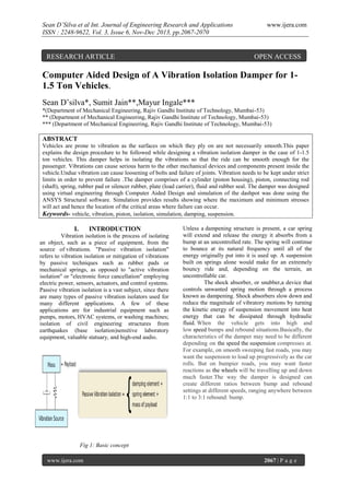
- 1. Sean D’Silva et al Int. Journal of Engineering Research and Applications ISSN : 2248-9622, Vol. 3, Issue 6, Nov-Dec 2013, pp.2067-2070 RESEARCH ARTICLE www.ijera.com OPEN ACCESS Computer Aided Design of A Vibration Isolation Damper for 11.5 Ton Vehicles. Sean D’silva*, Sumit Jain**,Mayur Ingale*** *(Department of Mechanical Engineering, Rajiv Gandhi Institute of Technology, Mumbai-53) ** (Department of Mechanical Engineering, Rajiv Gandhi Institute of Technology, Mumbai-53) *** (Department of Mechanical Engineering, Rajiv Gandhi Institute of Technology, Mumbai-53) ABSTRACT Vehicles are prone to vibration as the surfaces on which they ply on are not necessarily smooth.This paper explains the design procedure to be followed while designing a vibration isolation damper in the case of 1-1.5 ton vehicles. This damper helps in isolating the vibrations so that the ride can be smooth enough for the passenger. Vibrations can cause serious harm to the other mechanical devices and components present inside the vehicle.Undue vibration can cause loosening of bolts and failure of joints. Vibration needs to be kept under strict limits in order to prevent failure .The damper comprises of a cylinder (piston housing), piston, connecting rod (shaft), spring, rubber pad or silencer rubber, plate (load carrier), fluid and rubber seal. The damper was designed using virtual engineering through Computer Aided Design and simulation of the dashpot was done using the ANSYS Structural software. Simulation provides results showing where the maximum and minimum stresses will act and hence the location of the critical areas where failure can occur. Keywords- vehicle, vibration, piston, isolation, simulation, damping, suspension. I. INTRODUCTION Vibration isolation is the process of isolating an object, such as a piece of equipment, from the source of vibrations. "Passive vibration isolation" refers to vibration isolation or mitigation of vibrations by passive techniques such as rubber pads or mechanical springs, as opposed to "active vibration isolation" or "electronic force cancellation" employing electric power, sensors, actuators, and control systems. Passive vibration isolation is a vast subject, since there are many types of passive vibration isolators used for many different applications. A few of these applications are for industrial equipment such as pumps, motors, HVAC systems, or washing machines; isolation of civil engineering structures from earthquakes (base isolation)sensitive laboratory equipment, valuable statuary, and high-end audio. Unless a dampening structure is present, a car spring will extend and release the energy it absorbs from a bump at an uncontrolled rate. The spring will continue to bounce at its natural frequency until all of the energy originally put into it is used up. A suspension built on springs alone would make for an extremely bouncy ride and, depending on the terrain, an uncontrollable car. The shock absorber, or snubber,a device that controls unwanted spring motion through a process known as dampening. Shock absorbers slow down and reduce the magnitude of vibratory motions by turning the kinetic energy of suspension movement into heat energy that can be dissipated through hydraulic fluid. When the vehicle gets into high and low speed bumps and rebound situations.Basically, the characteristics of the damper may need to be different depending on the speed the suspension compresses at. For example, on smooth sweeping fast roads, you may want the suspension to load up progressively as the car rolls. But on bumpier roads, you may want faster reactions as the wheels will be travelling up and down much faster.The way the damper is designed can create different ratios between bump and rebound settings at different speeds, ranging anywhere between 1:1 to 3:1 rebound: bump. Fig 1: Basic concept www.ijera.com 2067 | P a g e
- 2. Sean D’Silva et al Int. Journal of Engineering Research and Applications ISSN : 2248-9622, Vol. 3, Issue 6, Nov-Dec 2013, pp.2067-2070 www.ijera.com vibration. However, if the system is subject to a loading force, equation (1) now becomes 𝑀𝑥 + 𝐶𝑥 + 𝐾𝑥 = 𝐹 (2) (Inertia (damping (spring (Loading) Force) Force) Force) These fundamental representations could be used for a variety of practical modeling and design exercises. In particular, one can frequently obtain helpful initial information on structural and machine natural frequencies, vibration transmissibility, effectiveness of simple dampers and absorbers (Mathew, 1990). Fig 2: Damper graph Design for Piston Thickness In designing for piston thickness, it is assumed that the diameter of the piston is that of the cylinder with a considerable length. In order to withstand the load, the equation, 3𝐹 𝑡= (3) 4𝑆 Where t = thickness of piston, (m); F = force of load, (N) and S = yield stress of the material Design for the Piston Rod Diameter The piston rod diameter is got through the expression given by Lingaiah and Narayan (1973) Fig 3: Location on the vehicle II. DESIGN CALCULATION Any vibration isolation device has an interface to the structure being isolated from vibration sources. This interface can be approximately taken as a single point in many cases either for its sufficiently small area or for its high-enough stiffness that the interface can be considered as rigid body. In such cases, the single degree of freedom model is the most widely used approach to represent a vibration isolation system (Liang and Wenhu, 2008). The design is based on the consideration of a single degree freedom system figure 3 formed by a rigid mass in resting on a spring of stiffness K and a viscous damper having damping coefficient C. a system is said to be of a single degree when its motion is constrained to one direction Let the system be set in motion by giving an initial velocity to the mass, thus the equation of motion for the free vibration of the system is 𝑀𝑥 + 𝐶𝑥 + 𝐾𝑥 = 0 (1) (Inertia (damping (spring Force) Force) Force) Where x = displacement 𝑥 = the velocity of the mass 𝑥 = acceleration of the mass (Adeyeri, 2001) In equation1, the right hand side equals zero since there is no external force on the system during www.ijera.com Dip = 1.9 to 2.5Dc Where Dip= the piston inside diameter Dc= diameter of the connecting rod (4) Design of Piston’s Length Discretion is used to ascertain as expressed in equation (5). L =0.6 to 0.7D (5) Where L = piston length D = diameter of the cylinder bore Design for Thickness of Piston Grooves This thickness is connected by equation 6 below; h =0.025D to 0.03D. (6) Design for the Cylinder Diameter The diameter D, of the cylinder bore is chosen with respect to the piston’s diameter plus clearance to maintain efficient damping. Mathematically, D=Dop + 1mm (clearance) (7) Where, Dop=( Dip + 2× thickness of the piston rod) ∴ D = (Dip + 2× thickness of the piston rod) + 1 and Dop= the piston outside diameter Design for the Cylinder Depth The depth of the cylinder bore is dependent on the maximum amplitude of displacement plus half of the piston’s length. This statement is therefore expressed mathematically through equation 8. 2068 | P a g e
- 3. Sean D’Silva et al Int. Journal of Engineering Research and Applications ISSN : 2248-9622, Vol. 3, Issue 6, Nov-Dec 2013, pp.2067-2070 hc = Xa + 0.5L Where hc = the cylinder depth L = as previously defined www.ijera.com (8) Design for the Shaft Diameter The Euler’s equation 9 below is used 𝐹𝑐𝑟 = 𝐶𝜋 2 𝐸 𝑠𝑡𝑒𝑒𝑙 𝐴 (9) 𝐿 𝐾 ( )2 Where Fcr= critical load to cause buckling C = constant (depending upon the end condition) E = Modulus of elasticity MN/m2 A = area; L = length of column (meter) K = minimum radius of gyration Spring Constant Calculation 𝑘 𝑤𝑛2 = 𝑚 (10) Fig 4: Designed damper 2𝜋𝑁 But, 𝑤 𝑛 = 60 Taking Wn= 600 rpm 𝑤𝑛 = III. 2𝜋. 600 60 And m = 1.5ton = 1500 kg Thus K=𝑤 𝑛 2 𝑚 Vibration Isolation A convenient expression for the statement of the performance of vibration isolation system is that of transmissibility. In case of force excitation this is expressed as force transmissibility T r, the ratio of the force supplied to the support compared with the force applied to the mounted item (Fsp/F). This transmissibility is defined as 𝐹 1 𝑇𝑟 = 𝑓 𝑑 2 = 𝑠𝑝 (11) ( 𝑓𝑛 ) −1 𝐹 METHODOLOGY The damper is designed using Autodesk INVENTOR software and the simulation is carried out using ANSYS 14.5 Static Structural. The damper is simulated with a load of 15000 N and the results have been shown below in the form of images. These images shown where the maximum and minimum forces act on the overall assembly of damper. With the help of these results it can be seen where the maximum and minimum forces act and which are the critical sections. The simulation is carried out to find the following: 1) Total Deformation 2) Equivalent (Von-Mises) Stress 3) Maximum Principal Stress 4) Equivalent Elastic Strain Where Tr= transmissibility fd= driving force frequency (Hertz) fn = Natural frequency (Hertz) Fsp = The supplied force to the support (N) F = the applied force to the mounted item (Albert and Richard, 1976) From equation 11, the following theoretical and practical points become apparent for: i.) vibration isolation to occur, fd>fn 2 ii.)for fd<fn 2 , amplification of force or motion occurs. iii). the higher fd (or alternatively the lower fn ) the higher is the degree of isolation obtained. iv.)for fd=fn, Tr = α [ in practice, force of motion is never infinite because of damping andrestraint inherent in practical systems] www.ijera.com Fig 5: Total deformation 2069 | P a g e
- 4. Sean D’Silva et al Int. Journal of Engineering Research and Applications ISSN : 2248-9622, Vol. 3, Issue 6, Nov-Dec 2013, pp.2067-2070 www.ijera.com simulation results. The maximum and minimum values of the forces can be analyzed and the material to be chosen should be such that its ultimate and tensile stress limit should be within these values. V. CONCLUSION This paper thus explains the design procedure for a vibration isolation damper, the materials to be used and shows the simulated results. The areas where failure can occur are also shown and hence it will be useful while designing the piston and also for any design modifications in the future. REFERENCES [1] Fig 6: Equivalent stress [2] [3] [4] [5] Fig 7: Maximum principal stress [6] [7] Adeyeri M. K., Ayodeji S. P, Emovon I., AdesinaF.andOguntuyi V. F. ,”Computer Aided Design of Dashpot for 0.040-2ton Vibrating Machines”, Scholarlink Research Institute Journals, 2011 (ISSN: 2141-7016) Mathew C. (1990): Introduction to Linear pneumatic andNon linear Vibration(New York. John Wiley and sons, Inc., pp.1, 4,6,19). Robert F. S. (1972): Introduction to Mechanical Vibration, John Wiley &sons Inc. New York, pp.198 Robert L. M., (1992): Machine Measurement and Instrumentation, Bristol, Arrow smith Ltd., pp399- 401 Duym, S., Stiens, R., and Reybrouck, K., “Evaluation of Shock Absorber Models,” Vehicle System Dynamics, Vol. 27, pp. 109127, 1997. Karadayi, R., and Masada, G.Y., “A Nonlinear Shock Absorber Model,” Proc. of the Symposium on Simulation and Control on Ground Vehicles and Transportation Systems, pp. 149- 165, 1986. Reybrouck, K., “A Non Linear Parametric Model of an Automotive Shock Absorber,” SAE Paper No.940869, Vehicle Suspension and System Advancements, SP-1031, pp. 7986, 1994. Lang, H.H., “A Study of the Characteristics of Automotive Dampers at High Stroking Frequencies,” Ph.D. Thesis, University of Michigan, 1977. Fig 8: Equivalent elastic strain IV. RESULTS AND DISCUSSION The designed dashpot was tested for through simulation as can be seen from the figures above. The critical sections can be viewed with the help of the www.ijera.com 2070 | P a g e