
Recommandé
Recommandé
Contenu connexe
Tendances
Tendances (20)
Similaire à GEOMETRIC OPTIMIZATION OF CRANK SHAFT FOR OPTIMUM DESIGN AND IMPROVEMENT OF LIFE
Similaire à GEOMETRIC OPTIMIZATION OF CRANK SHAFT FOR OPTIMUM DESIGN AND IMPROVEMENT OF LIFE (20)
Plus de Ijripublishers Ijri
Plus de Ijripublishers Ijri (20)
Dernier
Dernier (20)
GEOMETRIC OPTIMIZATION OF CRANK SHAFT FOR OPTIMUM DESIGN AND IMPROVEMENT OF LIFE
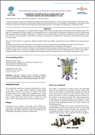
- 1. 136 International Journal of Research and Innovation (IJRI) International Journal of Research and Innovation (IJRI) GEOMETRIC OPTIMIZATION OF CRANK SHAFT FOR OPTIMUM DESIGN AND IMPROVEMENT OF LIFE Kamugari Naveen Goud1 , Baby Theresa Gudavalli2 , Godi Subba Rao3 , 1 Research Scholar, Department of Mechanical Engineering, Hyderabad Institute of Technology and Management, Hyderabad, India 2 Assistant Professor, Department of Mechanical Engineering, Hyderabad Institute of Technology and Management, Hyderabad, India 3 Professor, Department of Mechanical Engineering, Hyderabad Institute of Technology and Management, Hyderabad, India *Corresponding Author: Kamugari Naveen Goud, Research Scholar, Department of Mechanical Engineering, HyderabadInstituteOfTechnology And Management,Hyderabad,India Published: July 04, 2015 Review Type: peer reviewed Volume: II, Issue : IV Citation: Kamugari Naveen Goud, Research Scholar (2015) GEOMETRIC OPTIMIZATION OF CRANK SHAFT FOR OPTIMUM DESIGN AND IMPROVEMENT OF LIFE INTRODUCTION The crankshaft, sometimes casually abbreviated to crank, is the part of an engine which translates reciprocating linear piston motion into rotation. To convert the recip- rocating motion into rotation, the crankshaft has "crank throws" or "crankpins", additional bearing surfaces whose axis is offset from that of the crank, to which the "big ends" of the connecting rods from each cylinder attach. Design Components of a typical, four stroke cycle, DOHC pis- ton engine. (E) Exhaust camshaft, (I) Intake camshaft, (S) Spark plug, (V) Valves, (P) Piston, (R) Connecting rod, (C) Crankshaft, (W) Water jacket for coolant flow. Stress on crankshafts The shaft is subjected to various forces but generally needs to be analysed in two positions. Firstly, failure may occur at the position of maximum bending; this may be at the centre of the crank or at either end. In such a con- dition the failure is due to bending and the pressure in the cylinder is maximal. Second, the crank may fail due to twisting, so the conrod needs to be checked for shear at the position of maximal twisting. The pressure at this position is the maximal pressure, but only a fraction of maximal pressure. A crankshaft contains two or more centrally-located co- axial cylindrical ("main") journals and one or more offset cylindrical crankpin ("rod") journals. The two-plane V8 crankshaft pictured in Figure 1 has five main journals and four rod journals, each spaced 90° from its neigbors. Abstract Crankshaft is a component in an engine which converts the reciprocating motion of the piston to the rotary motion. De- sign of a crankshaft of Honda engine, it is assembled by the connecting rod and piston components in Pro engineering. The designed model of engine crankshaft is analyzed in pro engineering by using its mechanism. Piston generates the forces due to the combustion. These forces acting on the piston are analyzed by using their mechanisms with respect to crank angle. The aim of the project is to generate efficient model within low weight and good structural ability for the improvement of life. Initially da ta collection and literature survey will be done to understand methodology and selection of material. 3D model will be prepared according to the dimensions’ obtained from theoretical calculations. Analysis will be done to validate structural and thermal behavior; design modifications will be according to the obtained results to improve the structural stability, material will be removed at stress non effecting areas to reduce the weight. Analysis will be done to compare modified with existing model, conclusion will be made after comparing results 1401-1402
- 2. 137 International Journal of Research and Innovation (IJRI) The crankshaft main journals rotate in a set of supporting bearings ("main bearings"), causing the offset rod journals to rotate in a circular path around the main journal cent- ers, the diameter of which is twice the offset of the rod journals. The diameter of that path is the engine "stroke": the distance the piston moves up and down in its cylin- der. The big ends of the connecting rods ("conrods") con- tain bearings ("rod bearings") which ride on the offset rod journals. FORCES IMPOSED ON A CRANKSHAFT The obvious source of forces applied to a crankshaft is the product of combustion chamber pressure acting on the top of the piston. High-performance, normally-aspirated Spark-ignition (SI) engines can have combustion pres- sures in the 100-bar neighborhood (1450 psi), while con- temporary high-performance Compression-Ignition (CI) engines can see combustion pressures in excess of 200 bar (2900 psi). A pressure of 100 bar acting on a 4.00 inch diameter piston wil produce a force of 18,221 pounds. A pressure of 200 bar acting on a 4.00 inch diameter piston produces a force of 36,442 pounds. That level of force ex- erted onto a crankshaft rod journal produces substantial bending and torsional moments and the resulting tensile, compressive and shear stresses. CRANKSHAFT MANUFACTURING PROCESSES Many high performance crankshafts are formed by the forging process, in which a billet of suitable size is heated to the appropriate forging temperature, typically in the range of 1950 - 2250°F, and then successively pounded or pressed into the desired shape by squeezing the billet between pairs of dies under very high pressure. These die sets have the concave negative form of the desired exter- nal shape. Complex shapes and / or extreme deforma- tions often require more than one set of dies to accom- plish the shaping. Originally, two-plane V8 cranks were forged in a single plane, then the number two and four main journals were reheated and twisted 90° to move crankpins number two and three into a perpendicular plane. Later developments in forging technology allowed the forging of a 2-plane "non-twist" crank directly INTRODUCTION TO PRO/ENGINEER Pro/ENGINEER is the industry’s standard 3D mechanical design suit. It is the world’s leading CAD/CAM /CAE soft- ware, gives a broad range of integrated solutions to cover all aspects of product design and manufacturing. Much of its success can be attributed to its technology which spurs its customer’s to more quickly and consistently in- novate a new robust, parametric, feature based model, because the Pro/E technology is unmatched in this field, in all processes, in all countries, in all kind of companies along the supply chains. Pro/Engineer is also the perfect solution for the manufacturing enterprise, with associa- tive applications, robust responsiveness and web connec- tivity that make it the ideal flexible engineering solution to accelerate innovations. Pro/Engineer provides easy to use solution tailored to the needs of small, medium sized enterprises as well as large industrial corporations in all industries, consumer goods, fabrications and assembly, electrical and electronics goods, automotive, aerospace etc. DESIGN OF MULTI CYLINDER ENGINE CRANK SHAFT (DIESEL ENGINE) Number of cylinders=4 Bore diameter (D) = 85 mm Stroke length (l) = 96mm Maximum combustion pressure=2.5 N/mm2 We know that force on the piston i,e: gas load In order to find the thrust in connecting rod we should find out angle of inclination of connecting rod with line of stroke Assume that the distance (b) between the bearings 1 and 2 is equal to twice the piston diameter (D). b = 2D = 2 × 85 =170mm Due to this piston gas load (FP) acting horizontally, there will be two horizontal reactions H1and H2 at bearings 1 and 2 respectively, such that b1 = b2= 85mm Assume that the length of the main bearings to be equal, i.e., c1 = c2 = c / 2. We know that due to the weight of the flywheel acting downwards, there will be two vertical reactions V2 and V3 at Bearings 2 and 3 respectively, such that
- 3. 138 International Journal of Research and Innovation (IJRI) MODEL OF CRANK SHAFT The above image shows sketcher The above image shows crank web The above image shows crank shaft final model STRUCTURAL ANALYSIS OF CRANKSHAFT EX- ISTING MODEL MATERIAL: CARBON STEEL The above image shows imported model The above image shows meshed model The above image shows load applied
- 4. 139 International Journal of Research and Innovation (IJRI) The above image shows total deformation The above image shows stress The above image shows strain MODEL ANALYSIS OF CRANKSHAFT EXISTING MODEL THERMAL ANALYSIS OF CRANKSHAFT EXIST- ING MODEL The above image shows temperature The above image shows total heat flux
- 5. 140 International Journal of Research and Innovation (IJRI) The above image shows thermal error FATIGUE ANALYSIS OF CRANKSHAFT EXISTING MODEL The above image shows life The above image shows safety factor STRUCTURAL ANALYSIS OF CRANKSHAFT MOD- IFIED MODEL MATERIAL: CARBON STEEL The above image shows imported model The above image shows total deformation The above image shows stress
- 6. 141 International Journal of Research and Innovation (IJRI) MODEL ANALYSIS OF CRANKSHAFT MODIFIED MODEL The above image shows total deformation mode 1 THERMAL ANALYSIS OF CRANKSHAFT MODI- FIED MODEL The above image shows temperature The above image shows total heat flux RESULTS AND GRAPHS STRUCTURAL ANALYSIS GRAPHS The above image shows displacement graph The above image shows stress graph THERMAL ANALYSIS The above image shows thermal error FATIGUE ANALYSIS The above image shows Safety factor
- 7. 142 International Journal of Research and Innovation (IJRI) STRUCTURAL ANALYSIS Existing model Modified model carbon steel nickel chromium molybdenum steel carbon steel nickel chromium molybdenum steel Total defor- mation 0.00094443 0.0009807 0.00080902 0.0007657 Stress 3.2358 3.3025 2.5753 2.6323 Strain 1.253e-5 1.6546e-5 1.2112e-5 1.3193e-5 THERMAL ANALYSIS Existing model Modified model carbon steel nickel chromium molybdenum steel carbon steel nickel chromium molybdenum steel Temperature 150 150 150 150 Total heat flux 2.3442 0.87371 2.5669 1.0331 Thermal error 5.3054e5 1.0861e5 8.766e5 1.942e5 FATIGUE ANALYSIS Existing model Modified model carbon steel nickel chromium molybdenum steel carbon steel nickel chromium molybdenum steel LIFE 3.65e9 3.65e9 3.65e9 3.65e9 Damage 0.27397 0.27397 0.27397 0.27397 Safety factor 3.3357 3.2683 4.1911 4.1005 Biaxiality indication 0.99899 0.99889 0.9993 0.99819 Alternating stress 32.358 33.025 25.753 26.323 CONCLUSION This project works deals with “GEOMETRIC OPTIMIZA- TION OF CRANK SHAFT FOR OPTIMUM DESIGN AND IMPROVEMENT OF LIFE” Initially literature survey and data collection was done to understand methodology. Crank shaft parameters are calculated using empirical formals for 6 cylinder engine. 3d model is prepared according to the obtained valve from calculation, Static, fatigue and dynamic analysis is done on crank- shaft using low carbon steel. Same as been done using steel nickel chromium molybdenum steel material and to find out the failure locations and to evaluate results. Geometric modifications are done on crank shaft model to reduce stress concentration by implementing stress reliv- ing holes on web. As per the Static, fatigue and dynamic analysis results, existing model is up to the mark only. Implementation of nickel chromium molybdenum steel material will increase life by 2%, while Appling stress reliving holes, life will be increased by 17.8%. Also material is removed from the crank web. So better to use modified model with nickel chromium molybdenum steel material. This project concludes that modified model with nickel chromium molybdenum steel material increases the life and also weight will be reduced up to 15% which interns increases the mechanical efficiency REFERENCES 1. Dynamic Stress Analysis of a Multi cylinder Two- stage Compressor Crankshaft 2. DESIGN AND ANALYSIS OF CRANKSHAFT FOR SIN- GLE CYLINDER 4-STROKE DEISEL ENGINE 3. Crankshaft Design and Optimization- A Review 4. Theoretical and Experimental Analysis of Torsional and Bending Effect on Four Cylinders Engine Crank- shafts by Using Finite Element Approach 5. Fatigue Strength and Residual Stress Analysis of Deep Rolled Crankshafts 6. Finite Element Analysis of 4-Cylinder Diesel Crank- shaft 7. Crankshaft Strength Analysis Using Finite Element Method 8. Concept and manufacture of a crankshaft production tool 9. Crankshaft, Flexible tool, Finite element method, Ex- perimentation. 10. Elastic Multi Body Simulation of a Multi-Cylinder En- gine author Kamugari –Naveen Goud Research Scholar, Department of Mechanical Engineering, Hyderabadinstitute of Technology and Management, Hyderabad,India Baby Theresa Gudavalli, Assistant Professor , Department of Mechanical Engineering, Hyderabadinstitute of Technology and Management, Hyderabad,India Godi Subba Rao, Professor, Department Of Mechanical Engineering, Hyderabadinstituteof Technology And Management, Hyderabad,India