SlideShare a Scribd company logo
1 of 21
Download to read offline
Lab: Engine Disassembly & Assembly
Jet Engine
Lab: Engine Disassembly & Assembly
Task1: The task is about the development of Aero Engines
(Turbojet Engine; Turbofan Engine; Turboshaft Engine;
Turboprop Engine).
Answer:
The development of Aero Engines
Introduction
An aero engine is a component of the propulsion system for an aircraft that generates
mechanical power. Aero engines are almost always either lightweight piston engines or gas
turbines, except for small multicopter UAVs which are almost always electric aircraft. There
are many kinds of aero engines. Here, I have to discuss about develop of Aero Engines like
Turbojet, Turbofan, Turboshaft and Turboprop Engine.
The question asks about the development of Aero Engines that means all engines are Jet
Engines which are also called Gas Turbine Engines.
Jet engines move the airplane forward with a great force that is produced by a tremendous
thrust and causes the plane to fly very fast. So, the main principal is Newton’s third law of
motion. Sir Isaac Newton in the 18th century was the first to theorize that a rearward-channeled
explosion could propel a machine forward at a great rate of speed. This theory was based on
his third law of motion. As the hot air blasts backwards through the nozzle the plane moves
forward.
Frank Whittle, a British pilot, who designed and patented the first turbo jet engine in 1930.
The Whittle engine first flew successfully in May, 1941. This engine featured a multistage
compressor, and a combustion chamber, a single stage turbine and a nozzle.
Jet Engine parts:
Figure1 Jet Engine parts
Lab: Engine Disassembly & Assembly
All jet engines, which are also called gas turbines, work on the same principle.
The engine sucks air in at the front with a fan. A compressor raises the pressure of the air. The
compressor is made with many blades attached to a shaft. The blades spin at high speed and
compress or squeeze the air. The compressed air is then sprayed with fuel and an electric spark
lights the mixture. The burning gases expand and blast out through the nozzle, at the back of
the engine. As the jets of gas shoot backward, the engine and the aircraft are thrust forward. As
the hot air is going to the nozzle, it passes through another group of blades called the turbine.
The turbine is attached to the same shaft as the compressor. Spinning the turbine causes the
compressor to spin.
While each of the engines are different, But, they share some parts in common. These are
discussed below
Fan: The fan is the first component in a turbofan.
Figure1.1 Fan (red color)
The large spinning fan sucks in large quantities of air. Most blades of the fan are made of
titanium. It then speeds this air up and splits it into two parts. One part continues through the
"core" or center of the engine, where it is acted upon by the other engine components.
The second part "bypasses" the core of the engine. It goes through a duct that surrounds the
core to the back of the engine where it produces much of the force that propels the airplane
forward. This cooler air helps to quiet the engine as well as adding thrust to the engine.
Lab: Engine Disassembly & Assembly
Inlet: All turbine engines have an inlet to bring free stream air into the engine. The
inlet sits upstream of the compressor and, while the inlet does no work on the flow, inlet
performance has a strong influence on engine net thrust. As shown in the figures above, inlets
come in a variety of shapes and sizes with the specifics usually dictated by the speed of the
aircraft.
Figure1.2 Inlet (Intake in British)
 Subsonic inlets: For aircraft that cannot go faster than the speed of sound, like large
airliners, a simple, straight, short inlet works quite well. On a typical subsonic inlet, the
surface of the inlet from outside to inside is a continuous smooth curve with some
thickness from inside to outside. The most upstream portion of the inlet is called
the highlight, or the inlet lip. A subsonic aircraft has an inlet with a relatively thick lip.
 Supersonic inlets: For a supersonic aircraft, the inlet must slow the flow down to
subsonic speeds before the air reaches the compressor because of shock waves. Some
supersonic inlets, like the one at the upper right, use a central cone to shock the flow
down to subsonic speeds. Other inlets, like the one shown at the lower left, use flat
hinged plates to generate the compression shocks, with the resulting inlet geometry
having a rectangular cross section. This variable geometry inlet is used on the F-14 and
F-15 fighter aircraft.
 Hypersonic inlets: Inlets for hypersonic aircraft present the ultimate design challenge.
For ramjet-powered aircraft, the inlet must bring the high speed external flow down to
subsonic conditions in the burner. High stagnation temperatures are present in this
speed regime and variable geometry may not be an option for the inlet designer because
of possible flow leaks through the hinges. For scramjet-powered aircraft, the heat
environment is even worse because the flight Mach number is higher than that for a
ramjet-powered aircraft. Scramjet inlets are highly integrated with the fuselage of the
aircraft. On the X-43A, the inlet includes the entire lower surface of the aircraft forward
Lab: Engine Disassembly & Assembly
of the cowl lip. Thick, hot boundary layers are usually present on the compression
surfaces of hypersonic inlets. The flow exiting a scramjet inlet must remain supersonic.
 Inlet efficiency: An inlet must operate efficiently over the entire flight envelope of the
aircraft. At very low aircraft speeds, or when just sitting on the runway, free stream air
is pulled into the engine by the compressor. At high speeds, a good inlet will allow the
aircraft to maneuver to high angles of attack and sideslip without disrupting flow to the
compressor. Because the inlet is so important to overall aircraft operation, it is usually
designed and tested by the airframe company, not the engine manufacturer. But because
inlet operation is so important to engine performance, all engine manufacturers also
employ inlet aerodynamicists. Different airframers use different indices, but all of the
indices are based on ratios of the local variation of pressure to the average pressure at
the compressor face.
 hypersonic inlets are normally characterized by their kinetic energy efficiency. If the
airflow demanded by the engine is much less than the airflow that can be captured by
the inlet, then the difference in airflow is spilled around the inlet. The airflow mis-
match can produce spillage drag on the aircraft.
Compressor: The compressor is the first component in the engine core. The compressor is
made up of fans with many blades and attached to a shaft. The compressor squeezes the air that
enters it into progressively smaller areas, resulting in an increase in the air pressure. This results
in an increase in the energy potential of the air. The squashed air is forced into the combustion
chamber.
Figure1.3 Compressor
Lab: Engine Disassembly & Assembly
As shown in the above figure, there are two main types of
compressors: axial and centrifugal.
 In the picture, the compressor on the left is called an axial compressor because the flow
through the compressor travels parallel to the axis of rotation. Modern
large turbojet and turbofan engines usually use axial compressors.
 The compressor on the right is called a centrifugal compressor because the flow
through this compressor is turned perpendicular to the axis of rotation. Centrifugal
compressors, which were used in the first jet engines, are still used on small turbojets
and turboshaft engines and as pumps on rocket engines.
Combustor: In the combustor the air is mixed with fuel and then ignited. There are as many
as 20 nozzles to spray fuel into the airstream. The mixture of air and fuel catches fire. This
provides a high temperature, high-energy airflow. The fuel burns with the oxygen in the
compressed air, producing hot expanding gases. The inside of the combustor is often made of
ceramic materials to provide a heat-resistant chamber. The heat can reach 2700.
Figure1.4 Combustor-Burner
There are three main types of combustors, and all three designs are found in modern gas
turbines:
 The burner at the left is an annular combustor with the liner sitting inside the outer
casing which has been peeled open in the drawing. Many modern burners have an
annular design.
 The burner in the middle is an older can or tubular design. The photo at the top left
shows some actual burner cans. Each can have both a liner and a casing, and the cans
are arranged around the central shaft.
Lab: Engine Disassembly & Assembly
 A compromise design is shown at the right. This is a can-annular design, in
which the casing is annular and the liner is can-shaped. The advantage to the can-
annular design is that the individual cans are more easily designed, tested, and serviced.
Turbine: The high-energy airflow coming out of the combustor goes into the turbine, causing
the turbine blades to rotate. The turbines are linked by a shaft to turn the blades in the
compressor and to spin the intake fan at the front. This rotation takes some energy from the
high-energy flow that is used to drive the fan and the compressor. The gases produced in the
combustion chamber move through the turbine and spin its blades. The turbines of the jet spin
around thousands of times. They are fixed on shafts which have several sets of ball-bearing in
between them.
Figure1.5 Turbine
Depending on the engine type, there may be multiple turbine stages present in the engine.
 Turbofan and turboprop engines usually employ a separate turbine and shaft to power
the fan and gear box respectively. Such an arrangement is termed a two spool engine.
The power turbine shown on the upper left of the figure is for a two spool, turbofan
engine.
 For some high performance engines, an additional turbine and shaft is present to power
separate parts of the compressor. This arrangement produces a three spool engine.
Lab: Engine Disassembly & Assembly
Nozzle: The nozzle is the exhaust duct of the engine. This is the engine part which actually
produces the thrust for the plane. The energy depleted airflow that passed the turbine, in
addition to the colder air that bypassed the engine core, produces a force when exiting the
nozzle that acts to propel the engine, and therefore the airplane, forward. The combination of
the hot air and cold air are expelled and produce an exhaust, which causes a forward thrust.
The nozzle may be preceded by a mixer, which combines the high temperature air coming from
the engine core with the lower temperature air that was bypassed in the fan. The mixer helps
to make the engine quieter.
Figure1.6 Nozzle
As shown above, nozzles come in a variety of shapes and sizes depending on the mission of
the aircraft.
 Simple turbojets, and turboprops, often have a fixed geometry convergent nozzle as
shown on the left of the figure.
 Turbofan engines often employ a co-annular nozzle as shown at the top left. The core
flow exits the center nozzle while the fan flow exits the annular nozzle. Mixing of the
two flows provides some thrust enhancement and these nozzles also tend to be quieter
than convergent nozzles.
 Afterburning turbojets and turbofans require a variable geometry convergent-divergent
- CD nozzle as shown on the left. In this nozzle, the flow first converges down to
the minimum area or throat, then is expanded through the divergent section to the exit
at the right. The flow is subsonic upstream of the throat, but supersonic downstream of
the throat.
All of the nozzles we have discussed thus far are round tubes. Recently, however, engineers
have been experimenting with nozzles with rectangular exits. This allows the exhaust flow to
Lab: Engine Disassembly & Assembly
be easily deflected, or vectored, as shown in the middle of the figure. Changing the
direction of the thrust with the nozzle makes the aircraft much more maneuverable.
Turbojet Engine
Figure2 Turbojet Engine
The turbojet is an air breathing jet engine, typically used in aircraft. It consists of a gas
turbine with a propelling nozzle. The gas turbine has an air inlet, a compressor, a combustion
chamber, and a turbine (that drives the compressor). Two engineers, Frank Whittle in
the United Kingdom and Hans von Ohain in Germany, developed the concept independently
into practical engines during the late 1930s.
A turbojet is a type of gas turbine engine that was originally developed for military fighters
during World War II. When turbojets were introduced, the top speed of fighter aircraft
equipped with them was at least 100 miles per hour faster than competing piston-driven aircraft.
In the years after the war, the drawbacks of the turbojet gradually became apparent. Below
about Mach 2, turbojets are very fuel inefficient and create tremendous amounts of noise. Early
designs also respond very slowly to power changes, a fact that killed many experienced pilots
when they attempted the transition to jets. These drawbacks eventually led to the downfall of
the pure turbojet, and only a handful of types are still in production. The last airliner that used
turbojets was the Concorde, whose Mach 2 airspeed permitted the engine to be highly efficient.
Early Development and Designs: Early German turbojets had severe limitations on the
amount of running they could do due to the lack of suitable high temperature materials for the
turbines. British engines such as the Rolls-Royce Welland used better materials giving
improved durability. The Welland was type-certified for 80 hours initially, later extended to
150 hours between overhauls, as a result of an extended 500-hour run being achieved in
Lab: Engine Disassembly & Assembly
tests. Despite their high maintenance, some of the early jet fighters are still
operational with their original engines.
General Electric in the United States was in a good position to enter the jet engine business due
to its experience with the high-temperature materials used in their turbosuperchargers during
World War II.
Water injection was a common method used to increase thrust, usually during takeoff, in early
turbojets that were thrust-limited by their allowable turbine entry temperature. The water
increased thrust at the temperature limit, but prevented complete combustion, often leaving a
very visible smoke trail.
Allowable turbine entry temperatures have increased steadily over time both with the
introduction of superior alloys and coatings, and with the introduction and progressive
effectiveness of blade cooling designs. On early engines, the turbine temperature limit had to
be monitored, and avoided, by the pilot, typically during starting and at maximum thrust
settings. Automatic temperature limiting was introduced to reduce pilot workload and reduce
the likelihood of turbine damage due to over-temperature.
Design & Development:
Air intake/ Inlet: An intake, or tube, is needed in front of the compressor to help direct the
incoming air smoothly into the moving compressor blades. Older engines had stationary vanes
in front of the moving blades. These vanes also helped to direct the air onto the blades. The air
flowing into a turbojet engine is always subsonic, regardless of the speed of the aircraft itself.
The intake has to supply air to the engine with an acceptably small variation in pressure (known
as distortion) and having lost as little energy as possible on the way (known as pressure
recovery). The ram pressure rise in the intake is the inlets contribution to the propulsion
system overall pressure ratio and thermal efficiency.
The intake gains prominence at high speeds when it transmits more thrust to the airframe than
the engine does.
Compressor: The compressor is driven by the turbine. It rotates at high speed,
adding energy to the airflow and at the same time squeezing (compressing) it into a smaller
space. Compressing the air increases its pressure and temperature. The smaller the compressor,
the faster it turns. At the large end of the range, the GE-90-115 fan rotates at about 2,500 RPM,
while a small helicopter engine compressor rotates around 50,000 RPM.
Turbojets supply bleed air from the compressor to the aircraft for the environmental control
system, anti-icing, and fuel tank pressurization, for example. The engine itself needs air at
various pressures and flow rates to keep it running. This air comes from the compressor, and
without it, the turbines would overheat, the lubricating oil would leak from the bearing cavities,
the rotor thrust bearings would skid or be overloaded, and ice would form on the nose cone.
The air from the compressor, called secondary air, is used for turbine cooling, bearing cavity
Lab: Engine Disassembly & Assembly
sealing, anti-icing, and ensuring that the rotor axial load on its thrust bearing will not
wear it out prematurely. Supplying bleed air to the aircraft decreases the efficiency of the
engine because it has been compressed, but then does not contribute to producing thrust. Bleed
air for aircraft services is no longer needed on the turbofan-powered Boeing 787.
Compressor types used in turbojets were typically axial or centrifugal. Early turbojet
compressors had low pressure ratios up to about 5:1. Aerodynamic improvements including
splitting the compressor into two separately rotating parts, incorporating variable blade angles
for entry guide vanes and stators, and bleeding air from the compressor enabled later turbojets
to have overall pressure ratios of 15:1 or more. For comparison, modern civil turbofan engines
have overall pressure ratios of 44:1 or more. After leaving the compressor, the air enters the
combustion chamber.
Combustion chamber: The burning process in the combustor is significantly different from
that in a piston engine. In a piston engine, the burning gases are confined to a small volume,
and as the fuel burns, the pressure increases. In a turbojet, the air and fuel mixture burn in the
combustor and pass through to the turbine in a continuous flowing process with no pressure
build-up. Instead, a small pressure loss occurs in the combustor.
The fuel-air mixture can only burn in slow-moving air, so an area of reverse flow is maintained
by the fuel nozzles for the approximately stoichiometric burning in the primary zone. Further
compressor air is introduced which completes the combustion process and reduces the
temperature of the combustion products to a level which the turbine can accept. Less than 25%
of the air is typically used for combustion, as an overall lean mixture is required to keep within
the turbine temperature limits.
Turbine: Hot gases leaving the combustor expand through the turbine. Typical materials for
turbines include inconel and Nimonic. The hottest turbine vanes and blades in an engine have
internal cooling passages. Air from the compressor is passed through these to keep the metal
temperature within limits. The remaining stages do not need cooling.
In the first stage, the turbine is largely an impulse turbine (similar to a pelton wheel) and rotates
because of the impact of the hot gas stream. Later stages are convergent ducts that accelerate
the gas. Energy is transferred into the shaft through momentum exchange in the opposite way
to energy transfer in the compressor. The power developed by the turbine drives the compressor
and accessories, like fuel, oil, and hydraulic pumps that are driven by the accessory gearbox.
Nozzle: After the turbine, the gases expand through the exhaust nozzle producing a high
velocity jet. In a convergent nozzle, the ducting narrows progressively to a throat. The nozzle
pressure ratio on a turbojet is high enough at higher thrust settings to cause the nozzle to choke.
If, however, a convergent-divergent de Laval nozzle is fitted, the divergent (increasing flow
area) section allows the gases to reach supersonic velocity within the divergent section.
Additional thrust is generated by the higher resulting exhaust velocity.
Lab: Engine Disassembly & Assembly
Thrust augmentation: Thrust was most commonly increased in turbojets injection or
afterburning. Some engines used both at the same time.
Afterburner: An afterburner or "reheat jetpipe" is a combustion chamber added to reheat the
turbine exhaust gases. The fuel consumption is very high, typically four times that of the main
engine. Afterburners are used almost exclusively on supersonic aircraft, most being military
aircraft. Two supersonic airliners, Concorde and the Tu-144, also used afterburners as
does Scaled Composites White Knight, a carrier aircraft for the experimental Space Ship
One suborbital spacecraft.
Net thrust: If the speed of the jet is equal to sonic velocity the nozzle is said to be choked. If
the nozzle is choked the pressure at the nozzle exit plane is greater than atmospheric pressure,
and extra terms must be added to the above equation to account for the pressure thrust.
Figure2.1 Turbojet Thrust
The rate of flow of fuel entering the engine is very small compared with the rate of flow of
air. If the contribution of fuel to the nozzle gross thrust is ignored, the net thrust is:
The speed of the jet Ve must exceed the true airspeed of the aircraft V0 if there is to be a net
forward thrust on the airframe. The speed Ve can be calculated thermodynamically based
on adiabatic expansion.
Lab: Engine Disassembly & Assembly
Cycle improvements: The operation of a turbojet is modelled approximately by the Brayton
cycle.
Figure2.2 The idealized Brayton cycle
Where,
P = pressure,
V = volume,
T = temperature,
S = entropy, and
Q = the heat added to or rejected by the system
The efficiency of a gas turbine is increased by raising the overall pressure ratio, requiring
higher-temperature compressor materials, and raising the turbine entry temperature, requiring
better turbine materials and/or improved vane/blade cooling. It is also increased by reducing
the losses as the flow progresses from the intake to the propelling nozzle. These losses are
quantified by compressor and turbine efficiencies and ducting pressure losses. When used in a
turbojet application, where the output from the gas turbine is used in a propelling nozzle, raising
the turbine temperature increases the jet velocity. At normal subsonic speeds this reduces the
propulsive efficiency, giving an overall loss, as reflected by the higher fuel consumption, or
SFC.
However, for supersonic aircraft this can be beneficial, and is part of the reason why the
Concorde employed turbojets. Turbojet systems are complex systems therefore to secure
optimal function of such system, there is a call for the newer models being developed to
advance its control systems to implement the newest knowledge from the areas of automation.
Lab: Engine Disassembly & Assembly
Turbofan Engine
Figure3 Schematic diagram of a high-bypass turbofan engine
Principles: A turbofan engine has a large fan at the front, which sucks in air. Most of the air
flows around the outside of the engine, making it quieter and giving more thrust at low speeds.
Most of today's airliners are powered by turbofans. In a turbojet all the air entering the intake
passes through the gas generator, which is composed of the compressor, combustion chamber,
and turbine. In a turbofan engine only a portion of the incoming air goes into the combustion
chamber. The remainder passes through a fan, or low-pressure compressor, and is ejected
directly as a "cold" jet or mixed with the gas-generator exhaust to produce a "hot" jet. The
objective of this sort of bypass system is to increase thrust without increasing fuel consumption.
It achieves this by increasing the total air-mass flow and reducing the velocity within the same
total energy supply.
Bypass ratio: The bypass ratio (BPR) of a turbofan engine is the ratio between the mass flow
rate of the bypass stream to the mass flow rate entering the core. A 10:1 bypass ratio, for
example, means that 10 kg of air passes through the bypass duct for every 1 kg of air passing
through the core.
Efficiency: Since the efficiency of propulsion is a function of the relative airspeed of the
exhaust to the surrounding air, propellers are most efficient for low speed, pure jets for high
speeds, and ducted fans in the middle. Turbofans are thus the most efficient engines in the
range of speeds from about 500 to 1,000 km/h (310 to 620 mph), the speed at which most
commercial aircraft operate. Turbofans retain an efficiency edge over pure jets at
low supersonic speeds up to roughly Mach 1.6 (1,960.1 km/h; 1,217.9 mph).
Lab: Engine Disassembly & Assembly
Thrust: The thrust (FN) generated by a turbofan depends on the effective exhaust
velocity of the total exhaust, as with any jet engine, but because two exhaust jets are present
the thrust equation can be expanded as:
Figure3.1 Turbofan Thrust
Nozzles: The cold duct and core duct's nozzle systems are relatively complex due to there being
two exhaust flows.
In high bypass engines the fan is generally situated in a short duct near the front of the engine
and typically has a convergent cold nozzle, with the tail of the duct forming a low pressure
ratio nozzle that under normal conditions will choke creating supersonic flow patterns around
the core.
The core nozzle is more conventional, but generates less of the thrust, and depending on design
choices, such as noise considerations, may conceivably not choke.
In low bypass engines the two flows may combine within the ducts, and share a common
nozzle, which can be fitted with afterburner.
Recent development:
Aerodynamic modelling: Aerodynami is a mix of subsonic, transonic and supersonic airflow
on a single fan/gas compressor blade in a modern turbofan. The airflow past the blades has to
be maintained within close angular limits to keep the air flowing against an increasing pressure.
Otherwise the air will come back out of the intake.
Lab: Engine Disassembly & Assembly
Blade technology: A 100 g turbine blade is subjected to 1,700 °C/3100 °F, at 17
bars/250 Psi and a centrifugal force of 40 kN/ 9,000 lbf, well above the point of plastic
deformation and even above the melting point. Exotic alloys, sophisticated air
cooling schemes and special mechanical design are needed to keep the physical stresses within
the strength of the material. Rotating seals must withstand harsh conditions for 10 years, 20,000
missions and rotating at 10–20,000 rpm.
Fan blades: Fan blades have been growing as jet engines have been getting bigger: each fan
blade carries the equivalent of nine double-decker buses and swallows the volume of a squash
court every second. Advances in computational fluid dynamics (CFD) modelling have
permitted complex, 3D curved shapes with very wide chord, keeping the fan capabilities while
minimizing the blade count to lower costs. Coincidentally, the bypass ratio grew to achieve
higher propulsive efficiency and the fan diameter increased.
Cycle improvements: According to simple theory, if the ratio of turbine rotor inlet
temperature/(HP) compressor delivery temperature is maintained, the HP turbine throat area
can be retained. However, this assumes that cycle improvements are obtained, while retaining
the datum (HP) compressor exit flow function (non-dimensional flow). In practice, changes to
the non-dimensional speed of the (HP) compressor and cooling bleed extraction would
probably make this assumption invalid, making some adjustment to HP turbine throat area
unavoidable. This means the HP turbine nozzle guide vanes would have to be different from
the original. In all probability, the downstream LP turbine nozzle guide vanes would have to
be changed anyway.
Thrust growth: Thrust growth is obtained by increasing core power. There are two basic
routes available:
 hot route: increase HP turbine rotor inlet temperature
 cold route: increase core mass flow
Both routes require an increase in the combustor fuel flow and, therefore, the heat energy added
to the core stream. The hot route may require changes in turbine blade/vane materials and/or
better blade/vane cooling. The cold route can be obtained by one of the following:
 adding T-stages to the LP/IP compression
 adding a zero-stage to the HP compression
 improving the compression process, without adding stages.
 all of which increase both overall pressure ratio and core airflow.
Future progress: Engine cores are shrinking as they are operating at higher pressure ratios and
becoming more efficient, and become smaller compared to the fan as bypass ratios increase.
Blade tip clearances are harder to maintain at the exit of the high-pressure compressor where
blades are 0.5 in (13 mm) high or less, backbone bending further affects clearance control as
the core is proportionately longer and thinner and the fan to low-pressure turbine driveshaft is
in constrained space within the core.
Lab: Engine Disassembly & Assembly
Turboprop Engine
Figure4 Schematic diagram showing the operation of a turboprop engine
Principles: A turboprop engine is a jet engine attached to a propeller. The turbine at the back
is turned by the hot gases, and this turns a shaft that drives the propeller. Some small airliners
and transport aircraft are powered by turboprops.
Like the turbojet, the turboprop engine consists of a compressor, combustion chamber, and
turbine, the air and gas pressure is used to run the turbine, which then creates power to drive
the compressor. Compared with a turbojet engine, the turboprop has better propulsion
efficiency at flight speeds below about 500 miles per hour. Modern turboprop engines are
equipped with propellers that have a smaller diameter but a larger number of blades for efficient
operation at much higher flight speeds. To accommodate the higher flight speeds, the blades
are scimitar-shaped with swept-back leading edges at the blade tips. Engines featuring such
propellers are called propfans.
Turboprop Thrust:
Figure4.1 Turboprop Thrust
Lab: Engine Disassembly & Assembly
Technological aspects:
Figure4.2 Propulsive efficiency comparison for various gas turbine engine
configurations.
Exhaust thrust in a turboprop is sacrificed in favour of shaft power, which is obtained by
extracting additional power (up to that necessary to drive the compressor) from turbine
expansion. Owing to the additional expansion in the turbine system, the residual energy in the
exhaust jet is low. Consequently, the exhaust jet typically produces around or less than 10% of
the total thrust. A higher proportion of the thrust comes from the propeller at low speeds and
less at higher speeds.
Propellers lose efficiency as aircraft speed increases, so turboprops are normally not used on
high-speed aircraft above Mach 0.6-0.7. However, propfan engines, which are very similar to
turboprop engines, can cruise at flight speeds approaching Mach 0.75. To increase propeller
efficiency, a mechanism can be used to alter their pitch relative to the airspeed. A variable-
pitch propeller, also called a controllable-pitch propeller, can also be used to generate negative
thrust while decelerating on the runway. Additionally, in the event of an engine failure, the
pitch can be adjusted to a vaning pitch (called feathering), thus minimizing the drag of the non-
functioning propeller.
Uses: Turboprop engines are generally used on small subsonic aircraft, but the Tupolev Tu-
114 can reach 470 kt (870 km/h, 541 mph). Large military and civil aircraft, such as
the Lockheed L-188 Electra and the Tupolev Tu-95, have also used turboprop power.
The Airbus A400M is powered by four Europrop TP400 engines, which are the third most
powerful turboprop engines ever produced, after the eleven megawatt-output Kuznetsov NK-
12 and 10.4 MW-output Progress D-27
Reliability: Between 2012 and 2016, the ATSB observed 417 events with turboprop aircraft,
83 per year, over 1.4 million flight hours: 2.2 per 10,000 hours. Three were “high risk”
involving engine malfunction and unplanned landing in single-engine Cessna 208 Caravans,
four “medium risk” and 96% “low risk”. Two occurrences resulted in minor injuries due to
engine malfunction and terrain collision in agricultural aircraft and five accidents involved
aerial work: four in agriculture and one in an air ambulance.
Lab: Engine Disassembly & Assembly
Turboshaft Engine
A turboshaft engine is a form of gas turbine that is optimized to produce shaft power rather
than jet thrust.
In concept, turboshaft engines are very similar to turbojets, with additional turbine expansion
to extract heat energy from the exhaust and convert it into output shaft power. They are even
more similar to turboprops, with only minor differences, and a single engine is often sold in
both forms.
Turboshaft engines are commonly used in applications that require a sustained high power
output, high reliability, small size, and light weight. These include helicopters, auxiliary power
units, boats and ships, tanks, hovercraft, and stationary equipment.
Figure5 Schematic diagram showing the operation of a simplified turboshaft engine.
The compressor spool is shown in green and the free / power spool is in purple.
Overview: A turboshaft engine may be made up of two major parts assemblies: the 'gas
generator' and the 'power section'. The gas generator consists of the compressor, combustion
chambers with ignitors and fuel nozzles, and one or more stages of turbine. The power section
consists of additional stages of turbines, a reduction system, and the shaft output. The gas
generator creates the hot expanding gases to drive the power section. Depending on the design,
the engine accessories may be driven either by the gas generator or by the power section.
Lab: Engine Disassembly & Assembly
In most designs, the gas generator and power section are mechanically separate so
they can each rotate at different speeds appropriate for the conditions, referred to as a 'free
power turbine'. A free power turbine can be an extremely useful design feature for vehicles, as
it allows the design to forgo the weight and cost of complex multiple-
ratio transmissions and clutches.
The general layout of a turboshaft is similar to that of a turboprop. The main difference is a
turboprop is structurally designed to support the loads created by a rotating propeller, as the
propeller is not attached to anything but the engine itself. In contrast, turboshaft engines usually
drive a transmission which is not structurally attached to the engine. The transmission is
attached to the vehicle structure and supports the loads created instead of the engine. In
practice, though, many of the same engines are built in both turboprop and turboshaft versions,
with only minor differences.
An unusual example of the turboshaft principle is the Pratt & Whitney F135-PW-
600 turbofan engine for the STOVL F-35B – in conventional mode it operates as a turbofan,
but when powering the LiftFan, it switches partially to turboshaft mode to send
29,000 horsepower forward through a shaft and partially to turbofan mode to continue to send
thrust to the main engine's fan and rear nozzle.
Large helicopters use two or three turboshaft engines for redundancy. The Mil Mi-26 uses
two Lotarev D-136 at 11,400 hp each, while the Sikorsky CH-53E Super Stallion uses
three General Electric T64 at 4,380 hp each.
Early turboshaft engines were adaptations of turboprop engines, delivering power through a
shaft driven directly from the gas generator shafts, via a reduction gearbox. Examples of direct-
drive turboshafts include marinised or industrial Rolls-Royce Dartengines.
Principles: This is another form of gas-turbine engine that operates much like a turboprop
system. It does not drive a propeller. Instead, it provides power for a helicopter rotor. The
turboshaft engine is designed so that the speed of the helicopter rotor is independent of the
rotating speed of the gas generator. This permits the rotor speed to be kept constant even when
the speed of the generator is varied to modulate the amount of power produced.
Turboshaft takeaway:
 Pros:
 Much higher power-to-weight ratio than piston engines
 Typically, smaller than piston engines
 Cons:
 Loud
 Gear systems connected to the shaft can be complex and break down
Lab: Engine Disassembly & Assembly
References
[1] https://www.grc.nasa.gov/www/k-12/airplane/aturbj.html
[2] https://www.grc.nasa.gov/www/k-12/airplane/aturbf.html
[3] https://www.grc.nasa.gov/www/k-12/airplane/aturbp.html
[4] https://www.grc.nasa.gov/www/k-12/UEET/StudentSite/engines.html
[5] https://www.grc.nasa.gov/www/k-12/airplane/trbtyp.html
[6] https://www.grc.nasa.gov/www/k-12/Missions/Jim/Project2_ans.htm
**************END**************

More Related Content

What's hot

Centrifugal compressor: Casing and inlet. Impellers
Centrifugal compressor: Casing and inlet. ImpellersCentrifugal compressor: Casing and inlet. Impellers
Centrifugal compressor: Casing and inlet. Impellers
YashChanne2
 

What's hot (20)

Turboprop
TurbopropTurboprop
Turboprop
 
Fundamentals of jet propulsion ppt
Fundamentals of jet propulsion pptFundamentals of jet propulsion ppt
Fundamentals of jet propulsion ppt
 
air standard, fuel air and actual cycles
air standard, fuel air and actual cyclesair standard, fuel air and actual cycles
air standard, fuel air and actual cycles
 
How Gas Turbines Work
How Gas Turbines WorkHow Gas Turbines Work
How Gas Turbines Work
 
JET ENGINE PPT BY SANDEEP YADAV
JET ENGINE PPT BY SANDEEP YADAVJET ENGINE PPT BY SANDEEP YADAV
JET ENGINE PPT BY SANDEEP YADAV
 
Gas turbine engine
Gas turbine engineGas turbine engine
Gas turbine engine
 
Combustion chambers
Combustion chambersCombustion chambers
Combustion chambers
 
Performance testing of IC engine
Performance testing of IC enginePerformance testing of IC engine
Performance testing of IC engine
 
GAS TURBINE
GAS TURBINEGAS TURBINE
GAS TURBINE
 
Gas turbines
Gas turbinesGas turbines
Gas turbines
 
Method of supercharging
Method of superchargingMethod of supercharging
Method of supercharging
 
i c engines ppt.pptx
i c engines ppt.pptxi c engines ppt.pptx
i c engines ppt.pptx
 
Gas turbines working ppt
Gas turbines working pptGas turbines working ppt
Gas turbines working ppt
 
Gas turbines
Gas turbinesGas turbines
Gas turbines
 
Steam turbine Working
Steam turbine WorkingSteam turbine Working
Steam turbine Working
 
Gas turbine
Gas turbineGas turbine
Gas turbine
 
Turbojet
TurbojetTurbojet
Turbojet
 
Centrifugal compressor: Casing and inlet. Impellers
Centrifugal compressor: Casing and inlet. ImpellersCentrifugal compressor: Casing and inlet. Impellers
Centrifugal compressor: Casing and inlet. Impellers
 
Combustion in si engine
Combustion in si engineCombustion in si engine
Combustion in si engine
 
. Gas turbine presentation (2)
. Gas turbine presentation (2). Gas turbine presentation (2)
. Gas turbine presentation (2)
 

Similar to Gas Turbine Engines-Shenyang Aerospace University

Turbojet- Sumit Prajapati (07ME105)
Turbojet- Sumit Prajapati (07ME105)Turbojet- Sumit Prajapati (07ME105)
Turbojet- Sumit Prajapati (07ME105)
Sumit Prajapati
 
GAS TURBINE ENGINE ADLEY AND WAHYU.pptx
GAS TURBINE ENGINE ADLEY AND WAHYU.pptxGAS TURBINE ENGINE ADLEY AND WAHYU.pptx
GAS TURBINE ENGINE ADLEY AND WAHYU.pptx
Deyo4
 
Seminar report
Seminar reportSeminar report
Seminar report
sonu5612
 
Turbine engine 1
Turbine engine 1Turbine engine 1
Turbine engine 1
Zaib Amjad
 

Similar to Gas Turbine Engines-Shenyang Aerospace University (20)

GAS_TURBINE_ENGINE_PROJECT_FOR_DIPLOMA
GAS_TURBINE_ENGINE_PROJECT_FOR_DIPLOMAGAS_TURBINE_ENGINE_PROJECT_FOR_DIPLOMA
GAS_TURBINE_ENGINE_PROJECT_FOR_DIPLOMA
 
PROJECT_GAS_TURBINE_ENGINE
PROJECT_GAS_TURBINE_ENGINEPROJECT_GAS_TURBINE_ENGINE
PROJECT_GAS_TURBINE_ENGINE
 
jet engine.pdf
jet engine.pdfjet engine.pdf
jet engine.pdf
 
Jet engine
Jet engine Jet engine
Jet engine
 
Mechanical presentation (2)
Mechanical presentation (2)Mechanical presentation (2)
Mechanical presentation (2)
 
Ijmet 06 10_017
Ijmet 06 10_017Ijmet 06 10_017
Ijmet 06 10_017
 
Seminar report on jet engine
Seminar report on jet engineSeminar report on jet engine
Seminar report on jet engine
 
Turbojet engines
Turbojet enginesTurbojet engines
Turbojet engines
 
Turbojet- Sumit Prajapati (07ME105)
Turbojet- Sumit Prajapati (07ME105)Turbojet- Sumit Prajapati (07ME105)
Turbojet- Sumit Prajapati (07ME105)
 
Turbojet engines
Turbojet enginesTurbojet engines
Turbojet engines
 
Turbojets
TurbojetsTurbojets
Turbojets
 
A40076857 gas-turbine-engines
A40076857 gas-turbine-enginesA40076857 gas-turbine-engines
A40076857 gas-turbine-engines
 
Jet engine senatorlibya
Jet engine senatorlibyaJet engine senatorlibya
Jet engine senatorlibya
 
report
 report report
report
 
Jet Engine
Jet EngineJet Engine
Jet Engine
 
Jet engines
Jet enginesJet engines
Jet engines
 
GAS TURBINE ENGINE ADLEY AND WAHYU.pptx
GAS TURBINE ENGINE ADLEY AND WAHYU.pptxGAS TURBINE ENGINE ADLEY AND WAHYU.pptx
GAS TURBINE ENGINE ADLEY AND WAHYU.pptx
 
Seminar report
Seminar reportSeminar report
Seminar report
 
UNIT - IV JET ENGINE PROPULSION
UNIT - IV JET ENGINE PROPULSIONUNIT - IV JET ENGINE PROPULSION
UNIT - IV JET ENGINE PROPULSION
 
Turbine engine 1
Turbine engine 1Turbine engine 1
Turbine engine 1
 

Recently uploaded

School management system project report.pdf
School management system project report.pdfSchool management system project report.pdf
School management system project report.pdf
Kamal Acharya
 
Lecture_8-Digital implementation of analog controller design.pdf
Lecture_8-Digital implementation of analog controller design.pdfLecture_8-Digital implementation of analog controller design.pdf
Lecture_8-Digital implementation of analog controller design.pdf
mohamedsamy9878
 
Complex plane, Modulus, Argument, Graphical representation of a complex numbe...
Complex plane, Modulus, Argument, Graphical representation of a complex numbe...Complex plane, Modulus, Argument, Graphical representation of a complex numbe...
Complex plane, Modulus, Argument, Graphical representation of a complex numbe...
MohammadAliNayeem
 
一比一原版(UNK毕业证)内布拉斯加州立大学科尼分校毕业证成绩单
一比一原版(UNK毕业证)内布拉斯加州立大学科尼分校毕业证成绩单一比一原版(UNK毕业证)内布拉斯加州立大学科尼分校毕业证成绩单
一比一原版(UNK毕业证)内布拉斯加州立大学科尼分校毕业证成绩单
tuuww
 

Recently uploaded (20)

BRAKING SYSTEM IN INDIAN RAILWAY AutoCAD DRAWING
BRAKING SYSTEM IN INDIAN RAILWAY AutoCAD DRAWINGBRAKING SYSTEM IN INDIAN RAILWAY AutoCAD DRAWING
BRAKING SYSTEM IN INDIAN RAILWAY AutoCAD DRAWING
 
KIT-601 Lecture Notes-UNIT-3.pdf Mining Data Stream
KIT-601 Lecture Notes-UNIT-3.pdf Mining Data StreamKIT-601 Lecture Notes-UNIT-3.pdf Mining Data Stream
KIT-601 Lecture Notes-UNIT-3.pdf Mining Data Stream
 
School management system project report.pdf
School management system project report.pdfSchool management system project report.pdf
School management system project report.pdf
 
Online resume builder management system project report.pdf
Online resume builder management system project report.pdfOnline resume builder management system project report.pdf
Online resume builder management system project report.pdf
 
2024 DevOps Pro Europe - Growing at the edge
2024 DevOps Pro Europe - Growing at the edge2024 DevOps Pro Europe - Growing at the edge
2024 DevOps Pro Europe - Growing at the edge
 
Natalia Rutkowska - BIM School Course in Kraków
Natalia Rutkowska - BIM School Course in KrakówNatalia Rutkowska - BIM School Course in Kraków
Natalia Rutkowska - BIM School Course in Kraków
 
An improvement in the safety of big data using blockchain technology
An improvement in the safety of big data using blockchain technologyAn improvement in the safety of big data using blockchain technology
An improvement in the safety of big data using blockchain technology
 
Construction method of steel structure space frame .pptx
Construction method of steel structure space frame .pptxConstruction method of steel structure space frame .pptx
Construction method of steel structure space frame .pptx
 
E-Commerce Shopping for developing a shopping ecommerce site
E-Commerce Shopping for developing a shopping ecommerce siteE-Commerce Shopping for developing a shopping ecommerce site
E-Commerce Shopping for developing a shopping ecommerce site
 
ONLINE CAR SERVICING SYSTEM PROJECT REPORT.pdf
ONLINE CAR SERVICING SYSTEM PROJECT REPORT.pdfONLINE CAR SERVICING SYSTEM PROJECT REPORT.pdf
ONLINE CAR SERVICING SYSTEM PROJECT REPORT.pdf
 
Lecture_8-Digital implementation of analog controller design.pdf
Lecture_8-Digital implementation of analog controller design.pdfLecture_8-Digital implementation of analog controller design.pdf
Lecture_8-Digital implementation of analog controller design.pdf
 
The battle for RAG, explore the pros and cons of using KnowledgeGraphs and Ve...
The battle for RAG, explore the pros and cons of using KnowledgeGraphs and Ve...The battle for RAG, explore the pros and cons of using KnowledgeGraphs and Ve...
The battle for RAG, explore the pros and cons of using KnowledgeGraphs and Ve...
 
KIT-601 Lecture Notes-UNIT-5.pdf Frame Works and Visualization
KIT-601 Lecture Notes-UNIT-5.pdf Frame Works and VisualizationKIT-601 Lecture Notes-UNIT-5.pdf Frame Works and Visualization
KIT-601 Lecture Notes-UNIT-5.pdf Frame Works and Visualization
 
Planetary Gears of automatic transmission of vehicle
Planetary Gears of automatic transmission of vehiclePlanetary Gears of automatic transmission of vehicle
Planetary Gears of automatic transmission of vehicle
 
Research Methodolgy & Intellectual Property Rights Series 2
Research Methodolgy & Intellectual Property Rights Series 2Research Methodolgy & Intellectual Property Rights Series 2
Research Methodolgy & Intellectual Property Rights Series 2
 
Complex plane, Modulus, Argument, Graphical representation of a complex numbe...
Complex plane, Modulus, Argument, Graphical representation of a complex numbe...Complex plane, Modulus, Argument, Graphical representation of a complex numbe...
Complex plane, Modulus, Argument, Graphical representation of a complex numbe...
 
Top 13 Famous Civil Engineering Scientist
Top 13 Famous Civil Engineering ScientistTop 13 Famous Civil Engineering Scientist
Top 13 Famous Civil Engineering Scientist
 
Roushan Kumar Java oracle certificate
Roushan Kumar Java oracle certificate Roushan Kumar Java oracle certificate
Roushan Kumar Java oracle certificate
 
一比一原版(UNK毕业证)内布拉斯加州立大学科尼分校毕业证成绩单
一比一原版(UNK毕业证)内布拉斯加州立大学科尼分校毕业证成绩单一比一原版(UNK毕业证)内布拉斯加州立大学科尼分校毕业证成绩单
一比一原版(UNK毕业证)内布拉斯加州立大学科尼分校毕业证成绩单
 
Lect_Z_Transform_Main_digital_image_processing.pptx
Lect_Z_Transform_Main_digital_image_processing.pptxLect_Z_Transform_Main_digital_image_processing.pptx
Lect_Z_Transform_Main_digital_image_processing.pptx
 

Gas Turbine Engines-Shenyang Aerospace University

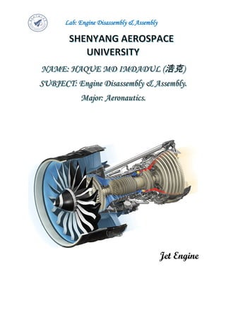
  • 1. Lab: Engine Disassembly & Assembly Jet Engine
  • 2. Lab: Engine Disassembly & Assembly Task1: The task is about the development of Aero Engines (Turbojet Engine; Turbofan Engine; Turboshaft Engine; Turboprop Engine). Answer: The development of Aero Engines Introduction An aero engine is a component of the propulsion system for an aircraft that generates mechanical power. Aero engines are almost always either lightweight piston engines or gas turbines, except for small multicopter UAVs which are almost always electric aircraft. There are many kinds of aero engines. Here, I have to discuss about develop of Aero Engines like Turbojet, Turbofan, Turboshaft and Turboprop Engine. The question asks about the development of Aero Engines that means all engines are Jet Engines which are also called Gas Turbine Engines. Jet engines move the airplane forward with a great force that is produced by a tremendous thrust and causes the plane to fly very fast. So, the main principal is Newton’s third law of motion. Sir Isaac Newton in the 18th century was the first to theorize that a rearward-channeled explosion could propel a machine forward at a great rate of speed. This theory was based on his third law of motion. As the hot air blasts backwards through the nozzle the plane moves forward. Frank Whittle, a British pilot, who designed and patented the first turbo jet engine in 1930. The Whittle engine first flew successfully in May, 1941. This engine featured a multistage compressor, and a combustion chamber, a single stage turbine and a nozzle. Jet Engine parts: Figure1 Jet Engine parts
  • 3. Lab: Engine Disassembly & Assembly All jet engines, which are also called gas turbines, work on the same principle. The engine sucks air in at the front with a fan. A compressor raises the pressure of the air. The compressor is made with many blades attached to a shaft. The blades spin at high speed and compress or squeeze the air. The compressed air is then sprayed with fuel and an electric spark lights the mixture. The burning gases expand and blast out through the nozzle, at the back of the engine. As the jets of gas shoot backward, the engine and the aircraft are thrust forward. As the hot air is going to the nozzle, it passes through another group of blades called the turbine. The turbine is attached to the same shaft as the compressor. Spinning the turbine causes the compressor to spin. While each of the engines are different, But, they share some parts in common. These are discussed below Fan: The fan is the first component in a turbofan. Figure1.1 Fan (red color) The large spinning fan sucks in large quantities of air. Most blades of the fan are made of titanium. It then speeds this air up and splits it into two parts. One part continues through the "core" or center of the engine, where it is acted upon by the other engine components. The second part "bypasses" the core of the engine. It goes through a duct that surrounds the core to the back of the engine where it produces much of the force that propels the airplane forward. This cooler air helps to quiet the engine as well as adding thrust to the engine.
  • 4. Lab: Engine Disassembly & Assembly Inlet: All turbine engines have an inlet to bring free stream air into the engine. The inlet sits upstream of the compressor and, while the inlet does no work on the flow, inlet performance has a strong influence on engine net thrust. As shown in the figures above, inlets come in a variety of shapes and sizes with the specifics usually dictated by the speed of the aircraft. Figure1.2 Inlet (Intake in British)  Subsonic inlets: For aircraft that cannot go faster than the speed of sound, like large airliners, a simple, straight, short inlet works quite well. On a typical subsonic inlet, the surface of the inlet from outside to inside is a continuous smooth curve with some thickness from inside to outside. The most upstream portion of the inlet is called the highlight, or the inlet lip. A subsonic aircraft has an inlet with a relatively thick lip.  Supersonic inlets: For a supersonic aircraft, the inlet must slow the flow down to subsonic speeds before the air reaches the compressor because of shock waves. Some supersonic inlets, like the one at the upper right, use a central cone to shock the flow down to subsonic speeds. Other inlets, like the one shown at the lower left, use flat hinged plates to generate the compression shocks, with the resulting inlet geometry having a rectangular cross section. This variable geometry inlet is used on the F-14 and F-15 fighter aircraft.  Hypersonic inlets: Inlets for hypersonic aircraft present the ultimate design challenge. For ramjet-powered aircraft, the inlet must bring the high speed external flow down to subsonic conditions in the burner. High stagnation temperatures are present in this speed regime and variable geometry may not be an option for the inlet designer because of possible flow leaks through the hinges. For scramjet-powered aircraft, the heat environment is even worse because the flight Mach number is higher than that for a ramjet-powered aircraft. Scramjet inlets are highly integrated with the fuselage of the aircraft. On the X-43A, the inlet includes the entire lower surface of the aircraft forward
  • 5. Lab: Engine Disassembly & Assembly of the cowl lip. Thick, hot boundary layers are usually present on the compression surfaces of hypersonic inlets. The flow exiting a scramjet inlet must remain supersonic.  Inlet efficiency: An inlet must operate efficiently over the entire flight envelope of the aircraft. At very low aircraft speeds, or when just sitting on the runway, free stream air is pulled into the engine by the compressor. At high speeds, a good inlet will allow the aircraft to maneuver to high angles of attack and sideslip without disrupting flow to the compressor. Because the inlet is so important to overall aircraft operation, it is usually designed and tested by the airframe company, not the engine manufacturer. But because inlet operation is so important to engine performance, all engine manufacturers also employ inlet aerodynamicists. Different airframers use different indices, but all of the indices are based on ratios of the local variation of pressure to the average pressure at the compressor face.  hypersonic inlets are normally characterized by their kinetic energy efficiency. If the airflow demanded by the engine is much less than the airflow that can be captured by the inlet, then the difference in airflow is spilled around the inlet. The airflow mis- match can produce spillage drag on the aircraft. Compressor: The compressor is the first component in the engine core. The compressor is made up of fans with many blades and attached to a shaft. The compressor squeezes the air that enters it into progressively smaller areas, resulting in an increase in the air pressure. This results in an increase in the energy potential of the air. The squashed air is forced into the combustion chamber. Figure1.3 Compressor
  • 6. Lab: Engine Disassembly & Assembly As shown in the above figure, there are two main types of compressors: axial and centrifugal.  In the picture, the compressor on the left is called an axial compressor because the flow through the compressor travels parallel to the axis of rotation. Modern large turbojet and turbofan engines usually use axial compressors.  The compressor on the right is called a centrifugal compressor because the flow through this compressor is turned perpendicular to the axis of rotation. Centrifugal compressors, which were used in the first jet engines, are still used on small turbojets and turboshaft engines and as pumps on rocket engines. Combustor: In the combustor the air is mixed with fuel and then ignited. There are as many as 20 nozzles to spray fuel into the airstream. The mixture of air and fuel catches fire. This provides a high temperature, high-energy airflow. The fuel burns with the oxygen in the compressed air, producing hot expanding gases. The inside of the combustor is often made of ceramic materials to provide a heat-resistant chamber. The heat can reach 2700. Figure1.4 Combustor-Burner There are three main types of combustors, and all three designs are found in modern gas turbines:  The burner at the left is an annular combustor with the liner sitting inside the outer casing which has been peeled open in the drawing. Many modern burners have an annular design.  The burner in the middle is an older can or tubular design. The photo at the top left shows some actual burner cans. Each can have both a liner and a casing, and the cans are arranged around the central shaft.
  • 7. Lab: Engine Disassembly & Assembly  A compromise design is shown at the right. This is a can-annular design, in which the casing is annular and the liner is can-shaped. The advantage to the can- annular design is that the individual cans are more easily designed, tested, and serviced. Turbine: The high-energy airflow coming out of the combustor goes into the turbine, causing the turbine blades to rotate. The turbines are linked by a shaft to turn the blades in the compressor and to spin the intake fan at the front. This rotation takes some energy from the high-energy flow that is used to drive the fan and the compressor. The gases produced in the combustion chamber move through the turbine and spin its blades. The turbines of the jet spin around thousands of times. They are fixed on shafts which have several sets of ball-bearing in between them. Figure1.5 Turbine Depending on the engine type, there may be multiple turbine stages present in the engine.  Turbofan and turboprop engines usually employ a separate turbine and shaft to power the fan and gear box respectively. Such an arrangement is termed a two spool engine. The power turbine shown on the upper left of the figure is for a two spool, turbofan engine.  For some high performance engines, an additional turbine and shaft is present to power separate parts of the compressor. This arrangement produces a three spool engine.
  • 8. Lab: Engine Disassembly & Assembly Nozzle: The nozzle is the exhaust duct of the engine. This is the engine part which actually produces the thrust for the plane. The energy depleted airflow that passed the turbine, in addition to the colder air that bypassed the engine core, produces a force when exiting the nozzle that acts to propel the engine, and therefore the airplane, forward. The combination of the hot air and cold air are expelled and produce an exhaust, which causes a forward thrust. The nozzle may be preceded by a mixer, which combines the high temperature air coming from the engine core with the lower temperature air that was bypassed in the fan. The mixer helps to make the engine quieter. Figure1.6 Nozzle As shown above, nozzles come in a variety of shapes and sizes depending on the mission of the aircraft.  Simple turbojets, and turboprops, often have a fixed geometry convergent nozzle as shown on the left of the figure.  Turbofan engines often employ a co-annular nozzle as shown at the top left. The core flow exits the center nozzle while the fan flow exits the annular nozzle. Mixing of the two flows provides some thrust enhancement and these nozzles also tend to be quieter than convergent nozzles.  Afterburning turbojets and turbofans require a variable geometry convergent-divergent - CD nozzle as shown on the left. In this nozzle, the flow first converges down to the minimum area or throat, then is expanded through the divergent section to the exit at the right. The flow is subsonic upstream of the throat, but supersonic downstream of the throat. All of the nozzles we have discussed thus far are round tubes. Recently, however, engineers have been experimenting with nozzles with rectangular exits. This allows the exhaust flow to
  • 9. Lab: Engine Disassembly & Assembly be easily deflected, or vectored, as shown in the middle of the figure. Changing the direction of the thrust with the nozzle makes the aircraft much more maneuverable. Turbojet Engine Figure2 Turbojet Engine The turbojet is an air breathing jet engine, typically used in aircraft. It consists of a gas turbine with a propelling nozzle. The gas turbine has an air inlet, a compressor, a combustion chamber, and a turbine (that drives the compressor). Two engineers, Frank Whittle in the United Kingdom and Hans von Ohain in Germany, developed the concept independently into practical engines during the late 1930s. A turbojet is a type of gas turbine engine that was originally developed for military fighters during World War II. When turbojets were introduced, the top speed of fighter aircraft equipped with them was at least 100 miles per hour faster than competing piston-driven aircraft. In the years after the war, the drawbacks of the turbojet gradually became apparent. Below about Mach 2, turbojets are very fuel inefficient and create tremendous amounts of noise. Early designs also respond very slowly to power changes, a fact that killed many experienced pilots when they attempted the transition to jets. These drawbacks eventually led to the downfall of the pure turbojet, and only a handful of types are still in production. The last airliner that used turbojets was the Concorde, whose Mach 2 airspeed permitted the engine to be highly efficient. Early Development and Designs: Early German turbojets had severe limitations on the amount of running they could do due to the lack of suitable high temperature materials for the turbines. British engines such as the Rolls-Royce Welland used better materials giving improved durability. The Welland was type-certified for 80 hours initially, later extended to 150 hours between overhauls, as a result of an extended 500-hour run being achieved in
  • 10. Lab: Engine Disassembly & Assembly tests. Despite their high maintenance, some of the early jet fighters are still operational with their original engines. General Electric in the United States was in a good position to enter the jet engine business due to its experience with the high-temperature materials used in their turbosuperchargers during World War II. Water injection was a common method used to increase thrust, usually during takeoff, in early turbojets that were thrust-limited by their allowable turbine entry temperature. The water increased thrust at the temperature limit, but prevented complete combustion, often leaving a very visible smoke trail. Allowable turbine entry temperatures have increased steadily over time both with the introduction of superior alloys and coatings, and with the introduction and progressive effectiveness of blade cooling designs. On early engines, the turbine temperature limit had to be monitored, and avoided, by the pilot, typically during starting and at maximum thrust settings. Automatic temperature limiting was introduced to reduce pilot workload and reduce the likelihood of turbine damage due to over-temperature. Design & Development: Air intake/ Inlet: An intake, or tube, is needed in front of the compressor to help direct the incoming air smoothly into the moving compressor blades. Older engines had stationary vanes in front of the moving blades. These vanes also helped to direct the air onto the blades. The air flowing into a turbojet engine is always subsonic, regardless of the speed of the aircraft itself. The intake has to supply air to the engine with an acceptably small variation in pressure (known as distortion) and having lost as little energy as possible on the way (known as pressure recovery). The ram pressure rise in the intake is the inlets contribution to the propulsion system overall pressure ratio and thermal efficiency. The intake gains prominence at high speeds when it transmits more thrust to the airframe than the engine does. Compressor: The compressor is driven by the turbine. It rotates at high speed, adding energy to the airflow and at the same time squeezing (compressing) it into a smaller space. Compressing the air increases its pressure and temperature. The smaller the compressor, the faster it turns. At the large end of the range, the GE-90-115 fan rotates at about 2,500 RPM, while a small helicopter engine compressor rotates around 50,000 RPM. Turbojets supply bleed air from the compressor to the aircraft for the environmental control system, anti-icing, and fuel tank pressurization, for example. The engine itself needs air at various pressures and flow rates to keep it running. This air comes from the compressor, and without it, the turbines would overheat, the lubricating oil would leak from the bearing cavities, the rotor thrust bearings would skid or be overloaded, and ice would form on the nose cone. The air from the compressor, called secondary air, is used for turbine cooling, bearing cavity
  • 11. Lab: Engine Disassembly & Assembly sealing, anti-icing, and ensuring that the rotor axial load on its thrust bearing will not wear it out prematurely. Supplying bleed air to the aircraft decreases the efficiency of the engine because it has been compressed, but then does not contribute to producing thrust. Bleed air for aircraft services is no longer needed on the turbofan-powered Boeing 787. Compressor types used in turbojets were typically axial or centrifugal. Early turbojet compressors had low pressure ratios up to about 5:1. Aerodynamic improvements including splitting the compressor into two separately rotating parts, incorporating variable blade angles for entry guide vanes and stators, and bleeding air from the compressor enabled later turbojets to have overall pressure ratios of 15:1 or more. For comparison, modern civil turbofan engines have overall pressure ratios of 44:1 or more. After leaving the compressor, the air enters the combustion chamber. Combustion chamber: The burning process in the combustor is significantly different from that in a piston engine. In a piston engine, the burning gases are confined to a small volume, and as the fuel burns, the pressure increases. In a turbojet, the air and fuel mixture burn in the combustor and pass through to the turbine in a continuous flowing process with no pressure build-up. Instead, a small pressure loss occurs in the combustor. The fuel-air mixture can only burn in slow-moving air, so an area of reverse flow is maintained by the fuel nozzles for the approximately stoichiometric burning in the primary zone. Further compressor air is introduced which completes the combustion process and reduces the temperature of the combustion products to a level which the turbine can accept. Less than 25% of the air is typically used for combustion, as an overall lean mixture is required to keep within the turbine temperature limits. Turbine: Hot gases leaving the combustor expand through the turbine. Typical materials for turbines include inconel and Nimonic. The hottest turbine vanes and blades in an engine have internal cooling passages. Air from the compressor is passed through these to keep the metal temperature within limits. The remaining stages do not need cooling. In the first stage, the turbine is largely an impulse turbine (similar to a pelton wheel) and rotates because of the impact of the hot gas stream. Later stages are convergent ducts that accelerate the gas. Energy is transferred into the shaft through momentum exchange in the opposite way to energy transfer in the compressor. The power developed by the turbine drives the compressor and accessories, like fuel, oil, and hydraulic pumps that are driven by the accessory gearbox. Nozzle: After the turbine, the gases expand through the exhaust nozzle producing a high velocity jet. In a convergent nozzle, the ducting narrows progressively to a throat. The nozzle pressure ratio on a turbojet is high enough at higher thrust settings to cause the nozzle to choke. If, however, a convergent-divergent de Laval nozzle is fitted, the divergent (increasing flow area) section allows the gases to reach supersonic velocity within the divergent section. Additional thrust is generated by the higher resulting exhaust velocity.
  • 12. Lab: Engine Disassembly & Assembly Thrust augmentation: Thrust was most commonly increased in turbojets injection or afterburning. Some engines used both at the same time. Afterburner: An afterburner or "reheat jetpipe" is a combustion chamber added to reheat the turbine exhaust gases. The fuel consumption is very high, typically four times that of the main engine. Afterburners are used almost exclusively on supersonic aircraft, most being military aircraft. Two supersonic airliners, Concorde and the Tu-144, also used afterburners as does Scaled Composites White Knight, a carrier aircraft for the experimental Space Ship One suborbital spacecraft. Net thrust: If the speed of the jet is equal to sonic velocity the nozzle is said to be choked. If the nozzle is choked the pressure at the nozzle exit plane is greater than atmospheric pressure, and extra terms must be added to the above equation to account for the pressure thrust. Figure2.1 Turbojet Thrust The rate of flow of fuel entering the engine is very small compared with the rate of flow of air. If the contribution of fuel to the nozzle gross thrust is ignored, the net thrust is: The speed of the jet Ve must exceed the true airspeed of the aircraft V0 if there is to be a net forward thrust on the airframe. The speed Ve can be calculated thermodynamically based on adiabatic expansion.
  • 13. Lab: Engine Disassembly & Assembly Cycle improvements: The operation of a turbojet is modelled approximately by the Brayton cycle. Figure2.2 The idealized Brayton cycle Where, P = pressure, V = volume, T = temperature, S = entropy, and Q = the heat added to or rejected by the system The efficiency of a gas turbine is increased by raising the overall pressure ratio, requiring higher-temperature compressor materials, and raising the turbine entry temperature, requiring better turbine materials and/or improved vane/blade cooling. It is also increased by reducing the losses as the flow progresses from the intake to the propelling nozzle. These losses are quantified by compressor and turbine efficiencies and ducting pressure losses. When used in a turbojet application, where the output from the gas turbine is used in a propelling nozzle, raising the turbine temperature increases the jet velocity. At normal subsonic speeds this reduces the propulsive efficiency, giving an overall loss, as reflected by the higher fuel consumption, or SFC. However, for supersonic aircraft this can be beneficial, and is part of the reason why the Concorde employed turbojets. Turbojet systems are complex systems therefore to secure optimal function of such system, there is a call for the newer models being developed to advance its control systems to implement the newest knowledge from the areas of automation.
  • 14. Lab: Engine Disassembly & Assembly Turbofan Engine Figure3 Schematic diagram of a high-bypass turbofan engine Principles: A turbofan engine has a large fan at the front, which sucks in air. Most of the air flows around the outside of the engine, making it quieter and giving more thrust at low speeds. Most of today's airliners are powered by turbofans. In a turbojet all the air entering the intake passes through the gas generator, which is composed of the compressor, combustion chamber, and turbine. In a turbofan engine only a portion of the incoming air goes into the combustion chamber. The remainder passes through a fan, or low-pressure compressor, and is ejected directly as a "cold" jet or mixed with the gas-generator exhaust to produce a "hot" jet. The objective of this sort of bypass system is to increase thrust without increasing fuel consumption. It achieves this by increasing the total air-mass flow and reducing the velocity within the same total energy supply. Bypass ratio: The bypass ratio (BPR) of a turbofan engine is the ratio between the mass flow rate of the bypass stream to the mass flow rate entering the core. A 10:1 bypass ratio, for example, means that 10 kg of air passes through the bypass duct for every 1 kg of air passing through the core. Efficiency: Since the efficiency of propulsion is a function of the relative airspeed of the exhaust to the surrounding air, propellers are most efficient for low speed, pure jets for high speeds, and ducted fans in the middle. Turbofans are thus the most efficient engines in the range of speeds from about 500 to 1,000 km/h (310 to 620 mph), the speed at which most commercial aircraft operate. Turbofans retain an efficiency edge over pure jets at low supersonic speeds up to roughly Mach 1.6 (1,960.1 km/h; 1,217.9 mph).
  • 15. Lab: Engine Disassembly & Assembly Thrust: The thrust (FN) generated by a turbofan depends on the effective exhaust velocity of the total exhaust, as with any jet engine, but because two exhaust jets are present the thrust equation can be expanded as: Figure3.1 Turbofan Thrust Nozzles: The cold duct and core duct's nozzle systems are relatively complex due to there being two exhaust flows. In high bypass engines the fan is generally situated in a short duct near the front of the engine and typically has a convergent cold nozzle, with the tail of the duct forming a low pressure ratio nozzle that under normal conditions will choke creating supersonic flow patterns around the core. The core nozzle is more conventional, but generates less of the thrust, and depending on design choices, such as noise considerations, may conceivably not choke. In low bypass engines the two flows may combine within the ducts, and share a common nozzle, which can be fitted with afterburner. Recent development: Aerodynamic modelling: Aerodynami is a mix of subsonic, transonic and supersonic airflow on a single fan/gas compressor blade in a modern turbofan. The airflow past the blades has to be maintained within close angular limits to keep the air flowing against an increasing pressure. Otherwise the air will come back out of the intake.
  • 16. Lab: Engine Disassembly & Assembly Blade technology: A 100 g turbine blade is subjected to 1,700 °C/3100 °F, at 17 bars/250 Psi and a centrifugal force of 40 kN/ 9,000 lbf, well above the point of plastic deformation and even above the melting point. Exotic alloys, sophisticated air cooling schemes and special mechanical design are needed to keep the physical stresses within the strength of the material. Rotating seals must withstand harsh conditions for 10 years, 20,000 missions and rotating at 10–20,000 rpm. Fan blades: Fan blades have been growing as jet engines have been getting bigger: each fan blade carries the equivalent of nine double-decker buses and swallows the volume of a squash court every second. Advances in computational fluid dynamics (CFD) modelling have permitted complex, 3D curved shapes with very wide chord, keeping the fan capabilities while minimizing the blade count to lower costs. Coincidentally, the bypass ratio grew to achieve higher propulsive efficiency and the fan diameter increased. Cycle improvements: According to simple theory, if the ratio of turbine rotor inlet temperature/(HP) compressor delivery temperature is maintained, the HP turbine throat area can be retained. However, this assumes that cycle improvements are obtained, while retaining the datum (HP) compressor exit flow function (non-dimensional flow). In practice, changes to the non-dimensional speed of the (HP) compressor and cooling bleed extraction would probably make this assumption invalid, making some adjustment to HP turbine throat area unavoidable. This means the HP turbine nozzle guide vanes would have to be different from the original. In all probability, the downstream LP turbine nozzle guide vanes would have to be changed anyway. Thrust growth: Thrust growth is obtained by increasing core power. There are two basic routes available:  hot route: increase HP turbine rotor inlet temperature  cold route: increase core mass flow Both routes require an increase in the combustor fuel flow and, therefore, the heat energy added to the core stream. The hot route may require changes in turbine blade/vane materials and/or better blade/vane cooling. The cold route can be obtained by one of the following:  adding T-stages to the LP/IP compression  adding a zero-stage to the HP compression  improving the compression process, without adding stages.  all of which increase both overall pressure ratio and core airflow. Future progress: Engine cores are shrinking as they are operating at higher pressure ratios and becoming more efficient, and become smaller compared to the fan as bypass ratios increase. Blade tip clearances are harder to maintain at the exit of the high-pressure compressor where blades are 0.5 in (13 mm) high or less, backbone bending further affects clearance control as the core is proportionately longer and thinner and the fan to low-pressure turbine driveshaft is in constrained space within the core.
  • 17. Lab: Engine Disassembly & Assembly Turboprop Engine Figure4 Schematic diagram showing the operation of a turboprop engine Principles: A turboprop engine is a jet engine attached to a propeller. The turbine at the back is turned by the hot gases, and this turns a shaft that drives the propeller. Some small airliners and transport aircraft are powered by turboprops. Like the turbojet, the turboprop engine consists of a compressor, combustion chamber, and turbine, the air and gas pressure is used to run the turbine, which then creates power to drive the compressor. Compared with a turbojet engine, the turboprop has better propulsion efficiency at flight speeds below about 500 miles per hour. Modern turboprop engines are equipped with propellers that have a smaller diameter but a larger number of blades for efficient operation at much higher flight speeds. To accommodate the higher flight speeds, the blades are scimitar-shaped with swept-back leading edges at the blade tips. Engines featuring such propellers are called propfans. Turboprop Thrust: Figure4.1 Turboprop Thrust
  • 18. Lab: Engine Disassembly & Assembly Technological aspects: Figure4.2 Propulsive efficiency comparison for various gas turbine engine configurations. Exhaust thrust in a turboprop is sacrificed in favour of shaft power, which is obtained by extracting additional power (up to that necessary to drive the compressor) from turbine expansion. Owing to the additional expansion in the turbine system, the residual energy in the exhaust jet is low. Consequently, the exhaust jet typically produces around or less than 10% of the total thrust. A higher proportion of the thrust comes from the propeller at low speeds and less at higher speeds. Propellers lose efficiency as aircraft speed increases, so turboprops are normally not used on high-speed aircraft above Mach 0.6-0.7. However, propfan engines, which are very similar to turboprop engines, can cruise at flight speeds approaching Mach 0.75. To increase propeller efficiency, a mechanism can be used to alter their pitch relative to the airspeed. A variable- pitch propeller, also called a controllable-pitch propeller, can also be used to generate negative thrust while decelerating on the runway. Additionally, in the event of an engine failure, the pitch can be adjusted to a vaning pitch (called feathering), thus minimizing the drag of the non- functioning propeller. Uses: Turboprop engines are generally used on small subsonic aircraft, but the Tupolev Tu- 114 can reach 470 kt (870 km/h, 541 mph). Large military and civil aircraft, such as the Lockheed L-188 Electra and the Tupolev Tu-95, have also used turboprop power. The Airbus A400M is powered by four Europrop TP400 engines, which are the third most powerful turboprop engines ever produced, after the eleven megawatt-output Kuznetsov NK- 12 and 10.4 MW-output Progress D-27 Reliability: Between 2012 and 2016, the ATSB observed 417 events with turboprop aircraft, 83 per year, over 1.4 million flight hours: 2.2 per 10,000 hours. Three were “high risk” involving engine malfunction and unplanned landing in single-engine Cessna 208 Caravans, four “medium risk” and 96% “low risk”. Two occurrences resulted in minor injuries due to engine malfunction and terrain collision in agricultural aircraft and five accidents involved aerial work: four in agriculture and one in an air ambulance.
  • 19. Lab: Engine Disassembly & Assembly Turboshaft Engine A turboshaft engine is a form of gas turbine that is optimized to produce shaft power rather than jet thrust. In concept, turboshaft engines are very similar to turbojets, with additional turbine expansion to extract heat energy from the exhaust and convert it into output shaft power. They are even more similar to turboprops, with only minor differences, and a single engine is often sold in both forms. Turboshaft engines are commonly used in applications that require a sustained high power output, high reliability, small size, and light weight. These include helicopters, auxiliary power units, boats and ships, tanks, hovercraft, and stationary equipment. Figure5 Schematic diagram showing the operation of a simplified turboshaft engine. The compressor spool is shown in green and the free / power spool is in purple. Overview: A turboshaft engine may be made up of two major parts assemblies: the 'gas generator' and the 'power section'. The gas generator consists of the compressor, combustion chambers with ignitors and fuel nozzles, and one or more stages of turbine. The power section consists of additional stages of turbines, a reduction system, and the shaft output. The gas generator creates the hot expanding gases to drive the power section. Depending on the design, the engine accessories may be driven either by the gas generator or by the power section.
  • 20. Lab: Engine Disassembly & Assembly In most designs, the gas generator and power section are mechanically separate so they can each rotate at different speeds appropriate for the conditions, referred to as a 'free power turbine'. A free power turbine can be an extremely useful design feature for vehicles, as it allows the design to forgo the weight and cost of complex multiple- ratio transmissions and clutches. The general layout of a turboshaft is similar to that of a turboprop. The main difference is a turboprop is structurally designed to support the loads created by a rotating propeller, as the propeller is not attached to anything but the engine itself. In contrast, turboshaft engines usually drive a transmission which is not structurally attached to the engine. The transmission is attached to the vehicle structure and supports the loads created instead of the engine. In practice, though, many of the same engines are built in both turboprop and turboshaft versions, with only minor differences. An unusual example of the turboshaft principle is the Pratt & Whitney F135-PW- 600 turbofan engine for the STOVL F-35B – in conventional mode it operates as a turbofan, but when powering the LiftFan, it switches partially to turboshaft mode to send 29,000 horsepower forward through a shaft and partially to turbofan mode to continue to send thrust to the main engine's fan and rear nozzle. Large helicopters use two or three turboshaft engines for redundancy. The Mil Mi-26 uses two Lotarev D-136 at 11,400 hp each, while the Sikorsky CH-53E Super Stallion uses three General Electric T64 at 4,380 hp each. Early turboshaft engines were adaptations of turboprop engines, delivering power through a shaft driven directly from the gas generator shafts, via a reduction gearbox. Examples of direct- drive turboshafts include marinised or industrial Rolls-Royce Dartengines. Principles: This is another form of gas-turbine engine that operates much like a turboprop system. It does not drive a propeller. Instead, it provides power for a helicopter rotor. The turboshaft engine is designed so that the speed of the helicopter rotor is independent of the rotating speed of the gas generator. This permits the rotor speed to be kept constant even when the speed of the generator is varied to modulate the amount of power produced. Turboshaft takeaway:  Pros:  Much higher power-to-weight ratio than piston engines  Typically, smaller than piston engines  Cons:  Loud  Gear systems connected to the shaft can be complex and break down
  • 21. Lab: Engine Disassembly & Assembly References [1] https://www.grc.nasa.gov/www/k-12/airplane/aturbj.html [2] https://www.grc.nasa.gov/www/k-12/airplane/aturbf.html [3] https://www.grc.nasa.gov/www/k-12/airplane/aturbp.html [4] https://www.grc.nasa.gov/www/k-12/UEET/StudentSite/engines.html [5] https://www.grc.nasa.gov/www/k-12/airplane/trbtyp.html [6] https://www.grc.nasa.gov/www/k-12/Missions/Jim/Project2_ans.htm **************END**************