IRJET- Design of Three Spindle Drilling, Spot facing Horizontal SPM for Cylinder head
•
0 likes•44 views

https://www.irjet.net/archives/V5/i3/IRJET-V5I3870.pdf

Recommended
Recommended
More Related Content
What's hot
What's hot (20)
Similar to IRJET- Design of Three Spindle Drilling, Spot facing Horizontal SPM for Cylinder head
Similar to IRJET- Design of Three Spindle Drilling, Spot facing Horizontal SPM for Cylinder head (20)
More from IRJET Journal
More from IRJET Journal (20)
Recently uploaded
Recently uploaded (20)
IRJET- Design of Three Spindle Drilling, Spot facing Horizontal SPM for Cylinder head
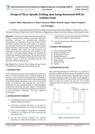
- 1. International Research Journal of Engineering and Technology (IRJET) e-ISSN: 2395-0056 Volume: 05 Issue: 03 | Mar-2018 www.irjet.net p-ISSN: 2395-0072 © 2018, IRJET | Impact Factor value: 6.171 | ISO 9001:2008 Certified Journal | Page 3712 Design of Three Spindle Drilling, Spot facing Horizontal SPM for Cylinder head Trupti P. Mali1, Dhanashree P. Mane2, Heena N. Mulla3, Neha M. Ingale4, Raja P. Poipkar5, A.A. Patwegar6 1,2,3,4,5 Student , Department of B.E. Mechanical Engineering, Shivaji University, Kolhapur, Maharashtra, India 6Assistant Professor, Department of B.E. Mechanical Engineering, Shivaji University, Kolhapur, Maharashtra, India ---------------------------------------------------------------------***--------------------------------------------------------------------- Abstract –Drilling and drilling-related operationslikespot facing or counter boring constitutes more than 60% of all machining processes in manufacturing industries. Consequently, it is important to know how to perform these operations properly. The aim of this paper is to design a special purpose machine which can perform drilling and spot facing operations simultaneously. The efforts are done to reduce operation time, reduce the cost of product and ultimately increase the productivity of the machine. In the same way it can reduce human fatigue and minimize the problem of availability of skilled labor. The concept is that the cutting tool is a combination of drill and spot facing tool. Hydraulic system is used for controlling the gear box movement and for holding the job. Key Words: Five spindles SPM, drilling and spot facing combination tools, Hydraulic system, Productivity. 1. INTRODUCTION In the conventional manner, only one job can be worked at a time for various operations such as drilling, tapping, spot facing, etc. but to increase the productivity, it demands a special purpose machine which will increase productivityby performing multiple operations in one cycle. Increasing the quality of production and reducing cost and time of production are very important factors in achieving higher productivity. Achieving this goal requires reconsidering current production methods that could lead to introduction of new production techniques and more advanced technologies. 2. DEFINATION OF PROBLEM 1) On drilling machine it is very difficult to spot face on intricate shapes and surfaces. 2) Performing required operations on all jobs on conventional machines is very time 33+consuming. 3) Parts or job holding or clamping on conventional machine is very difficult and time consuming for mass production. 4) To run the separate machines for separate operations, so many electrical parts or circuits are requiredwhich are consuminghigh electrical power, which is very costly for such operation. 5) Overall conventional method increases cost per unit production 3. PROJECT METHODOLOGY 1) Survey and study of SPMs 2) Study of cylinder head 3) Development of ideas 4) Design calculations 5) Drawing of parts and assembly 6) Ansys of parts 7) Manufacturing 8) Testing 4. DESCRIPTION OF SPM Fig.1. shows general layout of SPM. There is a rigid bed is provided on which all other systems are installed. Gear box provide a rotation motion of tools. Hydraulic system control the linear movement of gear box , hold the job. Jig plate is provided toholdthe job. Pin type locatorsare used.Drilltype fixture is used. Two motors are used one is to provide rotational motion to gear box and second is for hydraulic system. Fig -1: General Layout of SPM
- 2. International Research Journal of Engineering and Technology (IRJET) e-ISSN: 2395-0056 Volume: 05 Issue: 03 | Mar-2018 www.irjet.net p-ISSN: 2395-0072 © 2018, IRJET | Impact Factor value: 6.171 | ISO 9001:2008 Certified Journal | Page 3713 4. DESCRIPTION OF COMBINATION TOOL Fig -2: Tool design Fig.2. Shows schematic diagram of combinationdrilling-spot facing tool. Positive stop screw in the shank provides drill length adjustment. Dual set-screws in the cutter head provide secure support and driving force. Robust cutter heads can be sharpened repeatedly and are easily replaced. This tool is so designed that the operations of drilling and spot facing for cylinder head can be completed simultaneously. Spot facing provides a seat or flat surface at the entrance and surrounding area of a hole, it commonly done on casting where irregular surfaces are found. In spot facing, feed motion of the tool is parallel to axis of the work piece. It is followed by a mechanical drilling. After the initial hole is drilled, a larger well, or recess, is drilled into the material. This recess allowsto easy fittingsfortighteningthe stud nuts or fasteners. Highly recommended where spot facing must be perfectly aligned with drilled holes. 5. DESIGN CALCULATIONS 5.1 GEAR BOX DESIGN Fig -3: Gear box layout Here , 1,2,3 = drills as shown in 8,9 = spot face the figure 6 = main spindle 4,5,7 = idler shafts As per the customer requirement drilling size is 32.5mm. Accordingly further calculations are as follows: Diameter of drill = 32.5mm, From Centre Machine Tool data handbook, for drilling operation and for feed = 0.2mm, Cutting velocity = Cutting velocity = 70 m/min Now , V = ,Therefore by using formula, N = Table -1: Shaft and number of revolutions Part Pitch circle diameter No. of revolutions Drilling spindle 75 700 Idler shaft - I 72 730 Idler shaft - II 84 625 Main spindle 69 765 Idler shaft - III 84 630 Spot face spindle - I & II 75 705 5.2 HYDRAULIC SYSTEM DESIGN Figure shows working of hydraulic system Fig -4: Hydraulic system
- 3. International Research Journal of Engineering and Technology (IRJET) e-ISSN: 2395-0056 Volume: 05 Issue: 03 | Mar-2018 www.irjet.net p-ISSN: 2395-0072 © 2018, IRJET | Impact Factor value: 6.171 | ISO 9001:2008 Certified Journal | Page 3714 5.2.1 HYDRAULIC CYLINDE SELECTION Force required for moving gear box and holding the jobisup to 25 to 30 kg, for safety purpose 10kg of excess force is considered. Therefore, F = 30 + 10 = 40kg = 392.4N = 400N According to force requirement following dimensions for hydraulic cylinder are selected from catalogue, Bore diameter = 80mm Rod diameter = 45mm Stroke length = 325mm 5.2.2 HYDRAULIC OIL SELECTION Hydraulic Oil ISO Mineral based hydraulic oil Property Value in metric unit Value in US unit Density at 60°F (15.6°C 0.880*10³ kg/m³ 54.9 lb/ft³ Kinematic viscosity at 104°F (40°C) 68.0 cSt 68.0 cSt Kinematic viscosity at 212°F (100°C) 10.2 cSt 10.2 cSt Viscosity index 135 135 Flash point 204 ºC 400 ºF Pour Point -40 ºC -40 ºF Aniline Point 88 ºC 190 ºF Color Max.7.0 Max.7.0 5.3 JIG PLATE AND RENEWABLE BUSH DESIGN In plate type jig renewable bush is used. For this bush, liner is used on outside surface. Here liner is used because if the bush fails or breaks then the bush can be changed easily. Cutter diameter = 32mm, Cutter diameter = Inner diameter of bush, Therefore, Inner diameter of bush = 32mm, Outer diameter of bush = 38mm, Outer diameter of bush = Inner diameter of liner, Therefore, Inner diameter of liner = 38mm, From machine design data handbook, Outer diameter of liner = 50mm 3. CONCLUSIONS The cycle time is reduced by replacing separate machines for drilling and spot facing by a single special purpose machine to perform and simplify both the operations in cylinder head. The efforts are done to reduce operation time, reduce the cost of product and for increasing the productivity of the machine. REFERENCES [1] Anthony Esposito, “Fluid Power With Applications,” Sixth Edition, Pearson publication. [2] P. H. Joshi, “Machine Tool Handbook, Design and Operation” Tata McGraw-Hill Publishing Company Limited. [3] V. B. Bhandari, “Design of Machine Elements” Tata McGraw-Hill Publishing Company Limited. [4] S. K. Choudhury, A. K. Choudhury, Nirjhar Roy, “Elements of Workshop Technology”, Vol. II: Machine Tool, Twelfth edition.