IRJET- Pedal and Rope Operated Forklift

IRJET Journal
IRJET JournalFast Track Publications

https://www.irjet.net/archives/V6/i5/IRJET-V6I5310.pdf

International Research Journal of Engineering and Technology (IRJET) e-ISSN: 2395-0056
Volume: 06 Issue: 05 | May 2019 www.irjet.net p-ISSN: 2395-0072
© 2019, IRJET | Impact Factor value: 7.211 | ISO 9001:2008 Certified Journal | Page 1547
PEDAL AND ROPE OPERATED FORKLIFT
Adithya P1,Ajay Kumar M2, Narasimha Yadav GN3 , Shubham J Jadhav4, Ravi Babu D5, Dr Uday KumarPA6
1,2,3,4UG Students, department of Mechanical, SRSIT, Karnataka, INDIA
5Asst Professor, department of mechanical, SRSIT, Karnataka, INDIA
6HOD, department of mechanical, SRSIT, Karnataka, INDIA
---------------------------------------------------------------------***---------------------------------------------------------------------
Abstract - Many industries use forklifts for lifting heavy
goods, etc. these are applicable for large scale industries and
highly automated industries. Since the small industries
requires repeated movement of load from one station to
another station the use of these forklift will not be
economically. Hence, we decided to design a forklift for
transporting the load in easy and cost efficiency way for small
scale industries.
The idea is to lift the load and transport the material, heavy
load which cannot be lifted by humans
Key Words: Fork, Human Powered, Material Handling,
Small scale industry
1. INTRODUCTION
Forklift is a device which is used to transfer goods from one
place to other, there are fuel basedand batterybasedfork lift
These are short distance transport vehicle and pedal and
rope operated fork lift are used in small scale industries
Large forklift(fuel based or battery based) are used in
industries Running on fuel, they can generate torque but
this pedal and rope operated fork lift works Mechanically it
can lift minimum 50 KG
A population of india is large so that the main of industrial
company to fulfill customers requirement due to heavy
workload due to this the stress on theworkerisincreased by
this there is a effect on human health So, to minimise this
problem forklift are used in the industry.
2. OBJECTIVES
 Less energy consumption as it is operated by pedal
for the movement.
 As the overall cost is less it can be effectivelyusedin
small scale industries.
 The operation performed by using forkliftprovides
safety for an operator.
 Time consumption is less for performing loading
and unloading operations.
 Safety to workers at workplace.’
3. LITERATURE SURVEY
I. Design development and modellingforkliftbyUgale
Sachin, Salvi Tushar, Lanjekar Sachin, Kshirasagar
Prashanth: fabricated a forklift by using ratio
frequency technology. This makes it wireless and
increase visibility as well as safety.
II. Chunshan when forklift is loading and unloading it
is directlyunder allcargo weight and finished the
goods fork, handling, lifting. It is mainly compose of
door frame outrigger and cargo, guide wheel chain
and lifting oil cylinder.
III. Aashish Kumar L Sharnagati, M.S.Tufail developed
of robotic forklift to handlepallrtizedmaterial using
local sensing so that it needs electricity.
4. CONSTRUCTION AND WORKING MECHANISM
FIG-1. Design of Forklift
Pedal and rope operated fork lift consists of frame made up
of steel bars which are welded together to form a structure.
The wheels are provided at the front and back for the
movement of fork lift wheels are connected to front axle.
Chain and sprocket mechanism are providedfortheforward
and backward movement of forklift which is placed at back
side.
International Research Journal of Engineering and Technology (IRJET) e-ISSN: 2395-0056
Volume: 06 Issue: 05 | May 2019 www.irjet.net p-ISSN: 2395-0072
© 2019, IRJET | Impact Factor value: 7.211 | ISO 9001:2008 Certified Journal | Page 1548
The forklift consists of three mechanism:
 Lifting mechanism
 Steering mechanism
 Pedaling mechanism
4.1 LIFTING MECHANISM:
Lifting below is a chain block diagram of mechanism gear
assembly chain block system liftsthedesiredload.Itconsists
of gear, chain and a pulley. The worm starts rotating by the
rotation of pulley which in turn rotates the wormwheel.The
chain which is fixed to the output of gear helps in lifting the
load placed in the fork of the forklift. The belowfigureshows
lifting mechanism.
FIG-2 Block diagram of lifting mechanism
4.2 STEERING MECHANISM:
Steering is controlling the movement of forklift which is
used to control the movements It consists of bell crank
lever, tie rods, steering rod with pivot pin. tie rods one end
are connected to the pivot pin and the other end of the tie
rod is connected to the longer arm of the bell crank lever on
each side. The front wheels are held by short arm. The pivot
pin are connected to the steering rod. The wheels are
steered by rotating steer wheel.
4.3 PEDALLING MECHANISM:
This consists of gear box. The gear box has two shafts. Input
shafts rotate due to the pedalling, hence gear fixed to the
shaft rotates which mates with the gear on output shaft. An
idler gear is placed to move the vehicle in forward direction.
The gear assembly is disengaged when the lever direction is
changed and the other two gears are engaged which enables
the vehicle to move in reverse direction.
FIG-3 Block diagram of Pedalling Mechanism
5. COMPONENTS DESCRIPTION:
Different components used in this project are as given
below:-
5.1 BASE(CHASSIS):-
 The chassis is fabricated from mild steel.
 This is done for ease of fabrication, and to reduce
the overall weight.
 The chassis was designed to take a static load of
3kg.
 The flange which holds the motor was designed
using Aluminium and is bolted to the chassis.
 So that the driving motors can easily accommodate
below the chassis.
5.2 SLIDER:-
It is a rectangular shaped which is in between two
channels of Aluminium which slides up and down easily to
lift and it lowers the load up to a desired limit by using rope
which is connected to the DC Motor.
5.3 SHAFT:-
 A shaft is an element which transmits
power.
 The power is obtained to the shaft by tangential
force and various machines are linked to the shaft
due to this resultant force is setup.
 Pulleys, gears, etc., are mounted on shaft, so that
power is transferred from one place to other
 Bending of shaft occurs due to the forceexertedand
other member present on it.
5.4 NYLON ROPE:-
A nylon rope is used because it withstands certain load
The rope transmits power by means of pulleys which rotate
at a speed. The power transmitted depends upon the
following factors:
 The velocity of rope.
 The tension under which the rope is placed on the
pulleys.
 The condition under which the rope is used.
5.5 PULLEYS:-
 Transmission of power takes place from one point
to other by means of pulley with belt or rope.
 The velocity ratio is the inverse ratio of the
diameter of the driving and driven pulleys .so ,
selection of pulley diameter is done precisely to
have a desired velocity.
 To allow the belt or rope to travel in a normal to
pulley then the pulley must be in perfect alignment.
International Research Journal of Engineering and Technology (IRJET) e-ISSN: 2395-0056
Volume: 06 Issue: 05 | May 2019 www.irjet.net p-ISSN: 2395-0072
© 2019, IRJET | Impact Factor value: 7.211 | ISO 9001:2008 Certified Journal | Page 1549
5.6 DC MOTOR:-
 Electric energy is converted into mechanical energy
by an motor.
 It works on the principle of fleming’s left hand rule
that mechanical forceisexperienced whena current
carrying conductor is placed in a magnetic field.
5.7 PEDAL:-
Pedal is used for the movement of the forklift, when the
operator pedals, the pedal connected to the chain and gear
box starts rotating due to which interconnected flywheel in
the wheel starts to rotate by this forklift moves forward or
backward.
5.8 WORM WHEEL:-
This material is made up of cast steel, crank pulley
rotates the worm. Gear with chain is connected to the fork
frame to lift the load. It is also called as worm gear.
6. FUTURE SCOPE
As this is used for small scale industries it is just a basic, for
the future an advancement can be done by
 Lifting can be done by hydraulics using pascal’s law
 Engines can be replaced instead of pedalling
mechanism.
 Increase of worm dimensions can increase the
mechanism.
 Steering also can be replaced by rack and pinion.
7. CONCLUSION
This machine will be useful for small scale industries, it is
easy to operate and labour cost is also less. it can lift limited
load if some modification will be done then the limit can be
raised. It can also deal in a field of unused metals.
REFERENCES
1. Dr.R.N. Mall (2013), Automated Guided Vehicle,
ISBN 2091 Journal, MMMEC, Gorakhpur.
2. Kenneth B. Ackerman (1990), Forklifts and Other
Mobile Equipment, Practical Handbook of
Warehousing
3. R S Khurmi, J.K Gupta (2005), A text book of
Machine Design.
4. S S Rattan (2009), Theory Of Machines,ProfessorOf
Mechanical Engineering, National Institute Of
Technology, Kurukshetra.
5. V B Bhandari (2010), Design Of Machine Elements,
Retired Professor And Head Department Of
Mechanical Engineering, Vishwakarma Institute Of
Technology, Pune.
6. [6] J B Gupta (2011), Basic Electrical & Electronics
Engineering.
7. B L Thareja, A K Thareja Revised By S G Tarnekar
(2005), Electrical Technology, Former Professor &
Head, Electrical Engineering Department,
Visvesaraya National Institute Of Technology,
Nagpur.
8. From Vol. IV Number 1 of Warehousing Forum
©1988, The Ackerman Co.
9. Significant contributions to theAGVSmaterial came
from Tom Ewers of Kalmar AC Handling Systems,
Bob MacEwan of Clark Lift of Columbus, and Russ
Gilmore of Autocon in Dayton, Ohio. Portions
appeared in Vol. 20, No. 6, Warehousing and
Distribution Productivity Report, Marketing
Publications, Inc., Silver Spring, MD.
10. Conte M, Pasquali M (2009) Impact of innovative
ILHYPOS super capacitors on a fuel cell vehicle,
international electric vehicle symposium EVS-24.
Stavanger, Norway [11] Conte M (2010) Super
capacitors technical requirements for new
applications. Fuel Cells

Recommandé

PEDAL OPERATED FORK LIFTPEDAL OPERATED FORK LIFT
PEDAL OPERATED FORK LIFTKunal Kotian
5.2K vues56 diapositives
REMOTE OPERATED FORK LIFTREMOTE OPERATED FORK LIFT
REMOTE OPERATED FORK LIFTSuchit Moon
5.1K vues44 diapositives
Mobile wheel lathe 1AK200 manualMobile wheel lathe 1AK200 manual
Mobile wheel lathe 1AK200 manualKnit
74 vues5 diapositives
Northern railwayNorthern railway
Northern railwaymanish tiwari
382 vues45 diapositives

Contenu connexe

Tendances(19)

IET EMUIET EMU
IET EMU
Mohamed Awadalla1.5K vues
Automobile unit 1   vehicle structure and engines.Automobile unit 1   vehicle structure and engines.
Automobile unit 1 vehicle structure and engines.
RMK College of Engineering and Technology181 vues
Training reportTraining report
Training report
Sumit Kumar6K vues
Four wheel steering system for Automobile Four wheel steering system for Automobile
Four wheel steering system for Automobile
ijiert bestjournal119 vues
Steering system automobile Steering system automobile
Steering system automobile
PEC University Chandigarh2.7K vues
Emu car shed ghaziabadEmu car shed ghaziabad
Emu car shed ghaziabad
Abhishek Singh6.1K vues
PROJECT REPORTPROJECT REPORT
PROJECT REPORT
shyam veer rajawat2.8K vues
Ijmet 10 01_172Ijmet 10 01_172
Ijmet 10 01_172
IAEME Publication110 vues
 Zero Turn Vehicle  Zero Turn Vehicle
Zero Turn Vehicle
IRJET Journal214 vues
Mech.pdfMech.pdf
Mech.pdf
Romio Rk458 vues
Maintenace manual for wagonsMaintenace manual for wagons
Maintenace manual for wagons
SrinivasaRao Guduru46.6K vues
Introduction to automobileIntroduction to automobile
Introduction to automobile
Ratnadeepsinh Jadeja1.1K vues

Similaire à IRJET- Pedal and Rope Operated Forklift(20)

A0470101011A0470101011
A0470101011
ijceronline297 vues
IRJET-  	  Footstep Power GenerationIRJET-  	  Footstep Power Generation
IRJET- Footstep Power Generation
IRJET Journal54 vues
IRJET- Smart Shock AbsorberIRJET- Smart Shock Absorber
IRJET- Smart Shock Absorber
IRJET Journal99 vues

Plus de IRJET Journal(20)

Dernier(20)

performance uploading.pptxperformance uploading.pptx
performance uploading.pptx
SanthiS107 vues
Wire RopeWire Rope
Wire Rope
Iwiss Tools Co.,Ltd8 vues
SICTECH CORPORATE PRESENTATIONSICTECH CORPORATE PRESENTATION
SICTECH CORPORATE PRESENTATION
SiCtechInduction15 vues
Paper 3.pdfPaper 3.pdf
Paper 3.pdf
Javad Kadkhodapour6 vues
IWISS Catalog 2022IWISS Catalog 2022
IWISS Catalog 2022
Iwiss Tools Co.,Ltd22 vues
Deutsch CrimpingDeutsch Crimping
Deutsch Crimping
Iwiss Tools Co.,Ltd13 vues
Object Oriented Programming with JAVAObject Oriented Programming with JAVA
Object Oriented Programming with JAVA
Demian Antony D'Mello49 vues
Investor PresentationInvestor Presentation
Investor Presentation
eser sevinç10 vues
Saikat Chakraborty Java Oracle Certificate.pdfSaikat Chakraborty Java Oracle Certificate.pdf
Saikat Chakraborty Java Oracle Certificate.pdf
SaikatChakraborty7871489 vues
Sanitary Landfill- SWM.pptxSanitary Landfill- SWM.pptx
Sanitary Landfill- SWM.pptx
Vinod Nejkar5 vues
PlumbingPlumbing
Plumbing
Iwiss Tools Co.,Ltd9 vues
SEMI CONDUCTORSSEMI CONDUCTORS
SEMI CONDUCTORS
pavaniaalla200515 vues
LFA-NPG-Paper.pdfLFA-NPG-Paper.pdf
LFA-NPG-Paper.pdf
harinsrikanth40 vues
Codes and Conventions.pptxCodes and Conventions.pptx
Codes and Conventions.pptx
IsabellaGraceAnkers5 vues

IRJET- Pedal and Rope Operated Forklift

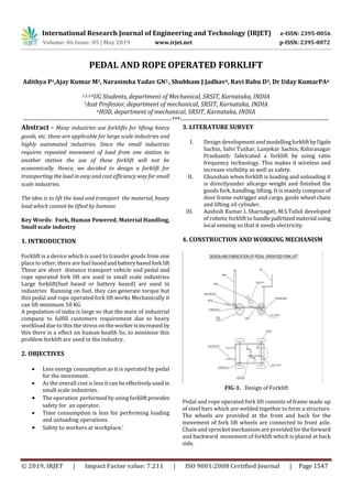
  • 1. International Research Journal of Engineering and Technology (IRJET) e-ISSN: 2395-0056 Volume: 06 Issue: 05 | May 2019 www.irjet.net p-ISSN: 2395-0072 © 2019, IRJET | Impact Factor value: 7.211 | ISO 9001:2008 Certified Journal | Page 1547 PEDAL AND ROPE OPERATED FORKLIFT Adithya P1,Ajay Kumar M2, Narasimha Yadav GN3 , Shubham J Jadhav4, Ravi Babu D5, Dr Uday KumarPA6 1,2,3,4UG Students, department of Mechanical, SRSIT, Karnataka, INDIA 5Asst Professor, department of mechanical, SRSIT, Karnataka, INDIA 6HOD, department of mechanical, SRSIT, Karnataka, INDIA ---------------------------------------------------------------------***--------------------------------------------------------------------- Abstract - Many industries use forklifts for lifting heavy goods, etc. these are applicable for large scale industries and highly automated industries. Since the small industries requires repeated movement of load from one station to another station the use of these forklift will not be economically. Hence, we decided to design a forklift for transporting the load in easy and cost efficiency way for small scale industries. The idea is to lift the load and transport the material, heavy load which cannot be lifted by humans Key Words: Fork, Human Powered, Material Handling, Small scale industry 1. INTRODUCTION Forklift is a device which is used to transfer goods from one place to other, there are fuel basedand batterybasedfork lift These are short distance transport vehicle and pedal and rope operated fork lift are used in small scale industries Large forklift(fuel based or battery based) are used in industries Running on fuel, they can generate torque but this pedal and rope operated fork lift works Mechanically it can lift minimum 50 KG A population of india is large so that the main of industrial company to fulfill customers requirement due to heavy workload due to this the stress on theworkerisincreased by this there is a effect on human health So, to minimise this problem forklift are used in the industry. 2. OBJECTIVES  Less energy consumption as it is operated by pedal for the movement.  As the overall cost is less it can be effectivelyusedin small scale industries.  The operation performed by using forkliftprovides safety for an operator.  Time consumption is less for performing loading and unloading operations.  Safety to workers at workplace.’ 3. LITERATURE SURVEY I. Design development and modellingforkliftbyUgale Sachin, Salvi Tushar, Lanjekar Sachin, Kshirasagar Prashanth: fabricated a forklift by using ratio frequency technology. This makes it wireless and increase visibility as well as safety. II. Chunshan when forklift is loading and unloading it is directlyunder allcargo weight and finished the goods fork, handling, lifting. It is mainly compose of door frame outrigger and cargo, guide wheel chain and lifting oil cylinder. III. Aashish Kumar L Sharnagati, M.S.Tufail developed of robotic forklift to handlepallrtizedmaterial using local sensing so that it needs electricity. 4. CONSTRUCTION AND WORKING MECHANISM FIG-1. Design of Forklift Pedal and rope operated fork lift consists of frame made up of steel bars which are welded together to form a structure. The wheels are provided at the front and back for the movement of fork lift wheels are connected to front axle. Chain and sprocket mechanism are providedfortheforward and backward movement of forklift which is placed at back side.
  • 2. International Research Journal of Engineering and Technology (IRJET) e-ISSN: 2395-0056 Volume: 06 Issue: 05 | May 2019 www.irjet.net p-ISSN: 2395-0072 © 2019, IRJET | Impact Factor value: 7.211 | ISO 9001:2008 Certified Journal | Page 1548 The forklift consists of three mechanism:  Lifting mechanism  Steering mechanism  Pedaling mechanism 4.1 LIFTING MECHANISM: Lifting below is a chain block diagram of mechanism gear assembly chain block system liftsthedesiredload.Itconsists of gear, chain and a pulley. The worm starts rotating by the rotation of pulley which in turn rotates the wormwheel.The chain which is fixed to the output of gear helps in lifting the load placed in the fork of the forklift. The belowfigureshows lifting mechanism. FIG-2 Block diagram of lifting mechanism 4.2 STEERING MECHANISM: Steering is controlling the movement of forklift which is used to control the movements It consists of bell crank lever, tie rods, steering rod with pivot pin. tie rods one end are connected to the pivot pin and the other end of the tie rod is connected to the longer arm of the bell crank lever on each side. The front wheels are held by short arm. The pivot pin are connected to the steering rod. The wheels are steered by rotating steer wheel. 4.3 PEDALLING MECHANISM: This consists of gear box. The gear box has two shafts. Input shafts rotate due to the pedalling, hence gear fixed to the shaft rotates which mates with the gear on output shaft. An idler gear is placed to move the vehicle in forward direction. The gear assembly is disengaged when the lever direction is changed and the other two gears are engaged which enables the vehicle to move in reverse direction. FIG-3 Block diagram of Pedalling Mechanism 5. COMPONENTS DESCRIPTION: Different components used in this project are as given below:- 5.1 BASE(CHASSIS):-  The chassis is fabricated from mild steel.  This is done for ease of fabrication, and to reduce the overall weight.  The chassis was designed to take a static load of 3kg.  The flange which holds the motor was designed using Aluminium and is bolted to the chassis.  So that the driving motors can easily accommodate below the chassis. 5.2 SLIDER:- It is a rectangular shaped which is in between two channels of Aluminium which slides up and down easily to lift and it lowers the load up to a desired limit by using rope which is connected to the DC Motor. 5.3 SHAFT:-  A shaft is an element which transmits power.  The power is obtained to the shaft by tangential force and various machines are linked to the shaft due to this resultant force is setup.  Pulleys, gears, etc., are mounted on shaft, so that power is transferred from one place to other  Bending of shaft occurs due to the forceexertedand other member present on it. 5.4 NYLON ROPE:- A nylon rope is used because it withstands certain load The rope transmits power by means of pulleys which rotate at a speed. The power transmitted depends upon the following factors:  The velocity of rope.  The tension under which the rope is placed on the pulleys.  The condition under which the rope is used. 5.5 PULLEYS:-  Transmission of power takes place from one point to other by means of pulley with belt or rope.  The velocity ratio is the inverse ratio of the diameter of the driving and driven pulleys .so , selection of pulley diameter is done precisely to have a desired velocity.  To allow the belt or rope to travel in a normal to pulley then the pulley must be in perfect alignment.
  • 3. International Research Journal of Engineering and Technology (IRJET) e-ISSN: 2395-0056 Volume: 06 Issue: 05 | May 2019 www.irjet.net p-ISSN: 2395-0072 © 2019, IRJET | Impact Factor value: 7.211 | ISO 9001:2008 Certified Journal | Page 1549 5.6 DC MOTOR:-  Electric energy is converted into mechanical energy by an motor.  It works on the principle of fleming’s left hand rule that mechanical forceisexperienced whena current carrying conductor is placed in a magnetic field. 5.7 PEDAL:- Pedal is used for the movement of the forklift, when the operator pedals, the pedal connected to the chain and gear box starts rotating due to which interconnected flywheel in the wheel starts to rotate by this forklift moves forward or backward. 5.8 WORM WHEEL:- This material is made up of cast steel, crank pulley rotates the worm. Gear with chain is connected to the fork frame to lift the load. It is also called as worm gear. 6. FUTURE SCOPE As this is used for small scale industries it is just a basic, for the future an advancement can be done by  Lifting can be done by hydraulics using pascal’s law  Engines can be replaced instead of pedalling mechanism.  Increase of worm dimensions can increase the mechanism.  Steering also can be replaced by rack and pinion. 7. CONCLUSION This machine will be useful for small scale industries, it is easy to operate and labour cost is also less. it can lift limited load if some modification will be done then the limit can be raised. It can also deal in a field of unused metals. REFERENCES 1. Dr.R.N. Mall (2013), Automated Guided Vehicle, ISBN 2091 Journal, MMMEC, Gorakhpur. 2. Kenneth B. Ackerman (1990), Forklifts and Other Mobile Equipment, Practical Handbook of Warehousing 3. R S Khurmi, J.K Gupta (2005), A text book of Machine Design. 4. S S Rattan (2009), Theory Of Machines,ProfessorOf Mechanical Engineering, National Institute Of Technology, Kurukshetra. 5. V B Bhandari (2010), Design Of Machine Elements, Retired Professor And Head Department Of Mechanical Engineering, Vishwakarma Institute Of Technology, Pune. 6. [6] J B Gupta (2011), Basic Electrical & Electronics Engineering. 7. B L Thareja, A K Thareja Revised By S G Tarnekar (2005), Electrical Technology, Former Professor & Head, Electrical Engineering Department, Visvesaraya National Institute Of Technology, Nagpur. 8. From Vol. IV Number 1 of Warehousing Forum ©1988, The Ackerman Co. 9. Significant contributions to theAGVSmaterial came from Tom Ewers of Kalmar AC Handling Systems, Bob MacEwan of Clark Lift of Columbus, and Russ Gilmore of Autocon in Dayton, Ohio. Portions appeared in Vol. 20, No. 6, Warehousing and Distribution Productivity Report, Marketing Publications, Inc., Silver Spring, MD. 10. Conte M, Pasquali M (2009) Impact of innovative ILHYPOS super capacitors on a fuel cell vehicle, international electric vehicle symposium EVS-24. Stavanger, Norway [11] Conte M (2010) Super capacitors technical requirements for new applications. Fuel Cells