very simple VLF Pocket receiver.pdf

ivan ion
ivan ionvideo editor, electronist, drone pilot, it repair, it mentenance à RFF

electronica aplicata antene radioamatori

A very simple VLF Pocket receiver
By Wilfried Fritz, DJ1WF
Detecting and listening to VLF Signals became so easy since most people own a notebook. A simple
peace of software combined with a wire antenna connected to the soundcard's input is enough to
pick up VLF signals. Another method listening to VLF signals is to convert them up into a frequency
range an amateur radio transceiver or -receiver covers. All these methods require long wire antennas
and filters for AM broadcast stations and sometimes extensive additional equipment.
But what should you do if you do not want to carry a notebook or other extensive RX components
with long wires and so on every time? Wouldn't it be nice to have a small receiver which can be
carried in the pocket to listen to VLF signals spontaneously? The following receiver concept may give
an idea how to build a tiny and sufficiently performant RX without using expensive filters.
Preliminary considerations
A VLF receiver needs a good selectivity. And the receiver must be able to detect CW signals like RSDN-20 and SAQ. Based on
these requirements a superheterodyne RX with BFO can be a good choice. The first idea to get a good selectivity is using a very
narrow IF filter. But these filters are very expensive and sometimes hard to get. The bandwidth of cheap ceramic IF filters is
normally greater than 6 kHz, too much to separate the different signals sufficiently. An additional problem is the presence of very
strong military data transmitters above 18kHz and the enormous RF level difference to the relatively weak RSDN-20 signals and,
of course SAQ. One way to solve the problem may be to combine a cheap 6 kHz IF filter like CFU455HT or similar in the IF stage
and a narrow audio filter after demodulation. While thinking about this idea more detailed, the next problem will occur. When you
adjust the RX to the upper RSDN-20 transmitter at 14,88 kHz, the high power military data transmitters will pass the IF filter, too
and will block the following IF amplifier. But even if this fact seems to be a knockout for the use of a cheap IF filter there is a way
to solve the problem while using a trick. Nobody tells you to adjust the VFO so that the desired signal passes the IF filter exactly
at it's center frequency. It is only necessary this signal will pass the filter somewhere. So you can adjust the RX VFO in a way the
desired signal passes the filter on it's upper edge. The effect is the strong data transmitter signals above will be cut off because it
is out of the passthrogh range, only signal rests will pass the filter. When the BFO frequency is adjusted to the lower edge of the
filter transmission range, a major difference between the RSDN-20 audio signal for example and the unwanted signals above
allows to extract the RSDN-20 with a narrow audio filter. The following picture shows the mixer output spectrum when the VFO is
adjusted as described before.
Building the receiver and functional description
A good way finding out which parts can be used is to have a look into the component box. While lookin into my box I found an
old TDA4100 and a CFU455HT IF filter which I had extracted from an old radio several years before. The TDA4100 is not
EVO PDF Tools Demo
produced any more, but still available at different suppliers. If you cannot get a TDA4100, an equivalent type A4100D is
available. So the construction of the "receiver's heart" and some additional ones to test if the result can be reproduced was no
severe problem. The rest of the receiver could be built with common components. The following schematic shows how the
receiver works.
Click here for full resolution scheme
For avoiding the use of a long wire antenna, the first stage is a high impedance preamplifier. With this stage a 30cm telescopic
rod antenna is enough to pick up the VLF signals. A longer antenna will improve the signal/noise ratio, but also may cause
additional problems. The reason is the increasing RF level which can overdrive the mixer stage when using longer antennas
without level compensation. The preamp's output is connected to the TDA4100 mixer input via a potentiometer. This allows to
adjust the mixer input level in an optimal way.
The advantage in using an AM RX circuit like the TDA 4100 is the presence of a mixer, VFO, IF amplifier and demodulator unit in
one integrated circuit. Only a BFO has to be added to hear the CW signals. For keeping it simple, the BFO circuit is built around a
455 kHz ceramic resonator. The frequency tolerance is quite bigger than circuits using a crystal, so the BFO frequency can be
changed to several kHz away from the center. In this special case, the BFO oscillates at 452kHz. The complete IF spectrum, BFO
signal included, passes the internal IF amplifier. The VFO is included in the TDA 4100. It can be adjusted with a variable capacitor
extracted from an old radio or, like in this example, with a varicap diode. The shown dimensions allow to cover a frequency range
from 0 to 150kHz, so that higher frequent signals than VLF like time signal and LF-remote control transmitters, LORAN, and DWD
Weather fax signals can be picked up with this receiver, too. The demodulated audio signal is available at Pin 19 where an audio
low pass filter is connected. Following the audio lowpass, there is an additional audio bandpass filter. The combination of the low-
and bandpass-filter supresses the unwanted military data signal rests passing the IF filter in a sufficient way. The last stage is
made with a LM 386-1, a very cheap audio amplifier circuit, to drive a small loudspeaker. The circuit can be built in metal or even
plastic enclosures. The following picture shows some suggestions.
EVO PDF Tools Demo
The left receiver was installed into a common Hammond die cast enclosure. The receiver in the middle was built in an old PC
loudspeaker housing and the right one was made using a cheap ABS enclosure.
It is not necessary to create a PCB, a hole grid board like shown below or even an ugly bug is ok. The only important thing is to
take care about proper grounding all over the circuit to avoid oscillaton. An aluminium foil below will reduce the capacitive effects
caused by the human hand while holding the receiver.
Reception results
Even if the circuit is very simple and using cheap filters, the weak RSDN-20 signals can be heard clearly when adjusting the
receiver properly. It is necessary to listen in a clean VLF environment. Human made signals coming from switching power
supplies and so on may cover the weak signals. Before writing the article, I could not test SAQ reception on 17,2kHz because the
signal is very rare. It is only present for some minutes during 2-3 events in the year. But now, I could pick up the SAQ signal
during transmissions in summer and winter time with good results. There were some weak interferences from the exorbitant
strong data signals beside, but they were much weaker than the desired signals and no problem during listening.
EVO PDF Tools Demo
For getting an impression how such a receiver can work, I have a uploaded some video clips. Please enter the keywords vlf
pocket receiver, maybe with the extension dj1wf into a search engine, and you will get a link to some youtube videos.
Thinking about improvements and schematic variations
The described receiver is a very simple one, made of cheap parts. It cannot give a performance even God cannot improve. The
concept shall give an idea how to build a tiny VLF receiver which can be carried in the pocket for spontaneous VLF listening on
several locations. There is much space for own ideas to make the receiver perfect. The described concept is no law how to build a
tiny VLF receiver and what parts have to be used. Using AM receiver circuits will simplify the construction, but it is also possible
to build a RX even using discrete components. On the other hand, the audio filters also can be built using integrated circuits and
so on. As I said, there is a lot of space for own ideas. This circuit works well, but it is not the last spoken word.
Following there are some possible ideas how to make the receiver better:
1. The 6 kHz IF filter bandwidth should not be increased, but there may be a way to narrow it. I found out there are 455kHz and
450 kHz IF filters with 6 kHz bandwidth available and still manufactured. If you combine these filters, the overlapping
transmission ranges will result in a lower combined bandwidth. When doing this, you will have to pay attention to the resulting
transmission attenuation in the passthrough range which may decrease the effect of narrowing the bandwidth a little bit. So an
additional IF amplifier stage between the filters may become necessary.
2. The selectivity can be improved by adding a second audio bandpass stage.
3. Maybe it can be a good idea to play with the audio bandpass center frequency. You have to look at the whole system,
beginning with the IF filter bandwidth and ending with the loudspeaker's frequency response.
4. A major problem is the audio feedback when adjusting the RX below 5 kHz at high audio levels. This cannot be avoided when
concentrating all the parts in a small enclosure combined with high amplification values. So if you need high audio levels without
the risk of audio feedback, it may be a way to separate the RX unit and the audio amplifier unit.
5. There is only one additional simple input filter to block strong broadcast stations in the MW range. It consists of a 1mH coil
and a 100n capacitor. Combined with the lowpass consisting of the 680k resistors and the FETs internal capacity, that's enough to
use the RX in a distance of 10km to a 20kW AM broadcast transmitter on 828kHz without interferences. But in some locations it
may become necessary to use additional filters, like choking circuits or similar for suppressing image frequencies from strong AM
radio stations in the MW range.
6. When using a varicap VFO adjustment, the tuning voltage has to be stabilized. This is a problem when using small 9V
batteries. If you want to cover a frequency range up to 150kHz, a maximum tuning voltage around 6V is necessary. High audio
levels will cause a battery voltage breakdown, so that the tuning voltage may breakdown, too. This will cause an unwanted
frequency deviation. This can be avoided by using a separate small 12V battery with following voltage stabilisation to 6V.
7. An antenna length around 30cm is very short, but it works. For improving the signal noise ratio, a longer antenna will help. If
you use a longer antenna, an additional capacitor in parallel to the FET's Gate will be necessary to avoid strong broadcast signals
causing interferences.
8. For better fine tuning the BFO frequency can be made variable. This can be done by removing the ceramic resonator stabilized
BFO and using a VCO instead. Or you can perform a fixed value variation by changing the 1,2nF capacitor in the BFO unit into
other values.
9. The receiver can be changed quickly into a bat detector when using an ultrasonic microphone instead of the antenna. Such
microphones are very rare to get, but some common microphones are sensitive in the ultrasonic range, even if they are specified
only up to 22kHz. Maybe it is worth to test it.
Conclusions
The suggested receiver allows listening to VLF and LF signals in a clean VLF environment without hum. It is made of cheap and
common components. A lot of space for own ideas is left. Please be careful when listening to VLF on the open field. Even if the
crackling sound of ligthning strokes from all over the world can be heard in the range between 10kHz and 20kHz, it will be a
good idea to go home when the crackling becomes louder. An appearing thunderstorm is very dangerous. VLF signals are
fascinating, but the human life is fascinating, too.
So have fun in picking up VLF signals.
Special thanks to Renato for providing his very excellent website.
Return to main Index of www.vlf.it
EVO PDF Tools Demo

Recommandé

Simple Wireless Radio Data Link par
Simple Wireless Radio Data LinkSimple Wireless Radio Data Link
Simple Wireless Radio Data Linkguesta0b04c
1.6K vues9 diapositives
AM receivers.docx par
AM receivers.docxAM receivers.docx
AM receivers.docxCyprianObota
7 vues15 diapositives
Superhetrodyne receiver par
Superhetrodyne receiverSuperhetrodyne receiver
Superhetrodyne receiverlrsst
17.8K vues25 diapositives
Receiver structures(optical communication) par
Receiver structures(optical communication)Receiver structures(optical communication)
Receiver structures(optical communication)shraddha bajaj
7.1K vues58 diapositives
AM Receivers par
AM ReceiversAM Receivers
AM ReceiversFredrick Kendrick
2.8K vues5 diapositives
Hf sdr receiver cw ssb-drm yu1 lm par
Hf sdr receiver cw ssb-drm yu1 lmHf sdr receiver cw ssb-drm yu1 lm
Hf sdr receiver cw ssb-drm yu1 lmsmail hondo
5.6K vues12 diapositives

Contenu connexe

Similaire à very simple VLF Pocket receiver.pdf

SUPERHETERODYNE RECEIVER.pdf par
SUPERHETERODYNE RECEIVER.pdfSUPERHETERODYNE RECEIVER.pdf
SUPERHETERODYNE RECEIVER.pdfVALUEADDEDCOURSEDATA
31 vues23 diapositives
Receivers 2 par
Receivers 2Receivers 2
Receivers 2abhishek reddy
70 vues9 diapositives
AM RECEIVERS 2.docx par
AM RECEIVERS 2.docxAM RECEIVERS 2.docx
AM RECEIVERS 2.docxCyprianObota
5 vues10 diapositives
Chapter 3 am receivers par
Chapter 3 am receiversChapter 3 am receivers
Chapter 3 am receiversmkazree
6K vues39 diapositives
Chapter 3 am receivers par
Chapter 3 am receiversChapter 3 am receivers
Chapter 3 am receiversmkazree
7.4K vues39 diapositives
Pramodlna par
PramodlnaPramodlna
PramodlnaPramod K B Rangaiah
1.6K vues70 diapositives

Similaire à very simple VLF Pocket receiver.pdf(20)

Chapter 3 am receivers par mkazree
Chapter 3 am receiversChapter 3 am receivers
Chapter 3 am receivers
mkazree6K vues
Chapter 3 am receivers par mkazree
Chapter 3 am receiversChapter 3 am receivers
Chapter 3 am receivers
mkazree7.4K vues
Antenna Tuning Units for better reception.pdf par ivan ion
Antenna Tuning Units for better reception.pdfAntenna Tuning Units for better reception.pdf
Antenna Tuning Units for better reception.pdf
ivan ion69 vues
NOISE IN Analog Communication Part-2 AM SYSTEMS.ppt par AshishChandrakar12
NOISE IN Analog Communication  Part-2 AM SYSTEMS.pptNOISE IN Analog Communication  Part-2 AM SYSTEMS.ppt
NOISE IN Analog Communication Part-2 AM SYSTEMS.ppt
Design of 16 Channel R.F. Mixer par IOSR Journals
Design of 16 Channel R.F. MixerDesign of 16 Channel R.F. Mixer
Design of 16 Channel R.F. Mixer
IOSR Journals245 vues
Sinewave Generation 1. Problem Statement The goal of t.docx par jennifer822
Sinewave Generation 1. Problem Statement The goal of t.docxSinewave Generation 1. Problem Statement The goal of t.docx
Sinewave Generation 1. Problem Statement The goal of t.docx
jennifer8224 vues
Electrónica: Kit de radio AM/FM, La radio superhet modelo AM / FM-108CK conti... par SANTIAGO PABLO ALBERTO
Electrónica: Kit de radio AM/FM, La radio superhet modelo AM / FM-108CK conti...Electrónica: Kit de radio AM/FM, La radio superhet modelo AM / FM-108CK conti...
Electrónica: Kit de radio AM/FM, La radio superhet modelo AM / FM-108CK conti...

Plus de ivan ion

ATehnium 90.pdf par
ATehnium 90.pdfATehnium 90.pdf
ATehnium 90.pdfivan ion
79 vues185 diapositives
153 Montaje practice_269 pagini.pdf par
153 Montaje practice_269 pagini.pdf153 Montaje practice_269 pagini.pdf
153 Montaje practice_269 pagini.pdfivan ion
68 vues269 diapositives
Antene pentru radioamatori vol II.pdf par
Antene pentru radioamatori vol II.pdfAntene pentru radioamatori vol II.pdf
Antene pentru radioamatori vol II.pdfivan ion
59 vues113 diapositives
Antenna Manuscript_2016.pdf par
Antenna Manuscript_2016.pdfAntenna Manuscript_2016.pdf
Antenna Manuscript_2016.pdfivan ion
96 vues295 diapositives
Antene si propagare.pdf par
Antene si propagare.pdfAntene si propagare.pdf
Antene si propagare.pdfivan ion
33 vues310 diapositives
Ghidul incepatorului pentru NanoVNA.pdf par
Ghidul incepatorului pentru NanoVNA.pdfGhidul incepatorului pentru NanoVNA.pdf
Ghidul incepatorului pentru NanoVNA.pdfivan ion
93 vues21 diapositives

Plus de ivan ion(20)

ATehnium 90.pdf par ivan ion
ATehnium 90.pdfATehnium 90.pdf
ATehnium 90.pdf
ivan ion79 vues
153 Montaje practice_269 pagini.pdf par ivan ion
153 Montaje practice_269 pagini.pdf153 Montaje practice_269 pagini.pdf
153 Montaje practice_269 pagini.pdf
ivan ion68 vues
Antene pentru radioamatori vol II.pdf par ivan ion
Antene pentru radioamatori vol II.pdfAntene pentru radioamatori vol II.pdf
Antene pentru radioamatori vol II.pdf
ivan ion59 vues
Antenna Manuscript_2016.pdf par ivan ion
Antenna Manuscript_2016.pdfAntenna Manuscript_2016.pdf
Antenna Manuscript_2016.pdf
ivan ion96 vues
Antene si propagare.pdf par ivan ion
Antene si propagare.pdfAntene si propagare.pdf
Antene si propagare.pdf
ivan ion33 vues
Ghidul incepatorului pentru NanoVNA.pdf par ivan ion
Ghidul incepatorului pentru NanoVNA.pdfGhidul incepatorului pentru NanoVNA.pdf
Ghidul incepatorului pentru NanoVNA.pdf
ivan ion93 vues
200 montages electroniques simples.pdf par ivan ion
200 montages electroniques simples.pdf200 montages electroniques simples.pdf
200 montages electroniques simples.pdf
ivan ion1.9K vues
Amateur Radio Antenna Projects - 1994 pages.pdf par ivan ion
Amateur Radio Antenna Projects - 1994 pages.pdfAmateur Radio Antenna Projects - 1994 pages.pdf
Amateur Radio Antenna Projects - 1994 pages.pdf
ivan ion121 vues
Antenna Field Handbook 1999.pdf par ivan ion
Antenna Field Handbook 1999.pdfAntenna Field Handbook 1999.pdf
Antenna Field Handbook 1999.pdf
ivan ion29 vues
Antene filare practice pentru radioamatori (John D Heys - 2005).pdf par ivan ion
Antene filare practice pentru radioamatori (John D Heys - 2005).pdfAntene filare practice pentru radioamatori (John D Heys - 2005).pdf
Antene filare practice pentru radioamatori (John D Heys - 2005).pdf
ivan ion134 vues
Antene pentru radioamatori vol I.pdf par ivan ion
Antene pentru radioamatori vol I.pdfAntene pentru radioamatori vol I.pdf
Antene pentru radioamatori vol I.pdf
ivan ion28 vues
Radiotehnica si radioamatorism (Gheorghe Stanciulescu) (1970).pdf par ivan ion
Radiotehnica si radioamatorism (Gheorghe Stanciulescu) (1970).pdfRadiotehnica si radioamatorism (Gheorghe Stanciulescu) (1970).pdf
Radiotehnica si radioamatorism (Gheorghe Stanciulescu) (1970).pdf
ivan ion31 vues
Sahleanu-Rosici-73 de scheme pentru radioamatori-V1-V2-ed1975-TEHNOREDACTATTA... par ivan ion
Sahleanu-Rosici-73 de scheme pentru radioamatori-V1-V2-ed1975-TEHNOREDACTATTA...Sahleanu-Rosici-73 de scheme pentru radioamatori-V1-V2-ed1975-TEHNOREDACTATTA...
Sahleanu-Rosici-73 de scheme pentru radioamatori-V1-V2-ed1975-TEHNOREDACTATTA...
ivan ion52 vues
18650 Lithium Ion Battery Identification Reference - Sheet1-12pages-.pdf par ivan ion
18650 Lithium Ion Battery Identification Reference - Sheet1-12pages-.pdf18650 Lithium Ion Battery Identification Reference - Sheet1-12pages-.pdf
18650 Lithium Ion Battery Identification Reference - Sheet1-12pages-.pdf
ivan ion428 vues
Small antennas for small spaces projects and advice for limited space station... par ivan ion
Small antennas for small spaces projects and advice for limited space station...Small antennas for small spaces projects and advice for limited space station...
Small antennas for small spaces projects and advice for limited space station...
ivan ion173 vues
Terman-RadioEngineersHandbook_1943.pdf par ivan ion
Terman-RadioEngineersHandbook_1943.pdfTerman-RadioEngineersHandbook_1943.pdf
Terman-RadioEngineersHandbook_1943.pdf
ivan ion14 vues
Manual practic pentru antene de radioamatori - Dumitru Lescovici - YO4MM.pdf par ivan ion
Manual practic pentru antene de radioamatori - Dumitru Lescovici - YO4MM.pdfManual practic pentru antene de radioamatori - Dumitru Lescovici - YO4MM.pdf
Manual practic pentru antene de radioamatori - Dumitru Lescovici - YO4MM.pdf
ivan ion9 vues
Radiotelefoane pe unde ultrascurte - Gh. Constantinescu - Ed.Tehnica, 1967.pdf par ivan ion
Radiotelefoane pe unde ultrascurte - Gh. Constantinescu - Ed.Tehnica, 1967.pdfRadiotelefoane pe unde ultrascurte - Gh. Constantinescu - Ed.Tehnica, 1967.pdf
Radiotelefoane pe unde ultrascurte - Gh. Constantinescu - Ed.Tehnica, 1967.pdf
ivan ion34 vues
Radio Antenna Engineering_E.A.Laport.pdf par ivan ion
Radio Antenna Engineering_E.A.Laport.pdfRadio Antenna Engineering_E.A.Laport.pdf
Radio Antenna Engineering_E.A.Laport.pdf
ivan ion15 vues

Dernier

11.30.23A Poverty and Inequality in America.pptx par
11.30.23A Poverty and Inequality in America.pptx11.30.23A Poverty and Inequality in America.pptx
11.30.23A Poverty and Inequality in America.pptxmary850239
86 vues18 diapositives
Parts of Speech (1).pptx par
Parts of Speech (1).pptxParts of Speech (1).pptx
Parts of Speech (1).pptxmhkpreet001
43 vues20 diapositives
Guess Papers ADC 1, Karachi University par
Guess Papers ADC 1, Karachi UniversityGuess Papers ADC 1, Karachi University
Guess Papers ADC 1, Karachi UniversityKhalid Aziz
83 vues17 diapositives
EILO EXCURSION PROGRAMME 2023 par
EILO EXCURSION PROGRAMME 2023EILO EXCURSION PROGRAMME 2023
EILO EXCURSION PROGRAMME 2023info33492
181 vues40 diapositives
11.28.23 Social Capital and Social Exclusion.pptx par
11.28.23 Social Capital and Social Exclusion.pptx11.28.23 Social Capital and Social Exclusion.pptx
11.28.23 Social Capital and Social Exclusion.pptxmary850239
409 vues25 diapositives
MercerJesse2.1Doc.pdf par
MercerJesse2.1Doc.pdfMercerJesse2.1Doc.pdf
MercerJesse2.1Doc.pdfjessemercerail
301 vues5 diapositives

Dernier(20)

11.30.23A Poverty and Inequality in America.pptx par mary850239
11.30.23A Poverty and Inequality in America.pptx11.30.23A Poverty and Inequality in America.pptx
11.30.23A Poverty and Inequality in America.pptx
mary85023986 vues
Parts of Speech (1).pptx par mhkpreet001
Parts of Speech (1).pptxParts of Speech (1).pptx
Parts of Speech (1).pptx
mhkpreet00143 vues
Guess Papers ADC 1, Karachi University par Khalid Aziz
Guess Papers ADC 1, Karachi UniversityGuess Papers ADC 1, Karachi University
Guess Papers ADC 1, Karachi University
Khalid Aziz83 vues
EILO EXCURSION PROGRAMME 2023 par info33492
EILO EXCURSION PROGRAMME 2023EILO EXCURSION PROGRAMME 2023
EILO EXCURSION PROGRAMME 2023
info33492181 vues
11.28.23 Social Capital and Social Exclusion.pptx par mary850239
11.28.23 Social Capital and Social Exclusion.pptx11.28.23 Social Capital and Social Exclusion.pptx
11.28.23 Social Capital and Social Exclusion.pptx
mary850239409 vues
Narration lesson plan par TARIQ KHAN
Narration lesson planNarration lesson plan
Narration lesson plan
TARIQ KHAN69 vues
When Sex Gets Complicated: Porn, Affairs, & Cybersex par Marlene Maheu
When Sex Gets Complicated: Porn, Affairs, & CybersexWhen Sex Gets Complicated: Porn, Affairs, & Cybersex
When Sex Gets Complicated: Porn, Affairs, & Cybersex
Marlene Maheu108 vues
NodeJS and ExpressJS.pdf par ArthyR3
NodeJS and ExpressJS.pdfNodeJS and ExpressJS.pdf
NodeJS and ExpressJS.pdf
ArthyR347 vues
Retail Store Scavenger Hunt.pptx par jmurphy154
Retail Store Scavenger Hunt.pptxRetail Store Scavenger Hunt.pptx
Retail Store Scavenger Hunt.pptx
jmurphy15452 vues
Career Building in AI - Technologies, Trends and Opportunities par WebStackAcademy
Career Building in AI - Technologies, Trends and OpportunitiesCareer Building in AI - Technologies, Trends and Opportunities
Career Building in AI - Technologies, Trends and Opportunities
WebStackAcademy41 vues

very simple VLF Pocket receiver.pdf

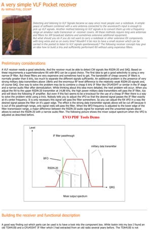
  • 1. A very simple VLF Pocket receiver By Wilfried Fritz, DJ1WF Detecting and listening to VLF Signals became so easy since most people own a notebook. A simple peace of software combined with a wire antenna connected to the soundcard's input is enough to pick up VLF signals. Another method listening to VLF signals is to convert them up into a frequency range an amateur radio transceiver or -receiver covers. All these methods require long wire antennas and filters for AM broadcast stations and sometimes extensive additional equipment. But what should you do if you do not want to carry a notebook or other extensive RX components with long wires and so on every time? Wouldn't it be nice to have a small receiver which can be carried in the pocket to listen to VLF signals spontaneously? The following receiver concept may give an idea how to build a tiny and sufficiently performant RX without using expensive filters. Preliminary considerations A VLF receiver needs a good selectivity. And the receiver must be able to detect CW signals like RSDN-20 and SAQ. Based on these requirements a superheterodyne RX with BFO can be a good choice. The first idea to get a good selectivity is using a very narrow IF filter. But these filters are very expensive and sometimes hard to get. The bandwidth of cheap ceramic IF filters is normally greater than 6 kHz, too much to separate the different signals sufficiently. An additional problem is the presence of very strong military data transmitters above 18kHz and the enormous RF level difference to the relatively weak RSDN-20 signals and, of course SAQ. One way to solve the problem may be to combine a cheap 6 kHz IF filter like CFU455HT or similar in the IF stage and a narrow audio filter after demodulation. While thinking about this idea more detailed, the next problem will occur. When you adjust the RX to the upper RSDN-20 transmitter at 14,88 kHz, the high power military data transmitters will pass the IF filter, too and will block the following IF amplifier. But even if this fact seems to be a knockout for the use of a cheap IF filter there is a way to solve the problem while using a trick. Nobody tells you to adjust the VFO so that the desired signal passes the IF filter exactly at it's center frequency. It is only necessary this signal will pass the filter somewhere. So you can adjust the RX VFO in a way the desired signal passes the filter on it's upper edge. The effect is the strong data transmitter signals above will be cut off because it is out of the passthrogh range, only signal rests will pass the filter. When the BFO frequency is adjusted to the lower edge of the filter transmission range, a major difference between the RSDN-20 audio signal for example and the unwanted signals above allows to extract the RSDN-20 with a narrow audio filter. The following picture shows the mixer output spectrum when the VFO is adjusted as described before. Building the receiver and functional description A good way finding out which parts can be used is to have a look into the component box. While lookin into my box I found an old TDA4100 and a CFU455HT IF filter which I had extracted from an old radio several years before. The TDA4100 is not EVO PDF Tools Demo
  • 2. produced any more, but still available at different suppliers. If you cannot get a TDA4100, an equivalent type A4100D is available. So the construction of the "receiver's heart" and some additional ones to test if the result can be reproduced was no severe problem. The rest of the receiver could be built with common components. The following schematic shows how the receiver works. Click here for full resolution scheme For avoiding the use of a long wire antenna, the first stage is a high impedance preamplifier. With this stage a 30cm telescopic rod antenna is enough to pick up the VLF signals. A longer antenna will improve the signal/noise ratio, but also may cause additional problems. The reason is the increasing RF level which can overdrive the mixer stage when using longer antennas without level compensation. The preamp's output is connected to the TDA4100 mixer input via a potentiometer. This allows to adjust the mixer input level in an optimal way. The advantage in using an AM RX circuit like the TDA 4100 is the presence of a mixer, VFO, IF amplifier and demodulator unit in one integrated circuit. Only a BFO has to be added to hear the CW signals. For keeping it simple, the BFO circuit is built around a 455 kHz ceramic resonator. The frequency tolerance is quite bigger than circuits using a crystal, so the BFO frequency can be changed to several kHz away from the center. In this special case, the BFO oscillates at 452kHz. The complete IF spectrum, BFO signal included, passes the internal IF amplifier. The VFO is included in the TDA 4100. It can be adjusted with a variable capacitor extracted from an old radio or, like in this example, with a varicap diode. The shown dimensions allow to cover a frequency range from 0 to 150kHz, so that higher frequent signals than VLF like time signal and LF-remote control transmitters, LORAN, and DWD Weather fax signals can be picked up with this receiver, too. The demodulated audio signal is available at Pin 19 where an audio low pass filter is connected. Following the audio lowpass, there is an additional audio bandpass filter. The combination of the low- and bandpass-filter supresses the unwanted military data signal rests passing the IF filter in a sufficient way. The last stage is made with a LM 386-1, a very cheap audio amplifier circuit, to drive a small loudspeaker. The circuit can be built in metal or even plastic enclosures. The following picture shows some suggestions. EVO PDF Tools Demo
  • 3. The left receiver was installed into a common Hammond die cast enclosure. The receiver in the middle was built in an old PC loudspeaker housing and the right one was made using a cheap ABS enclosure. It is not necessary to create a PCB, a hole grid board like shown below or even an ugly bug is ok. The only important thing is to take care about proper grounding all over the circuit to avoid oscillaton. An aluminium foil below will reduce the capacitive effects caused by the human hand while holding the receiver. Reception results Even if the circuit is very simple and using cheap filters, the weak RSDN-20 signals can be heard clearly when adjusting the receiver properly. It is necessary to listen in a clean VLF environment. Human made signals coming from switching power supplies and so on may cover the weak signals. Before writing the article, I could not test SAQ reception on 17,2kHz because the signal is very rare. It is only present for some minutes during 2-3 events in the year. But now, I could pick up the SAQ signal during transmissions in summer and winter time with good results. There were some weak interferences from the exorbitant strong data signals beside, but they were much weaker than the desired signals and no problem during listening. EVO PDF Tools Demo
  • 4. For getting an impression how such a receiver can work, I have a uploaded some video clips. Please enter the keywords vlf pocket receiver, maybe with the extension dj1wf into a search engine, and you will get a link to some youtube videos. Thinking about improvements and schematic variations The described receiver is a very simple one, made of cheap parts. It cannot give a performance even God cannot improve. The concept shall give an idea how to build a tiny VLF receiver which can be carried in the pocket for spontaneous VLF listening on several locations. There is much space for own ideas to make the receiver perfect. The described concept is no law how to build a tiny VLF receiver and what parts have to be used. Using AM receiver circuits will simplify the construction, but it is also possible to build a RX even using discrete components. On the other hand, the audio filters also can be built using integrated circuits and so on. As I said, there is a lot of space for own ideas. This circuit works well, but it is not the last spoken word. Following there are some possible ideas how to make the receiver better: 1. The 6 kHz IF filter bandwidth should not be increased, but there may be a way to narrow it. I found out there are 455kHz and 450 kHz IF filters with 6 kHz bandwidth available and still manufactured. If you combine these filters, the overlapping transmission ranges will result in a lower combined bandwidth. When doing this, you will have to pay attention to the resulting transmission attenuation in the passthrough range which may decrease the effect of narrowing the bandwidth a little bit. So an additional IF amplifier stage between the filters may become necessary. 2. The selectivity can be improved by adding a second audio bandpass stage. 3. Maybe it can be a good idea to play with the audio bandpass center frequency. You have to look at the whole system, beginning with the IF filter bandwidth and ending with the loudspeaker's frequency response. 4. A major problem is the audio feedback when adjusting the RX below 5 kHz at high audio levels. This cannot be avoided when concentrating all the parts in a small enclosure combined with high amplification values. So if you need high audio levels without the risk of audio feedback, it may be a way to separate the RX unit and the audio amplifier unit. 5. There is only one additional simple input filter to block strong broadcast stations in the MW range. It consists of a 1mH coil and a 100n capacitor. Combined with the lowpass consisting of the 680k resistors and the FETs internal capacity, that's enough to use the RX in a distance of 10km to a 20kW AM broadcast transmitter on 828kHz without interferences. But in some locations it may become necessary to use additional filters, like choking circuits or similar for suppressing image frequencies from strong AM radio stations in the MW range. 6. When using a varicap VFO adjustment, the tuning voltage has to be stabilized. This is a problem when using small 9V batteries. If you want to cover a frequency range up to 150kHz, a maximum tuning voltage around 6V is necessary. High audio levels will cause a battery voltage breakdown, so that the tuning voltage may breakdown, too. This will cause an unwanted frequency deviation. This can be avoided by using a separate small 12V battery with following voltage stabilisation to 6V. 7. An antenna length around 30cm is very short, but it works. For improving the signal noise ratio, a longer antenna will help. If you use a longer antenna, an additional capacitor in parallel to the FET's Gate will be necessary to avoid strong broadcast signals causing interferences. 8. For better fine tuning the BFO frequency can be made variable. This can be done by removing the ceramic resonator stabilized BFO and using a VCO instead. Or you can perform a fixed value variation by changing the 1,2nF capacitor in the BFO unit into other values. 9. The receiver can be changed quickly into a bat detector when using an ultrasonic microphone instead of the antenna. Such microphones are very rare to get, but some common microphones are sensitive in the ultrasonic range, even if they are specified only up to 22kHz. Maybe it is worth to test it. Conclusions The suggested receiver allows listening to VLF and LF signals in a clean VLF environment without hum. It is made of cheap and common components. A lot of space for own ideas is left. Please be careful when listening to VLF on the open field. Even if the crackling sound of ligthning strokes from all over the world can be heard in the range between 10kHz and 20kHz, it will be a good idea to go home when the crackling becomes louder. An appearing thunderstorm is very dangerous. VLF signals are fascinating, but the human life is fascinating, too. So have fun in picking up VLF signals. Special thanks to Renato for providing his very excellent website. Return to main Index of www.vlf.it EVO PDF Tools Demo