
Recommandé
Recommandé
Contenu connexe
Dernier
Dernier (20)
En vedette
En vedette (20)
Igo50-Product-Guide.pdf
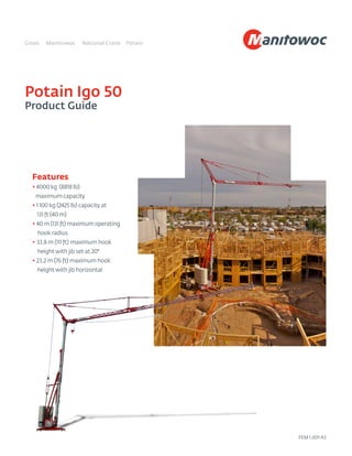
- 1. Potain Igo 50 Product Guide Features • 4000 kg (8818 lb) maximum capacity • 1 100 kg (2425 lb) capacity at 131 ft (40 m) • 40 m (131 ft) maximum operating hook radius • 33,8 m (111 ft) maximum hook height with jib set at 20° • 23,2 m (76 ft) maximum hook height with jib horizontal FEM 1.001-A3
- 2. 2 Features Variable frequency drives Variable frequency drives provide a lower initial current rush and progressive speed change which can be supported by a smaller generator set than comparable cranes. Optional cab Optional fixed height cab and access ladder allows operator to view the job site from a more advantageous position. North American Highway Axle Simplify road transport with the North American High- way Axle and adaptation kit 202. Multiple pin positions for optimal weight distribution, DOT compliance and an optional attachable 3rd axle make this an ideal solution for your transportation needs. Efficiency and reliability The Igo 50 has a simple and quick set up. While onsite, the crane works quietly, reducing interruption to the surrounding area.
- 3. Contents Specifications 4 Transport 5 Dimensions 7 Load charts 8 Crane profile 9 Mechanisms 10 Metric dimensions 11 Metric load charts 12 Metric crane profile 13 Metric mechanisms 14 Symbols glossary 15
- 4. 4 *Denotes optional equipment **Requires optional anemometer Specifications Jib 40 m (131 ft) radius standard bi-folding offsettable lattice jib. Removable jib extensions can allow additional horizontal jib operating radii of 28 m (92 ft) or 36 m (118 ft).Two (2) tie bar lines with adjustable lengths allow jib to be offset 8˚ and 20˚. Folds to 14 m (46 ft) radius or 29,6 m (97 ft) radius. Two (2) erecting speeds controlled from the remote, opening and aligning are carried out automatically by two (2) hydraulic cylinders. Galvanized folding mast with hydraulic cylinder for erection. Two (2) erecting speeds controlled from the remote. No locking necessary. 360˚ rotation possible during erection. Outriggers swing and lock into position. 4,5 m (14.8 ft) square outrigger spread with 2,5 m (8.2 ft) slewing radius. Level bubble integrated into the chassis. Outrigger pads are stowed on the crane during transport (540 x 410 mm [21 in x 16 in]). *Optional outrigger pads available at heights of 200 mm (7.9 in) and 400 mm (15.7 in). 5640 kg (12,434 lb) concrete ballast standard. Crane with standard ballast is able to be transported on several *axle sets. *Additional 22 800 kg (50,268 lb) concrete ballast optional. 480 volt, 60 Hz measured at the turntable. Earth rod and electric cable stowed on the crane during transport. SM/DM block for 2 or 4-part line. One pin removal to change between SM and DM. Pure SM1 (section of hook block removed) is possible with gain of 100 kg (220 lb) lifting capacity. Wireless remote control provides information to the operator about **wind speed, radius, hook height, load, and moment. Lights and buzzers alert the operator when nearing limits of operation. Auxiliary remote attached by umbilical cord ensures continual operation in case of battery or other malfunction of the wireless remote control. Electronic wind speed meter to alert the operator of wind speed conditions. Provides selective display on the radio remote. Maximum in service wind speed is 72 km/h (45 mph) and maximum out of service wind speed is 150 km/h (93 mph). RVF 51 Optima+ slewing mechanism with maximum swing speed of 0.8 RPM. Progressive control of speed with counter-slewing possible, anti-load swinging system makes aligning the load and jib easier. Multiple RPM speeds possible depending upon parameter selected. 15 LVF 10 Optima: 15 HP variable frequency hoist with 1t (1.1 USt) line pull. 3 notch, progressive speed change according to the accelerating or decelerating ramps. Optima allows the hoist to adapt its speed to the weight of the load. 3 DVF 5: 3 HP variable frequency hoist with 500 kg (1102 lb) line pull. 2 notch winch, progressive speed change according to acceleration or deceleration ramps controlled by the frequency converter. Four (4) cylinders and two (2) pumps linked to solenoid valves. Two (2) cylinders for unfolding the jib, one (1) for slewing the derrick, and one (1) for raising the mast. * STANDARD NORTH AMERICAN SPECIFICATION: includes hydraulic ballasting derrick, high sole plates, Dialog Wind, 12 concrete counterweight slabs, pre-equipment for interference system and Top Zone. * High sole plates * Fixed height cab and access ladder * Transport axles and kits * Top Zone * Top Tracing * Dialog Wind Mast Chassis *Ballast Electrical requirement Reeving *Optional Anemometer Controls Swing Hoist Trolley Hydraulic equipment *Optional equipment Uses the hoisting winch to ballast the crane or dismantle/attach *fifth-wheel. Stows alongside the jib during transport. Optional hydraulic ballasting derrick Axle sets are available for both jobsite and highway applications. Jobsite axles are rated at either 10 kph (6 mph) or 25 kph (15.5 mph); highway axle set is rated at 80 kph (50 mph). *Optional transport axle sets
- 5. 5 Potain Igo 50 NOTE: Dimensions and weights may vary due to manufacturing tolerances. Transport 13,98 m (45.9 ft) P2 P P1 15,41 m (50.6 ft) 13,98 m (45.9 ft) 5,24 m (17.2 ft) 5,88 m (19.3 ft) 3,65 m (12 ft) 0,7 m (2.3 ft) 1,25 m (4.1 ft) 4 m (13.1 ft) 2,5 m (8.2 ft) 2,45 m (8 ft) P2 P P1 16,39 m (53.8 ft) 5,87 m (19.3 ft) 5,25 m (17.2 ft) 2,75 m (9 ft) Max: 3,57 m (11.7 ft) Min: 3,42 m (11.2 ft) Max: 0,35 m (1.1 ft) Min: 0,2 m (0.7 ft) 2,5 m (8.2 ft) 2,4 m (7.9 ft) DJ100 / S120 10 km/h (6 mph) SL122 / J215M 80 km/h (50 mph) P2 P P1 15,41 m (50.6 ft) 13,98 m (45.9 ft) 6,19 m (20.3 ft) 4,93 m (16.2 ft) 3,65 m (12 ft) 0,7 m (2.3 ft) 1,25 m (4.1 ft) 4 m (13.1 ft) 2,5 m (8.2 ft) 2,45 m (8 ft)
- 6. 6 NOTE: Dimensions and weights may vary due to manufacturing tolerances. Transport Chassis data (in transport position) DJ100/S120 25 kph (15.5 mph) SL122/J215M 80 kph (50 mph) North American Highway Axle meters feet meters feet meters feet Overall length 16,39 53.8 15,41 50.6 15,41 50.6 Overall height Max: 3,57 Min: 3,42 Max: 11.7 Min: 11.2 4 13.1 4 13.1 Overall width 2,5 8.2 2,5 8.2 2,6 8.2 Overhang 5,87 19.3 6,19 20.3 TBA TBA North American Highway Axle Weights Crane weight less counterweight 14 760 kg 32,540 lb Counterweight for operation 28 440 kg 62,700 lb Crane with counterweight 43 240 kg 95,328 lb Crane with transport equipment DJ100/S120 25 kph (15.5 mph) SL122/J215M 80 kph (50 mph) North American Highway Axle In transport with minimal counterweight: kilograms pounds kilograms pounds kilograms pounds Gross (P) 21 655 47,741 23 650 52,139 TBA TBA Rear (P1) 11 725 25,849 15 400 33,951 TBA TBA Front (P2) 9930 21,892 8250 18,188 TBA TBA Counterweight in transport (2 blocks): 5640 12,434 5640 12,434 TBA TBA *Other axle sets are available. 15,41 m (50.6 ft) 13,98 m (45.9 ft) 2,5 m (8.2 ft) 2,6 m (8.5 ft) 1,25 m (4.1 ft) 4 m (13.1 ft) 3,65 m (12 ft) TBA TBA P1 P P2 0,7 m (2.3 ft)
- 7. 131 ft 76 ft 2 1 1400 kg 118 ft 97 ft 4409 lb 52 ft 46 ft 14.8 ft x 14.8 ft 16.7 ft 86 ft R = 8.2 ft 5.7 ft 8818 lb 92 ft 46 ft 4.6 ft 2 47 ft 1 8818 lb 43 ft 9.8 ft 68 ft 70 ft 73 ft 3748 lb 8818 lb 8818 lb 73 ft 2425 lb 75 ft 3086 lb 7 Potain Igo 50 Dimensions THIS CHART IS ONLY A GUIDE AND SHOULD NOT BE USED TO OPERATE THE CRANE. The individual crane’s load chart, operating instructions and other instructional plates must be read and understood prior to operating the crane F1 F1 30.3 USt 23.9 USt 32,540 lb 62,702 lb (2 x 6217 lb + 12 x 4189 lb)
- 8. 8 Load charts THIS CHART IS ONLY A GUIDE AND SHOULD NOT BE USED TO OPERATE THE CRANE. The individual crane’s load chart, operating instructions and other instructional plates must be read and understood prior to operating the crane. 131 ft 10 74 78 82 89 98 105 115 121 130 ft 4409 4134 3924 3571 3131 2888 2579 2403 2205 lb 4409 4189 3825 3373 3131 2811 2624 2425 lb 118 ft 10 82 86 89 98 105 115 117 ft 4409 4167 4023 3549 3274 2932 2866 lb 4409 4266 3770 3494 3153 3086 lb 92 ft 10 91 ft 4409 lb 4409 lb 131 ft 10 80 84 89 96 ft 118 ft 4409 4167 3902 3527 lb 4409 4123 3748 lb 131 ft 118 ft 10 46 ft 92 ft 4409 lb 4409 lb 10 43 46 49 52 56 59 62 66 75 79 82 89 98 105 115 121 131 ft 8818 8080 7419 6845 6360 5930 5556 5214 4409 4134 3968 3616 3175 2932 2612 2436 2205 lb 4409 4134 3968 3616 3175 2932 2612 2436 2205 lb 4409 4233 3869 3417 3164 2844 2668 2425 lb 10 47 49 52 56 59 62 66 72 79 83 87 89 98 105 115 118 ft 8818 8311 7683 7132 6658 6239 5864 5225 4707 4409 4167 4079 3594 3318 2965 2866 lb 4409 4167 4079 3594 3318 2965 2866 lb 4409 4321 3825 3549 3197 3086 lb 10 52 56 59 62 66 72 75 82 85 89 92 ft 8818 8014 7485 7011 6592 5886 5578 5049 4828 4608 4409 lb 4409 lb 4409 lb 131 ft 10 46 49 52 56 59 62 66 72 81 82 85 89 97 ft 118 ft 8818 8058 7441 6911 6449 6041 5677 5060 4409 4332 4167 3946 3527 lb 4409 4332 4167 3946 3527 lb 4409 4178 3748 lb 131 ft 10 46 ft 8818 lb 4409 lb 4409 lb 118 ft 10 46 ft 8818 lb 4409 lb 4409 lb 92 ft 10 46 ft 8818 lb 4409 lb 4409 lb 131 ft 10 123 ft 2205 lb 2425 lb 118 ft 10 111 ft 2205 lb 2425 lb 92 ft 10 87 ft 2205 lb 2425 lb 131 ft 10 92 ft 118 ft 2205 lb 2425 lb 131 ft 118 ft 10 44 ft 92 ft 2205 lb 2425 lb 2425 lb 118 ft 92 ft 131 ft 3086 lb 4409 lb 8818 lb 46 ft 3748 lb 97 ft 8° 3748 lb 96 ft 80 ft 117 ft 3086 lb 83 ft 2425 lb 86 ft 130 ft 46 ft 4409 lb 72 ft 4409 lb 91 ft 79 ft 20° 111 ft 123 ft 2425 lb 111 ft 2425 lb 106 ft 92 ft 2425 lb 98 ft 44 ft 2425 lb 80 ft 87 ft 2425 lb 97 ft
- 9. 9 Potain Igo 50 Crane profile THIS CHART IS ONLY A GUIDE AND SHOULD NOT BE USED TO OPERATE THE CRANE. The individual crane’s load chart, operating instructions and other instructional plates must be read and understood prior to operating the crane 125 ft 20 13 7 0 7 13 20 26 33 39 46 52 59 66 72 79 85 92 98 105 112 118 125 131 138 ft 7 13 20 26 33 39 46 52 59 66 72 79 85 92 98 105 112 118 0 ≤ 31 mph Igo 50: Raised jibs 20 13 7 0 7 13 20 26 33 39 46 52 59 66 72 79 85 92 98 105 118 131 ft 131 ft 125 118 112 105 98 92 85 79 72 66 59 52 46 39 33 26 20 13 7 0 Jib raised 20° 123ft 111ft 92ft 87ft 44 ft 10ft 20° 80ft 97ft 98ft 106ft 111ft 20 13 7 0 7 13 20 26 33 39 46 52 59 66 72 79 85 92 98 105 118 131 ft 131 ft 125 118 112 105 98 92 85 79 72 66 59 52 46 39 33 26 20 13 7 0 8° 86 ft 130 ft 117 ft 91 ft 96 ft 46 ft 83 ft 80 ft 79 ft 72 ft 9.8ft Jib raised 8°
- 10. 10 Mechanisms THIS CHART IS ONLY A GUIDE AND SHOULD NOT BE USED TO OPERATE THE CRANE. The individual crane’s load chart, operating instructions and other instructional plates must be read and understood prior to operating the crane. 15 LVF 10 Optima IEC 60204-32 400 V (+10% -10%) 50 Hz / 480 V (+6% -10%) 60 Hz 17 kVA 19 kVA 4409 lb +25 % 1102 2205 fpm 0 218 167 102 0 480 V - 60 Hz hp kW 15 LVF 10 Optima ft/min 12 59 102 167 218 6 30 51 84 108 15 11 lb 4409 4409 4409 2205 1102 8818 8818 8818 4409 2205 3 DVF 5 ft/min 49 - 98 - 148 (0 2205 lb) 49 - 98 - 135 (2205 8818 lb) 3 2.2 RVF 51 Optima+ rpm 0 0.8 5.5 4
- 11. 11 Potain Igo 50 Metric dimensions THIS CHART IS ONLY A GUIDE AND SHOULD NOT BE USED TO OPERATE THE CRANE. The individual crane’s load chart, operating instructions and other instructional plates must be read and understood prior to operating the crane 40 m 23,2 m 2 1 1400 kg 36 m 29,6 m 2000 kg 15,7 m 14 m 4,5 m x 4,5 m 5,09 m 26,3 m R = 2,5 m 1,75 m 4000 kg 28 m 13,9 m 1,4 m 2 14,3 m 1 4000 kg 13 m 3 m 20,8 m 21,3 m 22,4 m 1700 kg 4000 kg 4000 kg 22,3 m 1100 kg 22,9 m 1400 kg F1 F1 27,5 t 21,7 t 14 760 kg 28 440 kg (2 x 2820 kg + 12 x 1900 kg)
- 12. 12 Metric load charts THIS CHART IS ONLY A GUIDE AND SHOULD NOT BE USED TO OPERATE THE CRANE. The individual crane’s load chart, operating instructions and other instructional plates must be read and understood prior to operating the crane. 40 m 3 22,7 23,9 25 27 30 32 35 37 39,6 m 2000 1875 1780 1620 1420 1310 1170 1090 1000 kg 2000 1900 1735 1530 1420 1275 1190 1100 kg 36 m 3 25,1 26,3 27 30 32 35 35,6 m 2000 1890 1825 1610 1485 1330 1300 kg 2000 1935 1710 1585 1430 1400 kg 28 m 3 27,7 m 2000 kg 2000 kg 40 m 3 24,4 25,5 27 29,3 m 36 m 2000 1890 1770 1600 kg 2000 1870 1700 kg 40 m 36 m 3 13,9 m 28 m 2000 kg 2000 kg 3 13 14 15 16 17 18 19 20 23 24,2 25 27 30 32 35 37 40 m 4000 3665 3365 3105 2885 2690 2520 2365 2000 1875 1800 1640 1440 1330 1185 1105 1000 kg 2000 1875 1800 1640 1440 1330 1185 1105 1000 kg 2000 1920 1755 1550 1435 1290 1210 1100 kg 3 14,3 15 16 17 18 19 20 22 24 25,3 26,6 27 30 32 35 36 m 4000 3770 3485 3235 3020 2830 2660 2370 2135 2000 1890 1850 1630 1505 1345 1300 kg 2000 1890 1850 1630 1505 1345 1300 kg 2000 1960 1735 1610 1450 1400 kg 3 15,7 17 18 19 20 22 23 25 26 27 28 m 4000 3635 3395 3180 2990 2670 2530 2290 2190 2090 2000 kg 2000 kg 2000 kg 40 m 3 13,9 15 16 17 18 19 20 22 24,7 25 25,8 27 29,6 m 36 m 4000 3655 3375 3135 2925 2740 2575 2295 2000 1965 1890 1790 1600 kg 2000 1965 1890 1790 1600 kg 2000 1895 1700 kg 40 m 3 14 m 4000 kg 2000 kg 2000 kg 36 m 3 14 m 4000 kg 2000 kg 2000 kg 28 m 3 14 m 4000 kg 2000 kg 2000 kg 40 m 3 37,6 m 1000 kg 1100 kg 36 m 3 33,9 m 1000 kg 1100 kg 28 m 3 26,4 m 1000 kg 1100 kg 40 m 3 27,9 m 36 m 1000 kg 1100 kg 40 m 36 m 3 13,4 m 28 m 1000 kg 1100 kg 1100 kg 36 m 28 m 40m 1400 kg 2000 kg 4000 kg 14 m 1700 kg 29,6 m 8° 1700 kg 29,3 m 24,4 m 35,6 m 1400 kg 25,4 m 1100 kg 26,2 m 39,6 m 13,9 m 2000 kg 22 m 2000 kg 27,7 m 24,2 m 20° 33,8 m 37,6 m 1100 kg 33,9 m 1100 kg 32,2 m 27,9 m 1100 kg 29,8 m 13,4 m 1100 kg 24,5 m 26,4 m 1100 kg 29,6 m
- 13. 13 Potain Igo 50 Metric crane profile THIS CHART IS ONLY A GUIDE AND SHOULD NOT BE USED TO OPERATE THE CRANE. The individual crane’s load chart, operating instructions and other instructional plates must be read and understood prior to operating the crane Igo 50: Raised jibs 38 m 6 4 2 0 2 4 6 8 10 12 14 16 18 20 22 24 26 28 30 32 34 36 38 40 42 m 2 4 6 8 10 12 14 16 18 20 22 24 26 28 30 32 34 36 0 ≤ 50 km/h 6 4 2 0 2 4 6 8 10 12 14 16 18 20 22 24 26 28 30 32 34 36 38 40 42 m 40 m 38 36 34 32 30 28 26 24 22 20 18 16 14 12 10 8 6 4 2 0 Jib raised 20° 37,6m 33,9m 27,9m 26,4m 13,4m 3m 20° 24,5m 29,6m 29,8m 32,2m 33,8m 6 4 2 0 2 4 6 8 10 12 14 16 18 20 22 24 26 28 30 32 34 36 38 40 42 m 40 m 38 36 34 32 30 28 26 24 22 20 18 16 14 12 10 8 6 4 2 0 8° 26,2 m 39,6 m 35,6 m 27,7 m 29,3 m 13,9 m 25,4 m 24,4 m 24,2 m 22 m 3m Jib raised 8°
- 14. 14 Metric mechanisms THIS CHART IS ONLY A GUIDE AND SHOULD NOT BE USED TO OPERATE THE CRANE. The individual crane’s load chart, operating instructions and other instructional plates must be read and understood prior to operating the crane. 15 LVF 10 Optima IEC 60204-32 400 V (+10% -10%) 50 Hz / 480 V (+6% -10%) 60 Hz 17 kVA 19 kVA 2000 kg +25 % 500 1000 m/min 0 66,5 51 31 0 480 V - 60 Hz hp kW 15 LVF 10 Optima m/min 3,6 18 31 51 66,5 1,8 9 15,5 25,5 33 15 11 kg 2000 2000 2000 1000 500 4000 4000 4000 2000 1000 3 DVF 5 m/min 15 - 30 - 45 (0 1000 kg) 15 - 30 - 41 (1000 4000 kg) 3 2,2 RVF 51 Optima+ rpm 0 0,8 5,5 4
- 15. 15 Potain Igo 50 Symbols glossary Anemometer Ballast Chassis Controls Hydraulic equipment Electrical equipment Hoisting Jib Mast Consult us Optional transport axle sets Options Reactions in service Reactions out of service Reeving Required power Slewing Standard equipment Total ballast weight Trolleying Weight without load, without ballast, without transport axles, with max. jib and standard height Slewing radius Optional hyrdaulic ballasting derrick R Reeving 2-part Reeving 4-part
- 16. ©2014 Manitowoc Form No. Igo 50 PG Part No. 04-029-1M-0814 www.manitowoccranes.com This document is non-contractual. Constant improvement and engineering progress make it necessary that we reserve the right to make specification, equip- ment, and price changes without notice. Illustrations shown may include optional equipment and accessories and may not include all standard equipment. Regional offices China Shanghai, China Tel: +86 21 6457 0066 Fax: +86 21 6457 4955 Greater Asia-Pacific Singapore Tel: +65 6264 1188 Fax: +65 6862 4040 Europe, Middle East, Africa Dardilly, France Tel: +33 (0)4 72 18 20 20 Fax: +33 (0)4 72 18 20 00 Americas Manitowoc,Wisconsin, USA Tel: +1 920 684 6621 Fax: +1 920 683 6277 Shady Grove, Pennsylvania, USA Tel: +1 717 597 8121 Fax: +1 717 597 4062 Regional headquarters Manitowoc Cranes China Beijing Chengdu Guangzhou Xian Greater Asia-Pacific Australia Brisbane Melbourne Sydney India Chennai Delhi Hyderabad Pune Korea Seoul Philippines Makati City Singapore Factories Brazil Passo Fundo China TaiAn Zhangjiagang France Charlieu Moulins Germany Wilhelmshaven India Pune Italy Niella Tanaro Portugal Baltar Fânzeres USA Manitowoc Port Washington Shady Grove Americas Brazil Alphaville Mexico Monterrey Chile Santiago Europe, Middle East, Africa France Baudemont Cergy Decines Germany Langenfeld Italy Lainate Netherlands Breda Poland Warsaw Portugal Baltar Russia Moscow South Africa Johannesburg U.A.E. Dubai U.K. Buckingham