1. 1
Digital Design(Mano-5) Notes: Chapter 1
Digital Design (Mano) Chapter 1 Notes
Digital systems manipulate discrete quantitiesof information that are represented in binary form. Operands used for calculat ions may be
expressedinthe binarynumber system. Other discrete elements, including the decimal digits andcharacters ofthe alphabet, are represented in
binary codes.
Digital circuits, alsoreferredto as logic circuits, process data bymeans of binarylogic elements (logic gates) usingbinary signals. Quantities are
stored in binary (two‐valued) storage elements (flip‐flops).
The decimal number system is saidto be of base, or radix, 10 because it uses 10 digits and the coefficients are multiplied by po wers of 10. The
binary system is a different number system.
The radix point (e.g., the decimal point when 10 is the radix) distinguishes positive powers of 10 from negative powers of 10.
In computer work, 210 is referred to as K (kilo), 220 as M (mega), 230 as G (giga), and 240 as T (tera). Thus, 4K = 212 = 4,096 and 16M = 224 =
16,777,216.
For binarysubtraction, The rulesare still the same as indecimal, except that the borrowina givensignificant positionadds 2 to a minuenddigit. (A
borrow in the decimal system adds 10 to a minuend digit.)
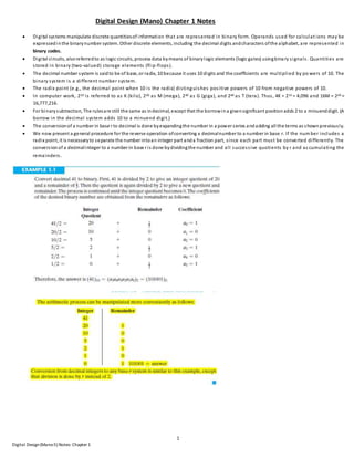
The conversionof a number in base r to decimal is done byexpandingthe number in a power series andadding all the terms as shownpreviously.
We now present a general procedure for the reverse operation ofconverting a decimalnumber to a number in base r. If the num ber includes a
radix point, it is necessaryto separate the number intoan integer part anda fraction part, since each part must be converted differently. The
conversionof a decimalinteger to a number in base r is done bydividingthe number and all successive quotients by r and accumulating the
remainders.
2. 2
Digital Design(Mano-5) Notes: Chapter 1
The conversionfrom binaryto octal is easilyaccomplished bypartitioning the binarynumber intogroups of three digits each, starting fromthe binarypoint
and proceeding to the left andto the right.
3. 3
Digital Design(Mano-5) Notes: Chapter 1
One scheme that retains the binarysysteminthe
computer, but reducesthe number ofdigits the
humanmust consider, utilizes the relationship
betweenthe binarynumber systemandthe octal or
hexadecimalsystem. Bythis method, the human
thinks interms ofoctal or hexadecimal numbers and
performs the required conversion byinspectionwhen
direct communicationwith the machine is necessary.
Thus, the binarynumber 111111111111 has 12 digits
and is expressed inoctal as 7777 (4 digits)or in
hexadecimalas FFF (3 digits). Duringcommunication
betweenpeople (about binarynumbers inthe
computer), the octal or hexadecimalrepresentationis
more desirable because it can be expressed more
compactlywith a thirdor a quarter of the number of
digits requiredfor the equivalent binarynumber.
Thus, most computer manuals use either octal or
hexadecimalnumbers to specifybinaryquantities.
5. 5
Digital Design(Mano-5) Notes: Chapter 1
When arithmetic operations are implemented ina computer, it is more convenient to use a different system, referredto as the signedcomplement
system, for representingnegative numbers. Inthis system, a negative number is indicatedbyits complement. Whereas the signed‐magnitude
systemnegatesa number bychangingits sign, the signed‐complement system negates a number bytaking its complement. Since p ositive numbers
always start with 0 (plus) inthe leftmost position, the complement will always start witha 1, indicating a negative number. The signed‐
complement system canuse either the 1’s or the 2’s complement, but the 2’s complement is the most common. As an example, consider the
number 9, representedinbinarywith eight bits. +9 is representedwith a signbit of 0 inthe leftmost position, followed by the binaryequivalent of
9, which gives 00001001. Note that all eight bits must have a value; therefore, 0’s are insertedfollowingthe signbit up to the first 1. Although
there is onlyone wayto represent +9, there are three different ways to represent -9 witheight bits:
signed‐magnitude representation: 10001001
signed‐1’s‐complement representation: 11110110
signed‐2’s‐complement representation: 11110111
In signed‐magnitude, -9 is obtainedfrom +9 bychangingonlythe signbit in the leftmost position from0 to 1. In signed‐1’s-complement, -9 is
obtained bycomplementing all the bits of +9, includingthe sign bit. The signed‐2’s‐complement representationof -9 is obtainedbytakingthe 2’s
complement of the positive number, including the signbit.
Table 1.3 lists all possible four‐bit signedbinarynumbers inthe three representations. The equivalent decimal number is also shown for reference.
Note that the positive numbers in all three representations are identical andhave 0 in the leftmost position. The signed‐2’s‐complement system
has onlyone representationfor 0, which is always positive. The other twosystems have either a positive 0 or a negative 0, something not
encountered in ordinaryarithmetic. Note that allnegative numbers have a 1 inthe leftmost bit position;that is the waywe distinguishthemfrom
the positive numbers. Withfour bits, we can represent 16 binarynumbers. In the signed‐magnitude andthe 1’s‐complement representations,
there are eight positive numbers and eight negative numbers, including twozeros. Inthe 2’s‐complement representation, there are eight positive
numbers, includingone zero, and eight negative numbers.
6. 6
Digital Design(Mano-5) Notes: Chapter 1
The signed‐magnitude system is usedinordinaryarithmetic, but is awkward when employedincomputer arithmetic because of th e separate
handling of the signandthe magnitude. Therefore, the signed‐complement system is normallyused. The 1’s complement imposes some difficulties
and is seldom usedfor arithmetic operations. It is useful as a logical operation, since the change of 1 to 0 or 0 to 1 is eq uivalent to a logical
complement operation, as willbe showninthe next chapter. The discussionof signedbinaryarithmetic that follows deals exclusivelywiththe
signed‐2’s‐complement representationof negative numbers. The same procedures canbe applied to the signed‐1’s‐complement systemby
includingthe end‐aroundcarryas is done withunsignednumbers.
*** 11111001 shows that sign extensiondoesn’t workfor sign-magnitude representationof negative numbers
7. 7
Digital Design(Mano-5) Notes: Chapter 1
**The following is onlyfor total clarityregardingsubtraction in complement form. Else the onlyrelevant to be notedfrom belowis that incomplement
form, it’s onlyaddition that we are doing. The below content justifieswhyaddition inthis case is essentiallythe same as generalsubtraction.Belowcontent
can be readinsecondrun or later:
BINARY CODES (Can be skippedas reference.Easyand cool though; Gray/ASCII/Error-correcting have beenleftout):
Anydiscrete element ofinformationthat is distinct among a groupof quantitiescanbe representedwitha binarycode (i.e., a patternof 0’s and
1’s). The codesmust be inbinarybecause, in today’s technology, onlycircuits that represent andmanipulate patterns of 0’s and 1’s canbe
8. 8
Digital Design(Mano-5) Notes: Chapter 1
manufacturedeconomicallyfor use incomputers. However, it must be realizedthat binarycodes merelychange the symbols, not the meaning of
the elements of information that theyrepresent. If we inspect the bits of a computer at random, we will findthat most of the time theyrepresent
some type of codedinformationrather thanbinarynumbers.
Although the minimumnumber of bits required to code 2n distinct quantitiesis n, there is nomaximum number of bits that may be used for a
binarycode. For example, the 10 decimal digits can be codedwith10 bits, andeachdecimal digit canbe assigneda bit combinationof nine 0’s and
a 1. In this particular binarycode, the digit 6 is assignedthe bit combination0001000000.
Binary-coded Decimal Code: Although the binarynumber system is the most natural systemfor a computer because it is readilyrepresentedin
today’s electronic technology, most people are more accustomed to the decimal system. One wayto resolve this difference is to convert decimal
numbers to binary, perform all arithmetic calculations inbinary, and thenconvert the binaryresults backto decimal. Thismethod requires that we
store decimal numbers inthe computer sothat theycanbe converted to binary. Since the computer canaccept onlybinaryvalues, we must
represent the decimal digits bymeans of a code that contains 1’s and0’s. It is also possible to perform the arithmetic operations directlyon
decimal numbers whentheyare storedinthe computer in codedform.
A binarycode will have some unassigned bit combinations ifthe number of elements inthe set is not a multiple power of 2. The 10 decimal
digits form such a set. A binarycode that distinguishes among10 elements must contain at least four bits, but 6 out of the 16 possible
combinations remain unassigned. Different binarycodes canbe obtained byarrangingfour bits into10 distinct combinations. The code most
commonlyusedfor the decimal digits is the straight binaryassignment listed inTable 1.4 . This scheme is called binary‐coded decimal and is
commonlyreferred to as BCD. Other decimal codes are possible anda few ofthem are presentedlater inthis section.
It is obvious that the representationof a BCD number needs more bits thanits equivalent binaryvalue. However, there is anadvantage inthe use
of decimal numbers, because computer input and output data are generatedbypeople who use the decimal system.
12. 12
Digital Design(Mano-5) Notes: Chapter 1
Binary Logic: Dot or no symbol for AND, + for OR, Bar or apostrophe for Negation/complement.
Logic Gates:
o AND and OR gates canhave more thantwo inputs, NOT gate or inverter hasone input (which itself can be a result of AND/OR ga tes).
o Logic gates are electronic circuits that operate onone or more input signals to produce an output signal. Electrical signals such as
voltages or currents exist as analog signalshavingvalues over a given continuous range, say, 0 to 3 V, but in a digital sys tem these
voltages are interpretedto be either of tworecognizable values, 0 or 1. Voltage‐operatedlogic circuits respond to twoseparate voltage
levels that represent a binaryvariable equal to logic 1 or logic 0. For example, a particular digital system maydefine logi c 0 as a signal
equal to 0 V and logic 1 as a signal equal to 3 V. In practice, each voltage level has anacceptable range, as shown in Fig. 1.3 . The input
terminals of digitalcircuits accept binarysignals withinthe allowable range and respondat the output terminals withbinarysignals that
fall withinthe specified range. The intermediate regionbetweenthe allowed regions is crossed only during a state transition. Any
desiredinformationfor computing or control can be operatedon bypassing binarysignals through various combinations of log ic gates,
with eachsignal representinga particular binaryvariable. When the physicalsignal is ina particular range it is interpretedto be either a 0
or a 1.