SlideShare une entreprise Scribd logo
1  sur  7
Mimi Madihah Bt Mohd Idris                    1061110400

Development of an internet controlled surveillance mobile robot.

Weekly report
Week 5

For this week, doing some literature review about Development of an internet controlled
surveillance mobile robot. By reading some of the research paper gives some valuable
information to improve the project more. Until now, there were two research papers, the first
paper is Internet Control of a Domestic Robot Using a Wireless Lan and the second papers
are An Efficient Localization Scheme for an Indoor Mobile Robot.

Some comparison can be make between this two research paper, the first paper write a lot about
the connection involved to controlled the robot. But for the second paper, writes a lot about the
using of RFID that act a sensor to control the robot.

Multifunctional Mobile Robot offers four types of option to be added on it. The types are Line
detection, distance measure using Ultrasonic, Distance measuring using analog sensor and finally
controlled wirelessly using SKXBEE.

The line detection is using four pairs of IR sensors which will be attached to the bottom of the
robot. These 4 sensors will be classified as left sensor, middle left sensor, middle right sensor
and right sensor. A view of the placement of the sensors is as below:
The distance between 2 sensors depends on the width. The sensor should be placed in such a way
that maximum distance of two sensors is equal to the width of the line as shown in figure below.


To teach the robot for line detection, user may follow these steps:


1. Adjust the robot so that the center infrared sensor is on top of white floor; make sure the
wheels and castor of the robot touches the floor properly.
2. Use the screw driver to adjust the preset of center sensor until indicator LED (center) light
ON.
3. Now adjust the robot to move the center sensor towards the black line where the reflection of
infrared is poor.
4. At this point, make sure the indicator LED is OFF. If the LED is still on, it means user has
over tune the preset. Tune it back so that the indicator is OFF.
5. Repeat step 1 - 4 for a few time and make sure the indicator LED ON and OFF correctly at the
right spot.
6. Repeat step 1 - 5 to "teach" left sensor and right sensor.
How the sensors function when the robot follows a black line on a white floor:


This is the concept of a line following robot. We can see that when the middle sensor detects the
line, the robot will move forward. This is because the line is in the center of the robot. But when
the left sensor or the right sensor detects the black line, this means that the robot have strayed
from the line. If the robot strayed to the right, the left sensor will detect the line and the brain will
react by turning left to go back to the line. As for the right sensor, it reacts in the opposite way.


After going through the user’s manual, and the programming code, the line detection only works
well when the robot detected black line on white floor. This is because the sensor itself only for
detecting black and white. To change the choices of the color is depends on the sensor color that
the robot use. For this project, the robot is using white and black sensor for the line detection.
Week 6

Discussing about the location for the spy camera so that the view is clear enough to be view from
the laptop. Read some information how the Xbee works and how to use it on the Multifunctional
Mobile Robot. Some step need to be done first before the both can work well together. The first
step is to test the both Xbee with two laptops. After the both Xbee communicate, then one of the
Xbee ready to put on the Multifunctional Mobile Robot.

Some problem occurs when the Xbee on the Multifunctional Mobile Robot does not
communicate with other Xbee. So some research needs to be done in order this problem can be
solved immediately. Looking at the programming, it seem have some error occurs. So after
contact the technical department, they found that some error in the programming and they upload
the correct programming that works well with Xbee.

Xbee Pro offers indoor communication range up to 100m and outdoor line of sight range up to
1500m.The both Xbee Pro works well with each other with that range by using computer. For
this project, both Xbee Pro are using for controlling the Multifunctional Mobile using the
keyboard, one Xbee Pro will be located at the computer and the other one will be located on
Multifunctional Mobile Robot. The user may control the robot using Num pad 8 to move
forward, 4 to turn left, 6 to turn right, and 2 to move backward.
Below is the example of programming code for Xbee part:
//Mode 4 : Xbee
// Description : Control the robot using UART ( XBEE or an UART wireless module.
//============================================================================================
================
void wireless_xbee (void)
{
        lcd_clr();
                                                  // clear the lcd
        while(1)
                                                  // looping forever
        {
                     lcd_goto (0);


                     if (data[0] == 100)
                                                  // check if UART start byte is met
                     {
                              send_string(" XBEE CONTROL ");
                     // display string
                              SPEEDL = 200;
                                                  // set the motor speed
                              SPEEDR = 200;
                              while(1)
                              {
                                         lcd_goto(20);
                                         if (RCREG == '8')
                                                  // if character '8' is detected, the robot move forward
                                         {
                                                  forward();
                                                  send_string("FORWARD         ");
                                         }


                                         else if (RCREG == '2')
                                                  // if character '2' is detected, the robot move backward
                                         {
backward();
                           send_string("BACKWARD           ");
                  }
                  else if (RCREG == '6')
                           // if character '6' is detected, the robot turn right
                  {
                           right();
                           send_string("TURN RIGHT        ");
                  }


                  else if (RCREG == '4')
                           // if character '4' is detected, the robot turn left
                  {
                           left();
                           send_string("TURN LEFT        ");
                  }


                  else if (RCREG == '5')
                           // if character '5' is detected, then stop the robot
                  {
                           stop();
                           send_string("INVALID COMMAND ");
                  }


                  else
                                              // else then stop the robot
                  {
                           stop();
                           send_string("INVALID COMMAND ");
                  }
           }
    }
    else   send_string("COMMAND");
}
Week 7
For this week, the Multifunctional Mobile Robot experiments have been done. The experiment
was done at the MMU building such as hostel and FCM. The robot was test under certain level
especially the range of the robot. This is because the robot will be communicating wirelessly
using Xbee Pro that can be operating at certain range. At the hostel area, the robot was able to
operate at three storey building under the keyboard controlled. For the spy camera, from the
description of the spy camera says that the range only up to 100m.The experiment done at hostel
building, the spy camera was able to view the video up to three storey building. The results give
a brief view how well the robot will work.

Contenu connexe

Similaire à Weekly Report 5 7

Write a C++ program which generates and displays a random walk acros.pdf
Write a C++ program which generates and displays a random walk acros.pdfWrite a C++ program which generates and displays a random walk acros.pdf
Write a C++ program which generates and displays a random walk acros.pdfmckenziecast21211
 
Arduino Final Project
Arduino Final ProjectArduino Final Project
Arduino Final ProjectBach Nguyen
 
The bytecode hocus pocus - JavaOne 2016
The bytecode hocus pocus - JavaOne 2016The bytecode hocus pocus - JavaOne 2016
The bytecode hocus pocus - JavaOne 2016Raimon Ràfols
 
The bytecode mumbo-jumbo
The bytecode mumbo-jumboThe bytecode mumbo-jumbo
The bytecode mumbo-jumboRaimon Ràfols
 
Omnidirection Robot 3-wheel
Omnidirection Robot 3-wheelOmnidirection Robot 3-wheel
Omnidirection Robot 3-wheelOsama Noor
 
RoboCup 2011 Rescue Robot League (AriAnA_Iran)
RoboCup 2011 Rescue Robot League (AriAnA_Iran)RoboCup 2011 Rescue Robot League (AriAnA_Iran)
RoboCup 2011 Rescue Robot League (AriAnA_Iran)Amir H. Soltanzadeh
 
Androidで出来る!! KinectとiPadを使った亀ロボ
Androidで出来る!! KinectとiPadを使った亀ロボAndroidで出来る!! KinectとiPadを使った亀ロボ
Androidで出来る!! KinectとiPadを使った亀ロボHirotaka Niisato
 
public void turnRight(double degrees) {rotationInDegrees + - = deg.pdf
public void turnRight(double degrees) {rotationInDegrees + - = deg.pdfpublic void turnRight(double degrees) {rotationInDegrees + - = deg.pdf
public void turnRight(double degrees) {rotationInDegrees + - = deg.pdfisenbergwarne4100
 
Letselectronic.blogspot.com robotic arm based on atmega mcu controlled by win...
Letselectronic.blogspot.com robotic arm based on atmega mcu controlled by win...Letselectronic.blogspot.com robotic arm based on atmega mcu controlled by win...
Letselectronic.blogspot.com robotic arm based on atmega mcu controlled by win...Aymen Lachkhem
 
Arduino Workshop Day 2 - Advance Arduino & DIY
Arduino Workshop Day 2 - Advance Arduino & DIYArduino Workshop Day 2 - Advance Arduino & DIY
Arduino Workshop Day 2 - Advance Arduino & DIYVishnu
 
Day 2 slides UNO summer 2010 robotics workshop
Day 2 slides UNO summer 2010 robotics workshopDay 2 slides UNO summer 2010 robotics workshop
Day 2 slides UNO summer 2010 robotics workshopRaj Dasgupta
 
Modelling of walking humanoid robot with capability of floor detection and dy...
Modelling of walking humanoid robot with capability of floor detection and dy...Modelling of walking humanoid robot with capability of floor detection and dy...
Modelling of walking humanoid robot with capability of floor detection and dy...ijfcstjournal
 

Similaire à Weekly Report 5 7 (20)

Write a C++ program which generates and displays a random walk acros.pdf
Write a C++ program which generates and displays a random walk acros.pdfWrite a C++ program which generates and displays a random walk acros.pdf
Write a C++ program which generates and displays a random walk acros.pdf
 
Resume
ResumeResume
Resume
 
Arduino Final Project
Arduino Final ProjectArduino Final Project
Arduino Final Project
 
The bytecode hocus pocus - JavaOne 2016
The bytecode hocus pocus - JavaOne 2016The bytecode hocus pocus - JavaOne 2016
The bytecode hocus pocus - JavaOne 2016
 
Obstacle avoiding robot
Obstacle avoiding robotObstacle avoiding robot
Obstacle avoiding robot
 
Obstacle Avoiding Robot Using Micro Controller
Obstacle Avoiding Robot Using Micro ControllerObstacle Avoiding Robot Using Micro Controller
Obstacle Avoiding Robot Using Micro Controller
 
ABB training report
ABB training reportABB training report
ABB training report
 
Seminar report on robotics (line follower) ppt
Seminar report on robotics (line follower) pptSeminar report on robotics (line follower) ppt
Seminar report on robotics (line follower) ppt
 
The bytecode mumbo-jumbo
The bytecode mumbo-jumboThe bytecode mumbo-jumbo
The bytecode mumbo-jumbo
 
Omnidirection Robot 3-wheel
Omnidirection Robot 3-wheelOmnidirection Robot 3-wheel
Omnidirection Robot 3-wheel
 
RoboCup 2011 Rescue Robot League (AriAnA_Iran)
RoboCup 2011 Rescue Robot League (AriAnA_Iran)RoboCup 2011 Rescue Robot League (AriAnA_Iran)
RoboCup 2011 Rescue Robot League (AriAnA_Iran)
 
Androidで出来る!! KinectとiPadを使った亀ロボ
Androidで出来る!! KinectとiPadを使った亀ロボAndroidで出来る!! KinectとiPadを使った亀ロボ
Androidで出来る!! KinectとiPadを使った亀ロボ
 
Project Report
Project ReportProject Report
Project Report
 
Me 405 final report
Me 405 final reportMe 405 final report
Me 405 final report
 
public void turnRight(double degrees) {rotationInDegrees + - = deg.pdf
public void turnRight(double degrees) {rotationInDegrees + - = deg.pdfpublic void turnRight(double degrees) {rotationInDegrees + - = deg.pdf
public void turnRight(double degrees) {rotationInDegrees + - = deg.pdf
 
robotic arm
robotic arm robotic arm
robotic arm
 
Letselectronic.blogspot.com robotic arm based on atmega mcu controlled by win...
Letselectronic.blogspot.com robotic arm based on atmega mcu controlled by win...Letselectronic.blogspot.com robotic arm based on atmega mcu controlled by win...
Letselectronic.blogspot.com robotic arm based on atmega mcu controlled by win...
 
Arduino Workshop Day 2 - Advance Arduino & DIY
Arduino Workshop Day 2 - Advance Arduino & DIYArduino Workshop Day 2 - Advance Arduino & DIY
Arduino Workshop Day 2 - Advance Arduino & DIY
 
Day 2 slides UNO summer 2010 robotics workshop
Day 2 slides UNO summer 2010 robotics workshopDay 2 slides UNO summer 2010 robotics workshop
Day 2 slides UNO summer 2010 robotics workshop
 
Modelling of walking humanoid robot with capability of floor detection and dy...
Modelling of walking humanoid robot with capability of floor detection and dy...Modelling of walking humanoid robot with capability of floor detection and dy...
Modelling of walking humanoid robot with capability of floor detection and dy...
 

Weekly Report 5 7

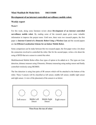
  • 1. Mimi Madihah Bt Mohd Idris 1061110400 Development of an internet controlled surveillance mobile robot. Weekly report Week 5 For this week, doing some literature review about Development of an internet controlled surveillance mobile robot. By reading some of the research paper gives some valuable information to improve the project more. Until now, there were two research papers, the first paper is Internet Control of a Domestic Robot Using a Wireless Lan and the second papers are An Efficient Localization Scheme for an Indoor Mobile Robot. Some comparison can be make between this two research paper, the first paper write a lot about the connection involved to controlled the robot. But for the second paper, writes a lot about the using of RFID that act a sensor to control the robot. Multifunctional Mobile Robot offers four types of option to be added on it. The types are Line detection, distance measure using Ultrasonic, Distance measuring using analog sensor and finally controlled wirelessly using SKXBEE. The line detection is using four pairs of IR sensors which will be attached to the bottom of the robot. These 4 sensors will be classified as left sensor, middle left sensor, middle right sensor and right sensor. A view of the placement of the sensors is as below:
  • 2. The distance between 2 sensors depends on the width. The sensor should be placed in such a way that maximum distance of two sensors is equal to the width of the line as shown in figure below. To teach the robot for line detection, user may follow these steps: 1. Adjust the robot so that the center infrared sensor is on top of white floor; make sure the wheels and castor of the robot touches the floor properly. 2. Use the screw driver to adjust the preset of center sensor until indicator LED (center) light ON. 3. Now adjust the robot to move the center sensor towards the black line where the reflection of infrared is poor. 4. At this point, make sure the indicator LED is OFF. If the LED is still on, it means user has over tune the preset. Tune it back so that the indicator is OFF. 5. Repeat step 1 - 4 for a few time and make sure the indicator LED ON and OFF correctly at the right spot. 6. Repeat step 1 - 5 to "teach" left sensor and right sensor. How the sensors function when the robot follows a black line on a white floor: This is the concept of a line following robot. We can see that when the middle sensor detects the line, the robot will move forward. This is because the line is in the center of the robot. But when
  • 3. the left sensor or the right sensor detects the black line, this means that the robot have strayed from the line. If the robot strayed to the right, the left sensor will detect the line and the brain will react by turning left to go back to the line. As for the right sensor, it reacts in the opposite way. After going through the user’s manual, and the programming code, the line detection only works well when the robot detected black line on white floor. This is because the sensor itself only for detecting black and white. To change the choices of the color is depends on the sensor color that the robot use. For this project, the robot is using white and black sensor for the line detection.
  • 4. Week 6 Discussing about the location for the spy camera so that the view is clear enough to be view from the laptop. Read some information how the Xbee works and how to use it on the Multifunctional Mobile Robot. Some step need to be done first before the both can work well together. The first step is to test the both Xbee with two laptops. After the both Xbee communicate, then one of the Xbee ready to put on the Multifunctional Mobile Robot. Some problem occurs when the Xbee on the Multifunctional Mobile Robot does not communicate with other Xbee. So some research needs to be done in order this problem can be solved immediately. Looking at the programming, it seem have some error occurs. So after contact the technical department, they found that some error in the programming and they upload the correct programming that works well with Xbee. Xbee Pro offers indoor communication range up to 100m and outdoor line of sight range up to 1500m.The both Xbee Pro works well with each other with that range by using computer. For this project, both Xbee Pro are using for controlling the Multifunctional Mobile using the keyboard, one Xbee Pro will be located at the computer and the other one will be located on Multifunctional Mobile Robot. The user may control the robot using Num pad 8 to move forward, 4 to turn left, 6 to turn right, and 2 to move backward.
  • 5. Below is the example of programming code for Xbee part: //Mode 4 : Xbee // Description : Control the robot using UART ( XBEE or an UART wireless module. //============================================================================================ ================ void wireless_xbee (void) { lcd_clr(); // clear the lcd while(1) // looping forever { lcd_goto (0); if (data[0] == 100) // check if UART start byte is met { send_string(" XBEE CONTROL "); // display string SPEEDL = 200; // set the motor speed SPEEDR = 200; while(1) { lcd_goto(20); if (RCREG == '8') // if character '8' is detected, the robot move forward { forward(); send_string("FORWARD "); } else if (RCREG == '2') // if character '2' is detected, the robot move backward {
  • 6. backward(); send_string("BACKWARD "); } else if (RCREG == '6') // if character '6' is detected, the robot turn right { right(); send_string("TURN RIGHT "); } else if (RCREG == '4') // if character '4' is detected, the robot turn left { left(); send_string("TURN LEFT "); } else if (RCREG == '5') // if character '5' is detected, then stop the robot { stop(); send_string("INVALID COMMAND "); } else // else then stop the robot { stop(); send_string("INVALID COMMAND "); } } } else send_string("COMMAND"); }
  • 7. Week 7 For this week, the Multifunctional Mobile Robot experiments have been done. The experiment was done at the MMU building such as hostel and FCM. The robot was test under certain level especially the range of the robot. This is because the robot will be communicating wirelessly using Xbee Pro that can be operating at certain range. At the hostel area, the robot was able to operate at three storey building under the keyboard controlled. For the spy camera, from the description of the spy camera says that the range only up to 100m.The experiment done at hostel building, the spy camera was able to view the video up to three storey building. The results give a brief view how well the robot will work.