1. Technical Specifications Troubleshooting
Detector
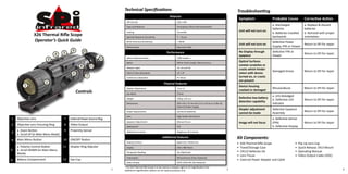
Symptom Probable Cause Corrective Action
FPA Format 320 x 240
a. Discharged a. Replace & discard
Type and Material Amorphous Silicon Microbolometer
batteries batteries
Cooling Uncooled Unit will not turn on
b. Batteries installed b. Reinstall with proper
X26 Thermal Rifle Scope Spectral Response Sensitivity 7 – 14 μm backwards orientation.
Operator’s Quick Guide NETD (Thermal Sensitivity) < 50mK Defective Power
Unit will not turn on Return to SPI for repair
Refresh Rate Real-time 30Hz Supply, FPA or Viewer
9 10 No Display through Defective FPA or
4 5 Performance Return to SPI for repair
eyepiece Viewer
3 12 Detect Stationary Man 1000 meters +
Optics 50mm Focal Length, Manual Focus
Optical Surfaces
8 11 contain scratches or
Weapon Sight 1X, 2X and 4X
cracks which hinder
Damaged lenses Return to SPI for repair
6 Field of View (Standard) 12° x 9° vision with device
7 Continuous Operation 4+ Hours turned on, or cracks
are present
2 Physical Features
1 Device housing
Diopter Adjustment -6 to +2 Misuse/abuse Return to SPI for repair
cracked or damaged
Controls Eye Relief 27mm
a. LED dislodged
Weight 700 gr. (25 oz.) Defective low-battery
b. Defective LED Return to SPI for repair
detection capability
Dimensions 205 x 65 x 72 mm (8 x 2.6 x 2.8 in) or 9-28v DC indicator
External Power Supply
Diopter adjustment Defective Eyepiece
Power Requirement (4) CR123 Batteries Return to SPI for repair
cannot be made Assembly
Lens High Grade Germanium
1 Objective Lens 7 External Power Source Plug a. Defective Sensor
Eyepiece Adjustment Manual Focus Image will not focus (FPA) Return to SPI for repair
2 Objective Lens Focusing Ring 8 Video Output
Waterproof: YES b. Defective Display
a. Zoom Button 9 Proximity Sensor
3 b. Scroll UP (in Main Menu Mode)
Additional Controls Brightness & Contrast
4 Main Menu Button 10 ON/OFF Button
Additional Features Kit Components:
Polarity Control Black Hot / White Hot • X26 Thermal Rifle Scope • Flip Up Lens Cap
a. Polarity Control Button 11 Diopter Ring Adjuster Display 640 x 480 Pixels • Travel/Storage Case • Quick-Release 1913 Mount
5 b. Scroll DOWN (in Main Menu • CR123 Batteries (4) • Operating Manual
Temperate Reading Yes (Optional)
Mode)
• Lens Tissue • Video Output Cable (VOC)
Colorization Monochrome (Color Optional)
6 Battery Compartment 12 Eye Cup • External Power Adapter and Cable
Video Output NTSC (STD) PAL (On Request)
*The X26 Thermal Rifle Scope is to be used as a weapon sight at 1X magnification only.
1 Additional magnification options are for optical purposes only. 2 3
2. Basic Controls (Seen from Eyepiece End) Use and Operation Quick Reference Battery Operation
The following instructions are intended to quickly familiarize the user with the Internal power is supplied by four 3V lithium CR123A batteries, DL123A or
X26 controls. Follow these steps to get the feel of how to navigate through the equivalent. Open the Battery Compartment by turning the battery compartment
Device Menu, make adjustments, and how to use the buttons. For complete handle counterclockwise until it stops. Insert four CR123 Batteries, position (+)
ZOOM details on every Menu Item, please consult the Operator’s Manual. down. When re-inserted, turn the knob clockwise until it stops.
BASIC Mode
MODE Menu 1. Single click n button to access Main Menu. Low Battery Indicator - Visible in the lower left hand corner of the display
ZOOM + MENU screen. When the low battery indicator appears, the unit has approximately 15
2. Navigate through Main Menu by single clicking the or buttons. minutes of remaining battery power.
MENU Enter
POLARITY
POLARITY -
3. Single click n button to access the Image Submenu.
4. Making Adjustments:
Main Menu Symbols & Functions
4
• Navigate through Submenu by single Dioptic Ring Adjuster
Symbol Name Function clicking the or buttons. Diopter adjustment allows for proper optical
• To Select an item to be adjusted, correction for each individual’s eyesight.
Image Adjust Brightness, Contrast & Backlight Settings This adjustment is easily made, and is
single-click the n button.
5 • Use the or buttons to make
recommended prior to use. Select an object
to focus on and adjust the diopter ring by
Reticle Select Type & Position of Reticle. turning either clockwise or counter-clockwise Dioptic Ring Adjuster
adjustments. until the object is the clearest.
• To save a change, press the button.
OSD Settings Select Color of Overlay Graphics 5 Storage & Maintenance of Device
The device requires careful handling. To avoid damage to optical elements
P
Profile Profile Settings of the device, use protective covers (caps). Remove moisture and dust from
5. To make further adjustments within this Submenu, continue the instrument with a soft cloth or soft bristle brush. Opticle elements should
be using a microfiber lens cleaning cloth. The device should be stored without
Proximity Adjust Eye Sensor Proximity navigating using the or buttons. batteries in a dry room.
6. To EXIT the Submenu and return to the Main Menu, press
EXIT Menu Exit
the button.
USB Mode USB to PC
7. To EXIT the Main Menu and return to the Main Viewing Screen, 6620 S. Tenaya Way, Suite #100, Las Vegas, NV 89113, USA
press and hold the button. Phone: 1.702.369.3966 • Fax: 702.369.3977
www.x20.org • sales@x20.org
4 5 6