Adjustable Differential type Vacuum Switch MA series
•
0 j'aime•142 vues

Adjustable Range : 760 to 100 mm Hg Vacuum Enclosure : IP 54, IP 65, IP 66 & Flameproof Pressure Housing : Aluminium, Brass or, SS 316 Diaphragm : Neoprene, Teflon or, SS 316 Differential : Adjustable from 100 to 500 mm Hg Max. Working Pressure : 12 bar Switch type : 1 no. SPDT snap action micro switch Switch rating : 5A, 250V AC Or, 0.2A, 250 V DC Cable Gland : 3/8” Cable Entry Calibration Scale : Optional Pressure Port : 1/4” BSP (F) Repeatability : 1% FSR

Recommandé
Recommandé
Contenu connexe
Tendances
Tendances (18)
En vedette
En vedette (20)
Similaire à Adjustable Differential type Vacuum Switch MA series
Similaire à Adjustable Differential type Vacuum Switch MA series (20)
Plus de NK Instruments Pvt. Ltd.
Plus de NK Instruments Pvt. Ltd. (20)
Dernier
Dernier (20)
Adjustable Differential type Vacuum Switch MA series
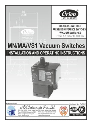
- 1. NK Instruments Pvt. Ltd.B-501/504, 5th floor, Raunak Arcade, Near THC Hospital, Gokhale Road, Naupada, Thane(W) 400602. Maharashtra INDIA Telefax Nos.: 91-22-25301330 / 31 / 32 E-Mail: sales@nkinstruments.com Web: http://www.nkinstruments.com Skype: nitinkelkarskype Gtalk: nkinstruments2006 Authorised Dealer ounting 5 dia. 1.36 0.98 25 ø5 Hole (To be always open to Atmosphere) 2.17 55 3/8" Cable Entry Terminal Strip Set Screw Cover 123 4.84 VACUUM SWITCH 85 3.35 INSTALLATION AND OPERATING INSTRUCTIONS MN/MA/VS1 Vacuum Switches Certificate No.: FM72815 PRESSURE SWITCHES PRESSURE DIFFERENCE SWITCHES VACUUM SWITCHES From 1.5 mbar to 600 bar
- 2. INSTALLATION AND OPERATING INSTRUCTIONS FOR MN/MA/VS1 VACUUM SWITCHES Construction The vacuum switch is housed in a die-cast aluminium enclosure which confirms to IP54 protection factor. Rubber gaskets can be provided optionally to provide an IP65 enclosure. For calibrated models a scale, visible through a window, is provided. The pressure capsule, comprises a housing (aluminum), a disc (either Aluminium or Brass), nylon reinforced rubber diaphragm, junction plate (Aluminum), Teflon diaphragm, Teflon 'O' ring and a plunger (SS316). The electrical changeover is through a snap action microswitch. The electrical wiring terminates at a terminal strip having screwed ends. A 3/8" cable gland has been provided for cable entry. Principle of Operation The negative pressure in the pressure capsule is converted into force by means of a reinforced rubber diaphragm and plunger which is balanced by a compression spring. When the force generated by the vacuum in the pressure capsule exceeds/falls beyond the balancing spring force, an electrical element is actuated. Mounting Please refer Fig. 1.1 The vacuum switches can be mounted in any direction. a) Vacuum switches can be mounted directly in case the mounting is rigid. b) For panel mounting, use M5 bolts of appropriate length through the mounting holes. If the equipment is subject to vibration, please use rubber washers / pads between the panel and the switch. Electrical Connections Vacuum switches will generally have only one SPDT microswitch. Wiring Please refer Fig. 1.3 a) Remove the right hand side (RHS) cover. b) Pass the cable through the cable gland and connect the wiring as per the wiring diagram. The colour code is as per the details given below. Terminal 1 (common): Red Terminal 2 (Normally closed): Black Terminal 3 (Normally open): Yellow Fig. 1.2 Z 2 3 1 Fig. 1.1 2 INSTALLATION DRAWING APPROX. DIMENSIONS IN mm inches Set Screw Cover 2 nos. Mounting Holes, Ø5 Hole (to be Always Open to Atmosphere) 34.5 25 0.98 123 4.84 85 3.35 55 2.17 Terminal Strip 3/8” Cable Entry Vacuum Port 1/4” Differential Screw VACUUM SWITCH (for MA series only)1.36 BSP Female 5.5 dia.
- 3. Fig 1.3 Mounting Holes Cable Gland RHS Cover Terminal Strip Main Body Set Screw Cover Set Screw mmHg 3 Set Point Adjustment For MN/VS1 Models: Please refer Fig. 1.3 1) Remove the setscrew cover . 2) i) For MN/VS1 uncalibrated Models 2.1 Turn the setscrew to the extreme negative end. ii) For MN calibrated Models 2.1 Adjust the desired setpoint on the scale. 3) Apply the desired cutin (lower) / cutout (higher) vacuum to the vacuum switch. 4) i) For MN/VS1 uncalibrated Models 4.1 Increase the vacuum setting by turning the setscrew till contacts changeover. ii) For MN calibrated Models 4.1 Proceed to Step 5 5) Some minor adjustment will be required to achieve the exact cutin (lower) / cutout (higher) point, which can be checked with the help of a proper vacuum measurement device. 6) Replace the setscrew cover. Tip. : The vacuum switches are factory set at half the setpoint range (unless otherwise specified in a Purchase Order). Step 2 can be omitted if the desired set point is more than the factory setting. SET POINT ADJUSTMENT FOR MA MODEL 1) Decide the cut-in (lower) vacuum V1 & the cut-out (upper) vacuum V2. The differential will be (V2 - V1). 2) Remove the set screw cover. 3) a) For MA uncalibrated models i) Turn the setscrew to the extreme positive end. ii) Turn the differential screw to the extreme negative end. iii) Apply the desired cutin (lower) vacuum to the vacuum switch. iv) Increase the vacuum setting by turning the setscrew till contacts changeover. b) For MA calibrated models i) set the cut-in point on the main-scale with the help of the set-screw. 4) Turn the differential screw to the extreme positive end. 5) Apply the desired cutout (higher) vacuum to the vacuum switch. 6) Decrease the differential vacuum setting by turning the differential screw till contacts changeover. 7) Some minor adjustment will be required to achieve the exact cutin (lower) / cutout (higher) point, which can be checked with the help of proper vacuum measurement device. 8) Replace the setscrew cover.
- 4. NK Instruments Pvt. Ltd. B-501/504, 5th floor, Raunak Arcade, Near THC Hospital, Gokhale Road, Naupada, Thane(W) 400602. Maharashtra INDIA Telefax Nos.: 91-22-25301330 / 31 / 32 E-Mail: sales@nkinstruments.com Web: http://www.nkinstruments.com Skype: nitinkelkarskype Gtalk: nkinstruments2006 Authorised Dealer Fig. 1.4 Calibrated Vacuum Gauge System Vacuum 'T' Connection VACUUM Switch VACUUM SWITCH Trouble Shooting Tips Generally no problems are observed if the vacuum switch selection, wiring and the setpoint is proper. For a vacuum switch selection procedure, please consult our sales office. For properly selected vacuum switches, if following symptoms are observed, the likely causes and remedies are as stated below. Symptom 1: Switch does not operate. 1) Wiring may not be correct. Check electrical connections to the vacuum switch, if they are as per the wiring diagram. 2) Vacuum does not reach the vacuum port. a) Check if the entry to the pressure capsule is not blocked by frozen process or scales or impurities in the process. i) If this is the case, try freeing the blocked path by a blunt tool in case of scales and impurities. If the cause is none of the above mentioned probabilities , proceed as per the following steps. b) Check the system vacuum & set point of vacuum switch. i) For use of vacuum switch for falling setpoints, system vacuum has to be greater than the cutout point. ii) For use of vacuum switch for rising setpoints, the system vacuum may not be reaching / exceeding the cutout point. c) For MA model turn the differential screw to the extreme negative end. d) Use 'T' connection & connect calibrated vacuum gauge to the 'T' connection as shown in the figure. e) Adjust the setpoints such that the system vacuum is greater than the cut-out point of the vacuum switch. If the switch still does not operate, remove the vacuum switch physically from the system. There should be continuity between terminals 1&2. If no continuity is observed, the vacuum switch should be returned to the factory. Symptom 2: Short Wiring Isolate the switch electrically. Check the continuity between terminals and the screws fitted to the body. If no continuity is observed between any of the terminals and the screws fitted to the body, check the short connection elsewhere in the circuit. If continuity is observed, the wires of the vacuum switch have internally touched the body, and the switch should be returned to the factory. Symptom 3: Leakage In case leakage is observed, the vacuum switch has to be returned to the factory without opening the pressure capsule. Check for the following likely causes and use a new switch taking proper precautions. a) System pressure is greater than specified maximum working pressure. b) Incompatible wetted parts: The working medium may not be compatible with wetted parts, which damages the sealing of the process from working parts. c) Excessive process temperature: Process temperature may exceed maximum allowable temperature, which in turn damages the diaphragms. Use an impulse tubing of proper length for cooling the process temperature. There may be a vacuum drop depending on length of the impulse tube used. Adjust the setpoint of the pressure switch accordingly. Symptom 4: Chattering 1) Chattering is observed where the system vacuum is close to the cutin / cutout point and the surge vacuum exceeds the on-o ffdifferential. Use a vacuum switch with an adjustable differential.