Flameproof High Range Pressure Switches FE Series
•
0 likes•192 views

Flameproof Pressure Switches are designed as per IS2148 for Gas Gr. IIC Flameproof - CE Certification and approved by a leading European Lab – “BASEEFA” for ATEX & ICEEX certificates Various Ranges : from 0 to 150 mm Wc upto 0 to 400 Bar Differential (Dead Band) : Fixed (Within 10% of set value) Or, Adjustable Sensing Element : Diaphragm (PTFE, Neoprene or, SS 316) or Piston Enclosure : Flameproof to group IIC

Recommended
Recommended
More Related Content
What's hot
What's hot (20)
Similar to Flameproof High Range Pressure Switches FE Series
Similar to Flameproof High Range Pressure Switches FE Series (20)
More from NK Instruments Pvt. Ltd.
More from NK Instruments Pvt. Ltd. (20)
Recently uploaded
Recently uploaded (20)
Flameproof High Range Pressure Switches FE Series
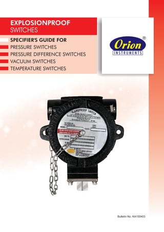
- 1. SPECIFIER'S GUIDE FOR PRESSURE SWITCHES PRESSURE DIFFERENCE SWITCHES VACUUM SWITCHES TEMPERATURE SWITCHES EXPLOSIONPROOF SWITCHES Bulletin No. KA150403
- 2. Explosionproof switches : These switches have been designed for use in hazardous areas and for severe applications in the Oil and Gas sectors like oil and gas pipelines, petrochemical plants, refineries and generally in atmospheres which are potentially explosive. All switches are designed for gas group IIC, the most severe of the explosive gases, and hence can be used in lower severity atmospheres, typically in IIA and IIB. With grey cast iron enclosures, these can also be used in mines. SS enclosures can also be offered for highly corrosive atmospheres. Switches can be configured with a lot of options like electrical elements and sensing element configurations to suit the intended working media. These switches have KLPLapproval. Brief Classification APPLICATIONS ! Oil & Gas ! Petrochemical ! Refineries ! Mines ! Bulk Drug & Pharma ! Chemical Industries ! Compact, rugged Design ! Enclosure protection : IP66 Standard ! Reliable, accurate micro switches used ! Customised Micro switch arrangement can be provided, on request ! Easy, safe wiring connections ! High/low pressure options available ! Accuracy* : +/- 1% FSR / +/- 2 % FSR ! Warranty 2 Years FEATURES *Accuracy changes with switch configuration ! ! ! ! ! ! IS/IEC 60079-0: 2007, IS/IEC 60079-1:2007, IS/IEC 60079-31:2006 and IS/IEC 60529:2001. ! Storage Temp. : Atmospheric temperature Operating ambient Temp. : 0 to 60 degree C o Media Temp.:- for non-metallic diaphragms 80 C max., higher with metal diaphragms Set point repeatability : +/- 1% over full range Enclosure details : Al grade LM6 / Grey Cast Iron / Stainless Steel Casing & Cover Enclosure Specifications : Protection : IP66 Standard Complies to : Grey CI enclosure for mines (Group I applications) Switch output 1 SPDT (2 SPDT on request). ! ! ! 6 PRODUCT SPECIFICATIONS: II 2 GD Ex d IIC Gb Ex tb IIIC Db T85°C (-20°C < Ta < +60°C) IP66
- 3. 1 Bulletin No. KA150403 Information and data in this catalog are formatted to provide a convenient guide to assist instrument engineers, plant engineers and end users in selecting pressure switches for their unique applications. Steps 1 through 6 are required. Step 7 is optional. Orders must have complete Model Numbers, i.e. each component must have a designator. Step 1: Select Cable Entry (page 2). Step 2: Select Switch Type (page 3). Step 3: Select Range Code of pressure switch (page 4). Step 4: Select Microswitch Type, electrical Switching Element for electrical service (page 6). Step 5: Select Pressure Port for process compatibility and connection (page 7). Step 6: Select Diaphragm for process compatibility and containment (page 9). Step 7: Select Accessories required for service (page 13). How to Order N FE 1 D1 L03 A1 S1 0 DiaphragmSwitch Type Microswitch Type Explosion Proof Accessories & Non-Standard Combinations Range Code Pressure Port Conduit/ Cable Entry
- 4. 1 = Al. Head ½” NPT threads 2 = Al. Head ¾”” NPT threads 3 = Al. Head M20*1.5 threads 4 = Grey CI Head ½” NPT threads 5 = Grey CI Head ¾” NPT threads 2 Bulletin No. KA150403 Switch Construction a) Explosionproof Head (Casing + Cover) b) Electrical Element (s) c) Pressure Capsule Casing Cable Entry 6 = Grey CI Head M20*1.5 threads 7 = SS Head ½” NPT threads 8 = SS Head ¾” NPT threads 9 = SS Head M20*1.5 NPT threads Conduit/ Cable Entry 1N FE D1 L03 A1 S1 0 Cover
- 5. 3 Bulletin No. KA150403 Switch Type D1N FE 1 L03 A1 S1 0 High rrange p essure Capsule 1 1 1 1 1 1 1 1 P A D V C T Pressure Switches 1) High Range 2) Low Range ANSI Flanged Pressure Difference Switches 1) High Range 2) Low Range Vacuum Switch Compound Switch Temperature Switch Without Scale Without Scale Without Scale Without Scale Without Scale Without Scale Without Scale Without Scale Switch Type Switch Designator Pressure Capsule Details High Proof High Range Flanged Range Low Range Pressure Difference Compound RangeVacuum High Range Pressure Difference High Range DP High Proof Range Pressure Difference High High Range Bellows Low Range Hydraulic Range Low ÄP High Proof Pressure Difference Switches
- 6. Range Code N FE 1 D1 A1 S1 0L03 4 Bulletin No. KA150403 P = Pressure Switch P1 = Bellows P2 = Hydraulic 0.067 - 0.213 (0.97 - 3.09) 0.1 - 0.5 (1.45 - 7.25) 0.1 - 1.0 (1.45 - 14.50) 0.1 - 1.5 (1.45 - 21.76) 0.2 - 2.6 (2.90 - 37.71) 0.2 - 3.6 (2.90 - 52.21) 0.5 - 7.0 (7.25 - 101.50) 0.5 - 10.0 (7.25 - 145.037) 1.0 - 15.0 (14.5 - 217.56) 5.0 - 25.0 (72.52 - 362.6) 0.1 - 1.0 (1.45 - 14.50) 0.1 - 1.5 (1.45 - 21.76) 0.2 - 2.6 (2.90 - 37.71) 0.2 - 3.6 (2.90 - 52.21) 0.5 - 7.0 (7.25 - 101.50) 0.5 - 10.0 (7.14 - 142.86) 1.0 - 15.0 (14.29 - 214.29) 5.0 - 25.0 (71.43 - 357.14) 5 - 40 (72.52 - 580.15) 10 - 100 (145.037 - 1450.37) 0.5 - 10 (7.25 - 145.04) 2 - 20 (29.00 - 290.08) 7 - 200 (101.53 - 2900.76) 40 - 400 (580.15 - 5801.52) Range bar (psi) 5 (72.52) 5 (72.52) 12 (174.05) 12 (174.05) 12 (174.05) 12 (174.05) 12 (174.05) 25 (362.6) 25 (362.6) 35 (507.63) 70 (1015.26) 200 (2900.76) 70 (1015.26) 200 (2900.76) 70 (1015.26) 200 (2900.76) 70 (1015.26) 200 (2900.76) 70 (1015.26) 70 (1015.26) 70 (1015.26) 70 (1015.26) As per the class of flange 100 (1450.37) 200 (2900.76) 200 (2900.75) 150 (2175.00) 200 (2900.76) 400 (5801.52) 500 (7251.90) Maximum Working Pressure bar (psi) 0.02 (0.29) 0.08 (1.16) 0.10 (1.45) 0.12 (1.74) 0.15 (2.17) 0.20 (2.90) 0.20 (2.90) 0.40 (5.80) 0.50 (7.25) 1.0 (14.5) 0.20 (2.9) 0.24 (3.48) 0.20 (2.9) 0.40 (5.80) 0.30 (4.35) 0.40 (5.80) 0.40 (5.80) 0.60 (8.70) 0.50 (7.25) 0.80 (11.6) 1.50 (23.2) 1.50 (23.2) 5 (72.52) 5 (72.52) 5 (72.52) 12 (174.05) 0.5 (7.25) 2 (29.00) 24 (348.09) 70 (1015.27) Differential* bar (psi) Approximate Maximum for "A1" microswitch Range Code LP LP5 H01 H02 H03 H04 H07 H10 H15 H30 P01 P02 P03 P04 P07 P10 P15 P30 H4T H1H H1T H2T H2H H4H P P P, A, D P, A, D P, A, D P, A, D P, A P, A P, A P, A P D P D P D P D P P P P A P1 P2 P, A P P P, A P Switch Type A = ANSI Flanged Switch D = Pressure Difference Switch V = Vacuum Switch C = Compound Switch T = Temperature Switch
- 7. 50 - 700 (725.19 - 10152.70) 100 - 1000 (1450.37 - 14503.77) 1.0 - 15.0 (14.50 - 217.56) 5.0 - 25.0 (72.52 - 362.59) -1 to 1.0 (-14.50 - 14.50) -1 to 2.6 (-14.50 - 37.71) -1 to 3.6 (-14.50 - 52.21) -150 to 150 (-5.905 - 5.905) -250 to 250 (-9.842 - 9.842) 0.1 - 1.0 (1.45 - 14.50) 0.1 - 1.5 (1.45 - 21.76) 0.2 - 2.6 (2.90 - 37.71) 0.2 - 3.6 (2.90 - 52.21) 0.5 - 7.0 (7.25 - 101.50) 0.5 - 10.0 (7.25 - 145.037) Range bar (psi) 1000 (14503.77) 1200 (17404.53) 70 (1015.26) 70 (1015.26) 12 (174.05) 12 (174.05) 12 (174.05) 2 (29.00) 2 (29.00) 70 (1015.26) 70 (1015.26) 70 (1015.26) 70 (1015.26) 70 (1015.26) 70 (1015.26) Maximum Working Pressure bar (psi) 50 (725.19) 70 (1015.26) 0.50 (7.25) 0.50 (7.25) 0.2 (2.90) 0.6 (8.702) 0.8 (11.603) 40 (1.605) 60 (2.410) 0.10 (1.45) 0.12 (1.74) 0.17 (2.46) 0.10 (1.45) 0.20 (2.9) 0.20 (2.9) Differential* bar (psi) Approximate Maximum for "A1" microswitch H7H H1K D15 D30 C01 C03 C04 CL2 CL3 D01 D02 D03 D04 D07 D10 P P D D C C C C C D D D D D D Switch Type Range Code 1.5 - 15 (0.602 - 6.021) 5 - 25 (2.007 - 10.037) 10 - 50 (4.015 - 20.073) 10 - 100 (4.015 - 40.150) 10 - 150 (4.015 - 60.22) 20 - 250 (8.029 - 100.36) 50 - 350 (20.073 - 140.52) 5 - 25 (2.007 - 10.037) 10 - 50 (4.015 - 20.073) 10 - 100 (4.015 - 40.150) 10 - 150 (4.015 - 60.22) 20 - 250 (8.029 - 100.366) 50 - 350 (20.073 - 140.52) Range in mbar ("wc) 2 (29.00) 2 (29.00) 2 (29.00) 2 (29.00) 2 (29.00) 2 (29.00) 2 (29.00) 100 (1450.38) 100 (1450.38) 100 (1450.38) 100 (1450.38) 100 (1450.38) 110 (1595.00) Maximum Working Pressure bar (psi) 3 (1.204) 5 (2.007) 5 (2.007) 5 (2.007) 5 (2.007) 10 (4.015) 25 (10.04) 5 (2.007) 5 (2.007) 10 (4.015) 10 (4.015) 15 (6.022) 35 (14.05) Differential* mbar ("wc) Approximate Maximum for "A1" microswitch Range Code L02 L03 L05 L10 L15 L25 L35 M03 M05 M10 M15 M25 M35 P, D P, D P, D P, D P, D P, D P, D D D D D D D Switch Type † 760 - 100 (29.92 - 3.94) Range mmHg ("Hg) 12 (174.05) Maximum Working Pressure bar (psi) 10 (0.39) Differential* mmHg ("Hg) Approximate Maximum for "A1" microswitch Range Code V00 V Switch Type 150 (302) 200 (392) 300 (572) Maximum Working o o Temperature C ( F) 15 (59) 20 (68) 30 (86) o o Differential* C ( F) Approximate Maximum for "A1" microswitch 25 - 90 (77 - 194) 70 - 150 (158 - 302) 120 - 215 (248 - 419) o Range C o ( F) Range Code T1H T2H T3H T T T Switch Type 5 Bulletin No. KA150403
- 8. Microswitch Type N FE 1 D1 L03 S1 0A1 6 Bulletin No. KA150403 Following table lists standard microswitches and their electrical ratings that can be supplied with most FE models. Please get in touch with sales office for feasibility of options on each model. Please write to us on electrical rating options you need, but are not mentioned below. MICROSWITCH OPTIONS VDC NA 28 NA 125/250 125/250 24 28 28 NA 125/250 28 30 NA NA NA 28 28 NA 28 Inductive (A) NA 2 NA NA NA NA 3 3 NA NA 2 0.5 NA NA NA 3 3 NA 4 General Description General Purpose Microswitch Hermetically Sealed for Corrosive Environments Gold Plated Contacts for Low Voltage Applications DPDT Configuration For High DC Ratings Elements with Adjustable Deadband 2SPDT Switching Elements General Purpose Microswitch General Purpose Microswitch General Purpose AC/DC Ratings 2SPDT Hermetically Sealed Microswitches 2SPDT Gold Plated Contacts for Low Voltage Applications Manual Reset Microswitch 2SPDT Switching Elements 2SPDT Adjustable 1 SPDT Adjustable Differential 2 SPDT Adjustable Differential Hermetically Sealed Gold Plated Hermetically Sealed Silver Plated Inductive (A) NA 2 NA NA NA NA NA NA NA NA 2 NA NA NA NA NA NA NA NA Resistive (A) 15 4 1 10 NA 15 5 5 15 15 2 1 15 15 5 5 5 1 7 AC Rating Current VAC 125/250/480 115 125/250 125/250 NA 115/250 250 125/250 125/250 125/250/480 115 125/250 125/250/480 125/250 125/250 250 250 125 250 Voltage Resistive (A) NA 4 NA 0.3/0.15 10/3 1 5 5 NA 0.25/0.5 4 1 NA NA NA 5 5 NA 7 Code A1 A2 A3 A4 A5 A6 A7 A8 A9 B1 B2 B3 B4 B7 B9 C6 C7 D6 D7 Voltage DC Rating Current
- 9. FE High Pressure Range FE High Proof High Range FE Low Pressure Range FE Hydraulic Range FE High Range Pressure Difference FE High Proof High Range PD FE High Range DP FE Low Range Pressure Difference FE Low ÄP High Proof FE Vacuum Range FE Compound Range S3 S4 S5 H1 H2 H3 H4 H5 Material Stainless Steel (SS) Hastelloy C Pressure Port Code Size 1” BSP(M) ½” NPT(F) ½” NPT(M) ¼” BSP(F) ¼” NPT(F) 1” BSP(M) ½” NPT(F) ½” NPT(M) FE High Pressure Range FE High Proof High Range FE Low Pressure Range FE Hydraulic Range FE High Range Pressure Difference FE High Proof High Range Pressure Difference FE High Range DP FE Low Range Pressure Difference FE Low ÄP High Proof FE Vacuum Range FE Compound Range N1 N2 N3 N4 N5 Material Monel SS316 Pressure Port Code Size ¼” BSP(F) ¼” NPT(F) 1” BSP(M) ½” NPT(F) ½” NPT(M) S1 S2 ¼” BSP(F) ¼” NPT(F) PRESSURE PORT OPTIONS 7 Bulletin No. KA150403 B1 B2 SS316 FE High Range Bellow Material Pressure Port Code Size ¼” BSP(F) ¼” NPT(F) B1 B2 SS316 FE Temperature Material Temperature Bulb Code Size 3/8” BSP(M) 3/8” NPT(M) B3 ½” NPT(M) Pressure Port N FE 1 D1 L03 A1 0S1
- 10. Class 150# 1/2" 3/4" 1" 1 1/4" 1 1/2" 2" 300# 1/2" 3/4" 1" 1 1/4" 1 1/2" 2" 400# 1/2" 3/4" 1" 1 1/4" 1 1/2" 2" 600# 1/2" 3/4" 1" 1 1/4" 1 1/2" 2" 900# 1/2" 3/4" 1" 1 1/4" 1 1/2" 2" 1500# 1/2" 3/4" 1" 1 1/4" 1 1/2" 2" 2500# 1/2" 3/4" 1" 1 1/4" 1 1/2" 2" Flanges conform to ANSI B16.5; maximum pressure is limited by flange rating Stainless Steel 316 L Raised AA AB AC AD AE AF Raised AG AH AI AJ AK AL Raised AM AN AO AP AQ AR Raised AS AT AU AV AW AX Raised AY AZ BA BB BC BD Raised BE BF BG BH BI BJ Raised BK BL BM BN BO BP Flat BQ BR BS BT BU BV Flat BW BX BY BZ CA CB Flat CC CD CE CF CG CH Flat CI CJ CK CL CM CN Flat CO CP CQ CR CS CT Flat CU CV CW CX CY CZ Flat DA DB DC DD DE DF Hastelloy C276 Raised DG DH DI DJ DK DL Raised DM DN DO DP DQ DR Raised DS DT DU DV DW DX Raised DY DZ EA EB EC ED Raised EE EF EG EH EI EJ Raised EK EL EM EN EO EP Raised EQ ER ES ET EU EV Flat EW EX EY EZ FA FB Flat FC FD FE FF FG FH Flat FI FJ FK FL FM FN Flat FO FP FQ FR FS FT Flat FU FV FW FX FY FZ Flat GA GB GC GD GE GF Flat GG GH GI GJ GK GL Alloy 400 Monel Raised GM GN GO GP GQ GR Raised GS GT GU GV GW GX Raised GY GZ HA HB HC HD Raised HE HF HG HH HI HJ Raised HK HL HM HN HO HP Raised HQ HR HS HT HU HV Raised HW HX HY HZ IA IB Flat IC ID IE IF IG IH Flat II IJ IK IL IM IN Flat IO IP IQ IR IS IT Flat IU IV IW IX IY IZ Flat JA JB JC JD JE JF Flat JG JH JI JJ JK JL Flat JM JN JO JP JQ JR Titanium Raised JS JT JU JV JW JX Raised JY JZ KA KB KC KD Raised KE KF KG KH KI KJ Raised KK KL KM KN KO KP Raised KQ KR KS KT KU KV Raised KW KX KY KZ LA LB Raised LC LD LE LF LG LH Flat LI LJ LK LL LM LN Flat LO LP LQ LR LS LT Flat LU LV LW LX LY LZ Flat MA MB MC MD ME MF Flat MG MH MI MJ MK ML Flat MM MN MO MP MQ MR Flat MS MT MU MV MW MX Tantalum Raised MY MZ NA NB NC ND Raised NE NF NG NH NI NJ Raised NK NL NM NN NO NP Raised NQ NR NS NT NU NV Raised NW NX NY NZ OA OB Raised OC OD OE OF OG OH Raised OI OJ OK OL OM ON Flat OO OP OQ OR OS OT Flat OU OV OW OX OY OZ Flat PA PB PC PD PE PF Flat PG PH PI PJ PK PL Flat PM PN PO PP PQ PR Flat PS PT PU PV PW PX Flat PY PZ QA QB QC QD FLANGE CODE TABLE H01 to H04 H07 H10 H15 H30 H2T to H2H 1" NB NA Yes Yes Yes Yes Yes 2" NB Yes Yes Yes Yes Yes Yes RANGE AVAILABILITY AS PER BORE SIZES 8 Bulletin No. KA150403
- 11. Capilary (for Temperature Switch) 0N FE 1 D1 L03 A1 S1 High Pressure Range High Proof High Range High Range Bellows Low Pressure Range Hydraulic Range Flanged Pressure Range High Range Pressure Difference High Proof High Range Pressure Difference High Range DP Low Range Pressure Difference Low DP High proof Pressure Difference Vacuum Compound Switches 0 1 2 3 4 65 7 Diaphragm (for Pressure Switches) 0 =Neoprene 1 =Teflon 2 =SS316L 3 =Hastelloy C 4 =Monel 5 =Titanium 6 =Tantalum 7 = Inconel Diaphragm (for Pressure Switches) / Capilary (for Temperature Switch) 2 =SS316 / 2.0 mtr. P P A D D D D D V C P P P S/W Type Diaphragm Temperature Switch Switch 2 T S/W Type Capilary 9 Bulletin No. KA150403
- 12. 10 Bulletin No. KA150403 RANGES INSTALLATION DRAWING HIGH PRESSURE APPROX. DIMENSIONS IN mm inches APPROX. DIMENSIONS IN mm inches APPROX. DIMENSIONS IN mm inches APPROX. DIMENSIONS IN mm inches Pressure Port 2 nos Ø7, Mounting Holes (4.33) (4.96) 110.0 126.0 1/4" BSP(F) 1/2" NPT(F) (Options Avail.) Cable Entry (6.22) 158 A/F 19 (A/F 0.74) HIGH RANGE HIGH PROOF SWITCHES INSTALLATION DRAWING Low Pressure Port 1/4" BSP(F) 145 (5.7) 196 (7.71) 136 (5.35) 26.0 (1.02) 110 (4.33) Ø7, Mounting Holes 2 nos HIGH RANGE BELLOWS SWITCHES INSTALLATION DRAWING Cable Entry 1/2" NPT(F) (Options Avail.) 166 (6.53) 145 (5.7) 126 (4.96) 110 (4.33)26 (1.02) 106 (4.17) A/F 19 Pressure Port 1/4" BSP(F) (0.74) Ø7, Mounting Holes 2nos LOW PRESSURE RANGES INSTALLATION DRAWING 145 126 Ø7, Mounting Holes 2 Nos Ø130.0 (5.11) (5.7) (4.96) 26.0 110.0 (4.33) (1.02) 1/4"BSP(F) 188 (7.40) 128 (5.03) Cable Entry 1/2" NPT(F) (Option avail.) Pressure Port (1.02) 26 (2.0) 50.8 (5.7) 145.0 (3.85) 98 126 (4.96) Ø72 (2.83) 22 A/F (0.86) High Pressure Port 1/4" BSP(F) 50.8 (2.0) Mounting Nut 3/4" BSP(M)
- 13. RANGES INSTALLATION DRAWING HYDRAULIC 145 (5.7) 126 (4.96) Ø7, Mounting Holes 2 nos 26 (1.02) 110 (4.33) SWITCHES INSTALLATION DRAWING FLANGED PRESSURE PRESSURE DIFFERENCE SWITCHES INSTALLATION DRAWING HIGH RANGE HIGH HIGH PRESSURE DIFFERENCE SWITCHES INSTALLATION DRAWING RANGE PROOF APPROX. DIMENSIONS IN mm inches APPROX. DIMENSIONS IN mm inches APPROX. DIMENSIONS IN mm inches APPROX. DIMENSIONS IN mm inches 11 Bulletin No. KA150403 50.8 (2.0) 177 (6.96) 117 (4.60) CABLE ENTRY 1/2" NTP(F) (Options Avail.) PRESSURE PORT 1/4" BSP(F) A/F 19 (0.74) 26 (1.02) Ø158.7 (Ø6.24) 110 (4.33) 35.1 (1.38) CABLE ENTRY 1/2" NPT(F) (Options Avail.) Ø7, Mounting Holes 145.0 (5.7)126 (4.96) 2 nos 1"NB 2500 RF ANSI FLANGE 205 (8.07) 145 (5.70) 145 (5.7) 126 (4.96) 186 (7.32) 126 (4.96) 1/4" BSP(F) Low Pressure Port 34.5 (1.35) 1/4" BSP(F) High Pressure Port Cable Entry 1/2" NPT(F) (Options Avail.) Ø7, Mounting Holes 2 nos 110 (4.33)26 (1.02) 50.8 (2.0) 126 (4.96) 145 (5.7) Ø7, Mounting Holes High Pressure Port 2 NOS 1/4" BSP(F) 136 (5.35) LOW PRESSURE PORT 196 (7.71) 1/4" BSP(F) A/F 22 (0.86) 110 (4.33)26 (1.02) Ø72 (2.83)
- 14. HIGH RANGE DP INSTALLATION DRAWING 110 (4.33)26 (1.02) 50.8 (2.0) 210 (8.26) 145 (5.7) 126 (4.96) 150 (5.90) Low Pressure PortHigh Pressure Port 2 nos Ø7, Mounting Holes PRESSURE DIFFERENCE SWITCHES INSTALLATION DRAWING LOW RANGE 26.0 110.0 Ø130.0 (4.33) (1.02) (Ø5.11) 1/2" NPT(F) (Option avail.) Cable Entry 145 126(5.7) (4.96) 1/4"BSP(F) Low Pressure Port 1/4" BSP(F) High Pressure Port128 (5.03)188 (7.40) Ø7 Mounting Holes 2 nos LOW ÄP HIGH PROOF PRESSURE DIFFERENCE SWITCHES INSTALLATION DRAWING 110 (4.33) Ø150 (Ø5.90) 26.0 (1.02) (1.77) Low Pressure Port 1/4" BSP(F) 145 Cable Entry 1/2" NPT(F) (Options Avail.) 216 (8.50) (5.7) 126 (4.96) 156 (6.14) 45 High Pressure Port 1/4" BSP(F) 145 A/F (1.02) Ø11 (0.43) Mounting Holes 4 Nos. on 132 PCD (5.2) 60/120/60 Deg. apart. VACUUM SWITCHES INSTALLATION DRAWING APPROX. DIMENSIONS IN mm inches APPROX. DIMENSIONS IN mm inches APPROX. DIMENSIONS IN mm inches 12 Bulletin No. KA150403 1/4" BSP(F) 1/4" BSP(F) 50.8 (2.0) Mounting Nut3/4" BSP(M) (2.0) 110.0 (4.33)26.0 (1.02) APPROX. DIMENSIONS IN mm inches 1/2" NTP(F) (Options Avail.) Cable Entry 2 nos Ø7, Mounting Holes Ø5 (0.20) b aHole (to e lways o t apen o tmosphere) 126 145 (5.7) (4.96) Vacuum Port 1/4" BSF(F) (1.36) 34.5 186 (7.32) (4.96) 126
- 15. 13 Bulletin No. KA150403 Following accessories can be provided with pressure switches to make it suitable for any particular application. Manifolds Pipe mounting brackets Mounting plates to suit other makes on the market Snubbers Syphons Chemical seals (or diaphragm seals) Adaptors to suit customer's process connection Switch savers Impulse tubes Tag plates (to display tag no. and identify the instrument) ACCESSORIES COMPOUND RANGE SWITCHES INSTALLATION DRAWING TEMPERATURE SWITCHES INSTALLATION DRAWING 145 (5.7) 158 (6.22) 126 (4.96) Cable Entry 1/2" NPT(F) (Options Avail.) 98 (3.85) S.S. Capillary Tube 2.0 Mtr. Long 1/2" NPT(M) Ø9.5 0.37 100 110.0 (4.33) 26 (1.02) 2 nos Ø7, Mounting Holes 3.93 (Options available) APPROX. DIMENSIONS IN mm inches APPROX. DIMENSIONS IN mm inches Pressure Port 1/4" BSP(F) 165 (6.49) 145 (5.7) 105 (4.13) 126 (4.96) 110.0 (4.33)26.0 (1.02) A/F19 2 nos Ø7, Mounting Holes (0.74) 50.8 (2.0) 13