SlideShare a Scribd company logo
1 of 12
Download to read offline
TYPES OF SUPPLY DUCT SYSTEMS
There are several basic types of supply and return
duct systems. Any one of the system types, or a com-
bination of different types, can be utilized to fit the
needs of a particular structure. The general types of
supply duct systems include:
radial system
extended plenum system
reducing plenum system
reducing trunk system
perimeter loop system.
Radial system
The radial duct system in its simplest form consists of
a central supply plenum that feeds a number of indi-
vidual branch ducts arranged in a generally radial
pattern (see Figure 1). It also can be designed and
sized so that each individual run leaving the plenum
can feed two or more supply outlets. This is fre-
quently the case because of the number of supply
outlets required to condition the structure success-
fully and the amount of space at the plenum available
for takeoffs.The radial system commonly is applied in
attics, crawl spaces, and in slab on grade installa-
tions (with the ducts embedded in the slab). It can be
used with upflow, downflow, or horizontal air handlers
and furnaces.
Extended plenum system
The extended plenum duct system (see Figure 2 on
the next page) generally consists of one or two box-
like pieces of ductwork extending from the main
plenum at the indoor unit. This extended plenum has
the same dimensions (height and width) from the
starting collar to the end of the run. Branch runs to
feed the supply outlets are tapped into the extended
plenum(s). The best results are achieved when the
maximum length of the extended plenum is not
greater than 24 ft from the air handler or furnace. If
two plenums are used, this total length can be
extended to 48 ft (see Figure 3 on the next page). If
longer distances are required based on the physical
layout of the structure, consideration should be given
to using one of the other designs discussed below
(such as the reducing plenum or the reducing trunk
duct system). There is another area of concern with
the extended plenum system—because of the higher
velocities in the plenum, it is possible that the
branches closest to the indoor blower may not feed
the desired amount of air (cfm).
1
Refrigeration Service
Engineers Society
1666 Rand Road
Des Plaines, Illinois 60016
DUCT SYSTEM DESIGN CONSIDERATIONS
Part 1
by Roger M Hensley, CMS
© 2005 by the Refrigeration Service Engineers Society, Des Plaines, IL
Supplement to the Refrigeration Service Engineers Society.
630-148
Section 11A
Figure 1. Radial duct system
2
Figure 2. Extended plenum duct system (single plenum)
Figure 3. Extended plenum duct system (double plenum)
ACCA
Never start a branch run from the end cap of an ex-
tended plenum. For best results, the starting collar of
a branch run should never be any closer than 24 in.
from the end cap. To sum up, observe the following
general rules for the extended plenum system:
Single plenums should not exceed 24 ft in length.
Double plenums should not exceed 48 ft in total
length.
Keep branch run starting collars 24 in. from the
end caps.
Never locate a takeoff in the end cap.
Reducing plenum system
The reducing plenum duct system (see Figure 4) can
be used when the physical size or layout of the struc-
ture calls for greater distances than the length con-
straints imposed on the extended plenum (24 ft). The
concept of the reducing plenum system is simple—
when the air velocity lost to the branch runs reaches
approximately 50%, the plenum size is reduced to
regain the velocity in the remaining portion of the
plenum. This reduction also improves the air flow
characteristics at the branch ducts that are closest to
the air-handling unit.The 50% rule is demonstrated in
Figure 5 on the next page. Note that at the start of the
plenum, there is an available air volume of 1,200 cfm
and an available velocity of 900 ft/min. After the third
branch run, a total of 600 cfm has been distributed to
the branches and the velocity in the plenum has been
reduced to 450 ft/min. These conditions indicate that
the proper location for the reduction in the plenum is
after the third branch. The outlet side of the reduction
is sized to restore the velocity in the plenum to
approximately 900 ft/min.
This system is relatively easy to fabricate and install.
Additional sheet metal sometimes is required to build
the system, but if done correctly it can deliver good
results. It may be necessary to balance the system
branch dampers properly.
Reducing trunk system
The reducing trunk duct system (see Figure 6 on
the next page) is very similar to the reducing plenum
3
ACCA
Figure 4. Reducing plenum duct system
system, with the exception that the trunk run is
reduced in size after each branch takeoff. These mul-
tiple reductions make it possible to maintain a con-
stant velocity (ft/min) in the trunk even though the
total air volume is reduced as each branch is sup-
plied. This type of system generally takes more sheet
metal to build and requires more labor to fabricate
and install. Another major concern is
that there are more joints to seal (to pre-
vent air leakage). The reducing trunk
system also can be applied using
lengths of round duct and manufactured
fittings. Round duct systems can signifi-
cantly reduce the cost of labor for fabri-
cation and installation, and produce very
satisfactory results if properly applied.
Another configuration that may be used
in some cases is known as the primary-
secondary trunk system (see Figure 7).
This type of system has a primary trunk
and two or more secondary trunks. The
“tee” fitting located at the end of the pri-
mary trunk in this system performs the
same function as the reduction in the
reducing trunk system. Each secondary trunk has a
cross-sectional area that is smaller than that of the
primary trunk. The secondary trunks are sized to
deliver the proper air volume to each branch at the
proper velocity. This type of system can be used very
successfully in a structure that spreads out in two or
more directions.
4
Figure 5. Reducing plenum “50% rule”
Figure 6. Reducing trunk duct system
ACCA
Perimeter loop system
The perimeter loop duct system (see
Figure 8 on the next page) is well-suited
for buildings that are constructed using
concrete slab on grade. It generally per-
forms better than the radial system in
such applications, especially in cold cli-
mates. However, the perimeter loop sys-
tem does have the disadvantage of
being a little more difficult to design and
more expensive to install. It is basically
laid out around the perimeter of the
structure next to the edge of the slab.
The entire perimeter loop is the same
size duct. The loop is fed by four or more
ducts radiating out from the central
plenum. They are usually the same size
as the loop duct. The boot boxes are
sized to deliver the proper cfm to each
room of the structure.
SUPPLY DUCT SYSTEM LOCATIONS
Decisions regarding the location of a supply air dis-
tribution system should be made based on the winter
design temperature for the structure’s geographic
location.Table 1 in ACCA’s Manual J lists design con-
ditions for locations in the U.S. and Canada. This
information should be consulted to ensure that the
proper type and location of duct system is selected
for the structure in question. The ASHRAE Funda-
mentals Handbook contains HVAC design criteria for
most countries around the world.
The general guidelines state that if the winter design
temperature for the location of the structure is above
35°F, then both perimeter floor and ceiling distribu-
tion systems will provide satisfactory results. If the
winter design temperature for the location of the
structure is below 35°F, the ceiling distribution sys-
tem is not recommended and the floor distribution
system should be considered. A modified type of ceil-
ing distribution system can be used if the registers
are moved closer to the outside walls and the primary
air is directed out of the occupied zone and toward
the window and door openings.
There are six basic locations for supply duct systems
in residential structures. Most residential structures
can accommodate one or more of these configura-
tions. One of the most important jobs of the designer
is to select the type of installation that best suits the
air distribution requirements of the structure and the
needs and desires of the customer. This must be bal-
anced with the cost of the installation and the comfort
conditions within the structure.The six basic locations
for supply duct systems are as follows:
attic installations
basement installations
between floors of multistory structures
crawl space installations
conditioned space installations
embedded in concrete slab.
Attic installations
Attic installations lend themselves readily to all of the
duct system types. A duct system located in an attic
must be insulated and must have a vapor barrier
installed to prevent condensation on the exterior of
5
Figure 7. Primary-secondary trunk system
ACCA
the ductwork. Condensation can cause corrosion and
rusting of the duct system and possible structural
damage to the ceilings. All joints and side seams
must be sealed to prevent duct leakage. Some local
codes do not permit the use of duct tape as a
sealant. In these cases, waterproof mastic must be
used. Depending on the type of equipment being
used, the air handler or furnace may be installed in
the attic space, in the garage area, or in an alcove or
closet in the interior of the structure. A packaged unit
located outside the structure can be installed on the
roof, on the ground, or on a stand raised above
ground level. Special insulation and waterproofing
must be applied to all ductwork that is exposed to
outdoor weather conditions.
The air handler should be located where the shortest
duct runs possible are attained. The shorter the duct
runs are, the lower the resistance to air flow and the
lower the heat gains and heat losses will be. One dis-
advantage to locating the air handler in the attic space
is serviceability. Provisions for service access must be
provided. Most local codes require a floored walkway
from the attic entry to the unit. A floored area must
extend at least 3 ft on all sides of the unit to provide a
platform for service work. Another consideration to
take into account when the furnace or air handler is
installed in an attic is the requirement for an auxiliary
drain pan, along with a condensate line and/or emer-
gency float switch to shut down the system in case of
a condensate overflow. Locating the return air filter
grilles in the conditioned space is recommended with
attic installations. This allows the homeowner to
change the filters without having to enter the attic.
The duct system types that lend themselves to attic
installations include the extended plenum, the reduc-
ing trunk, and the radial arrangements. A wide vari-
ety of duct materials can be used with attic
installations. However, great care must be taken
when installing a flexible duct system. Improper
installation that allows sagging, sharp bends, kinks,
and crimping of flexible duct will increase the friction
loss of the system and increase the total amount of
static pressure that the indoor blower must over-
come. This can result in service problems and possi-
ble equipment failure. It is always necessary to follow
the recommendations of the manufacturer when
installing a system utilizing flexible duct products.
Basement installations
Basement installations also lend themselves to all of
the duct system types. A basement system must be
insulated and must have a vapor barrier installed to
prevent condensation on the exterior of the ductwork
if the basement is to be unconditioned. If the base-
ment is to be conditioned, then the ductwork is con-
sidered to be in a conditioned space and insulation
may not be required. However, it is recommended
that a duct liner be installed for sound attenuation. All
joints and side seams must be sealed to prevent duct
leakage. Again, be aware that some local codes do
not permit the use of duct tape as a sealant. In these
cases, waterproof mastic must be used. The air han-
dler or furnace may be installed in the basement, or
outside the structure if a packaged unit is to be
installed. Any ductwork exposed to outdoor weather
conditions must be specially treated with insulation
and waterproofing.
As in an attic installation, the air handler should be
located where the shortest duct runs possible are
attained. One advantage to locating the air handler in
the basement is serviceability. Return air filters may
be located at the unit in a basement installation, or
filter grilles in the conditioned space may be used.
6
Figure 8. Perimeter loop duct system
The duct system types best-suited to basement
installations are the extended plenum and the reduc-
ing trunk arrangements. Due to headroom and
appearance considerations, the radial duct system
does not always lend itself to basement installations,
although it can be used in some cases.
All types of duct materials can be used with base-
ment installations. However, flexible duct materials
are discouraged, largely because of the appearance
and the problem of providing proper support. Sag-
ging ductwork will increase the friction loss of the
system and increase the total amount of static pres-
sure that the indoor blower must overcome, resulting
in service problems and even equipment failure.
Between floors of multistory structures
Between-floor installations usually are installed in fir-
down areas, with branch ducts running between the
combination ceiling/floor joists. These systems gener-
ally are constructed of lined sheet metal. Sometimes
duct board is used for sound and noise control.
Between-floor ductwork normally does not require
insulation, since it is located within the conditioned
space. Ductwork that passes through an uncondi-
tioned space must be insulated and must have a
vapor barrier installed to prevent condensation from
accumulating on the exterior of the ductwork. All joints
and side seams must be sealed to prevent duct leak-
age. If local codes do not permit the use of duct tape
as a sealant, waterproof mastic must be used.The air
handler or furnace may be installed in a garage, in an
interior alcove or closet as permitted by local codes,
or, if a packaged unit is to be installed, outside the
structure. Any ductwork located outside the structure
must be specially treated with insulation and water-
proofing if exposed to outdoor weather conditions.
The air handler should be located where the shortest
duct runs possible are attained. One of the major
advantages of a between-floor installation is that the
heat gains and losses often associated with ductwork
are negated because the ductwork is in the condi-
tioned space. With this type of installation, return air
filters may be located at the unit, or filter grilles in the
conditioned space may be used.
The reducing trunk and the extended plenum config-
urations are the most common types of duct systems
installed between the floors of the multistory struc-
tures. Many types of duct materials can be used with
between-floor installations. However, flexible duct
materials generally are discouraged because they
are not as durable as metal ductwork. Once the duct
system is installed, it is a major project to make
repairs if needed.
Crawl space installations
Crawl space installations are adaptable to all of the
duct system types. A crawl space system must be
insulated and must have a vapor barrier installed to
prevent condensation on the exterior of the ductwork.
All joints and side seams must be sealed to prevent
duct leakage. If local codes do not permit the use of
duct tape as a sealant, waterproof mastic must be
used. The air handler or furnace may be installed in
the crawl space, in the garage area, in the interior of
the structure as permitted by local codes, or, if a
packaged unit is to be installed, outside the structure.
The air handler should be located where the shortest
duct runs possible are attained. The main disadvan-
tage to locating the air handler or furnace in the crawl
space is serviceability. Provisions for service access
must be made. With crawl space installations, return
air filter grilles in the conditioned space should be
used.
The duct system types that lend themselves to crawl
space installations include the extended plenum, the
reducing trunk, the radial, and the perimeter loop
arrangements. Although many types of duct materi-
als can be used in crawl space installations, flexible
duct materials are discouraged due to the problem of
providing proper support for the ductwork.
Conditioned space installations
Some basement installations, installations between
floors, and fir-down duct systems can be considered
“conditioned space” installations. Each of these types
of systems has its own considerations, previously dis-
cussed. Generally speaking, duct systems that are
installed within a conditioned space do not require
thermal insulation to prevent heat loss and heat gain.
It is desirable, however, to use duct materials such as
duct liners or duct board systems constructed prop-
erly for sound attenuation. In warm, moist climates,
7
duct systems installed in conditioned spaces may
need to be insulated to prevent condensation from
forming on the exterior surfaces of the ductwork and
causing mold, mildew, and structural damage. The
most common types of duct systems applied to con-
ditioned space installations are the extended plenum
and the reducing trunk arrangements. Both the
extended plenum and the reducing trunk systems fre-
quently are installed in fir-down areas above hallways,
cabinets, and closets. They typically are associated
with the high inside wall type of supply outlets.
Embedded in concrete slab
Different types of construction present different prob-
lems for system designers and installers. In climates
where the average winter temperature is below 35°F,
slab on grade construction is used. The floor distrib-
ution duct system must be embedded in the slab,
which can create several challenges for the
designer/installer. Most codes require that the duct
system in such cases be installed above the final lot
grade. If metal duct material is to be used, it must be
treated to prevent rust and corrosion and completely
encased in a minimum of 2 in. of concrete grout. Fail-
ure to treat the metal duct properly can lead to the
failure of the duct system due to rust and corrosion.
In areas where the ground water table is high or
proper drainage is not ensured, the collapse of the
duct system can occur in as little as five years.
When this happens, the system usually must be
abandoned and the supply duct system must be
installed in some other location (e.g., in the ceiling).
It also means filling the outlet boots with concrete
and most likely replacing the flooring materials in the
structure. Needless to say, this is a very expensive
and time-consuming undertaking—one that is not
possible in some multistory structures without major
remodeling work. Sometimes the floor must be
removed completely so that repairs can be made.
The duct system must be graded back toward the
supply air plenum for drainage and removal of any
ground water that may enter the duct system. The
best way to avoid such problems is to make sure that
the design and installation are right the first time.
PVC duct materials offer a large advantage over
metal in this type of system installation. PVC duct
systems do not need to be encased in concrete grout
or treated for corrosion, but they still must be graded
back toward the plenum for ground water removal
and installed above the final lot grade. A wide selec-
tion of fittings, boots, and plenums constructed from
PVC materials is available today. When PVC duct
materials are used, all joints are glued, thus creating
a water-resistant duct system. (Some codes do not
allow for the use of screws in the assembly of PVC
duct systems.)
Another factor that is sometimes a detractor to the
embedded slab system is the code requirement stip-
ulating that the duct system must be installed above
the final grade. The builder may be required to
increase the foundation stem wall height from the nor-
mal 16 in. to 20 to 24 in. to accommodate the duct
system installation. In some areas, builders may resist
this additional expense in the cost of the structure.
The boot boxes and terminal devices used with an
embedded concrete slab system should be located
under or near doors and windows. They must dis-
charge into the unoccupied space of the room to pre-
vent the primary airstream from coming in contact
with the room’s occupants. The number of outlets for
each room depends on the room’s usage, its physi-
cal layout, cfm requirements, and the heating and
cooling loads as determined by a room-by-room load
calculation.
When a floor distribution system is used, it is always
a good idea to be mindful of furniture placement in
the room. The main goal of good system design is to
have the outlets discharging into the unoccupied
zone of the room. The “occupied zone” of a room is
generally defined as the volume of space that exists
between the floor and 6 ft above the floor in the ver-
tical direction, and is 2 ft or more from the walls in the
horizontal direction (see Figure 9). Outlets should
not be placed where room furnishings will cover
them. This may require having multiple outlets in
some rooms to ensure that the distribution air being
delivered matches the load.
SUPPLY AIR OUTLET LOCATIONS
One of the most critical tasks in the design of an air
distribution system is the selection of the proper type
and proper placement of the supply outlets. The
designer must select locations that will deliver the
8
conditioned air into the space to be conditioned in
such a way that the high heat gain/heat loss load
areas (doors and windows) are covered by the pri-
mary airstream. In addition, the secondary air (room
air) must mix with the primary airstream to ensure
even temperatures throughout the room. The design
should accomplish these objectives while keeping
the primary airstream from entering the occupied
zone within the room.
By delivering the primary air into the unoccupied
zone of the room and mixing it with the secondary air,
the designer ensures that the primary airstream does
not come in direct contact with the room occupants.
If the primary airstream is allowed to come in contact
with the room occupants, the result will be complaints
of drafts and the overall comfort of the occupants will
suffer. In most cases (depending on the location of
the duct system and the location of the outlet), this
problem is next to impossible to solve without the
investment of major time and expense. The best time
to prevent this potential problem is when the system
is being designed and installed.
There are several specifications listed in the engi-
neering tables for outlet devices that are very impor-
tant to the designer. They include:
face velocity—the velocity of the air leaving the
outlet, measured in ft/min
cfm—the volume of air that the outlet device
delivers as a result of the face velocity (“cfm”
stands for cubic feet per minute)
noise criteria (NC)—a measure of the air noise
associated with the outlet device
pressure loss—the amount of pressure loss
associated with the outlet device, measured in
in. w.g.)
spread—the width of the primary air envelope
measured at the point of terminal velocity
terminal velocity—the velocity of an airstream at
the end of its throw, measured in ft/min
throw—the distance from the face of the outlet
that the air travels before reaching terminal
velocity
AK factor (effective area)—the calculated area of
the outlet device based on the average measured
velocity between the fins
drop—the vertical distance between the base of
the outlet and the bottom of the airstream at the
end of the horizontal throw.
In addition, you should be familiar with the following
terms:
diffuser—an outlet that discharges supply air in a
spreading pattern
grille—a louvered covering for an opening
through which air passes
register—a grille equipped with a damper or a
control valve that directs air in a nonspreading
jet.
Floor locations
Grilles and registers installed in the floor should be
located in the unoccupied zone of the room. They
should be positioned to cover high load areas, such
as door and window locations. As mentioned previ-
ously, consideration also must be given to the place-
ment of furniture within the room.The selection of the
9
Figure 9. “Occupied zone” of a room
proper grille or diffuser (outlet device) is one of the
designer’s more critical tasks. The outlet device must
be selected to deliver the required air volume (cfm) at
the correct velocity (ft/min) to condition the space.
Ceiling location (center of room)
There are basically two different types of ceiling out-
let locations. The first is in the center of the room,
with the directional pattern of the device being essen-
tially circular. This type of installation may work well
for cooling-only applications—however, it is one of
the poorest selections for heating systems. In the
heating season, higher velocities of the conditioned
air must be attained in order to force the heated air
down into the conditioned space. Higher noise levels
will accompany the higher discharge velocities
required from the outlet. If the winter design temper-
ature is below 35°F, this type of delivery outlet device
is not recommended for systems that will be used in
the heating season.
Ceiling location (modified)
The second type of ceiling outlet is one that is moved
away from the center of the room and out toward the
exterior wall. The discharge is directed toward the
high load areas of the room (doors and windows).The
location of the outlet must be determined by studying
the manufacturer’s engineering data supplied for the
selected outlet device.
The outlet device should be selected to deliver the
required amount of air (cfm) at the proper velocity
(ft/min), with an acceptable throw to match the room
heat loss/heat gain. It is recommended that the pri-
mary air envelope (air moving faster that 35 ft/min for
heating and faster than 50 ft/min for cooling) from the
outlet not be allowed to come in contact with the
room occupants.
For example, let’s assume that the room cfm require-
ment is 200 cfm. Due to the physical characteristics
of the room, it is determined that the best solution is
to install two outlets to cover the high load areas
(there is a large amount of glass in the room). The
designer selects two outlet devices, each of which will
deliver 100 cfm at a face velocity that meets the noise
criteria (for residential structures, normally NC35 or
below). Depending on the outlet device selected, a
face velocity of 500 to 750 ft/min generally is accept-
able for residential structures. The outlet devices
selected will deliver 100 cfm at 600 ft/min, with a
noise level of NC30. The throw at these conditions is
shown in engineering data to be 6.5 ft at a terminal
velocity of 35 ft/min for heating and 8.5 ft at 50 ft/min
for cooling. The terminal velocity listed for heating is
the most critical. Most people are more sensitive to
drafts during the heating season, and more tolerant
of air movement during the cooling season.
To locate the position of the outlet so that the primary
airstream does not come in contact with the room
occupants, the designer’s first task is to make sure
that the primary airstream is directed toward the
unoccupied zone of the room. Chairs and other room
furnishings sometimes can be placed in the unoccu-
pied zone. The primary air envelope, therefore,
should not move down the wall past the 4 to 5-ft level.
For example, assume that the ceiling height is 8 ft.
The terminal velocity for the selected outlet device is
6.5 ft for heating. If you start at the 5-ft level on the
exterior wall and measure up the wall and across the
ceiling 6.5 ft, the location of the outlet will be 3.5 ft
from the wall to the center of the outlet. The primary
air envelope (air moving faster than 35 ft/min) will
terminate at the 5-ft level on the exterior wall.
A ceiling supply system designed and installed in this
manner can be used successfully in areas where the
winter design temperatures are below 35°F. This out-
let design approach can be utilized with all of the duct
system types used in ceiling distribution systems.
High inside wall locations
A high inside wall outlet system delivers air into the
conditioned space from the interior walls. The selec-
tion of the outlet device, which is very similar to the
procedure described above for modified ceiling loca-
tions, is critical to a successful system. This type of
delivery normally is associated with fir-down duct
systems.
Again, the designer must select the outlet device that
will deliver the required volume of air (cfm) at the
proper velocity (ft/min) to condition the space. The
velocity becomes even more critical with this type of
delivery system, because the airstream must be
directed across the ceiling all the way to the exterior
10
wall and part way down the wall to provide coverage
of the high load areas in the room. If the room is
20 ft wide, the outlet device must be selected with a
throw of more than 20 ft in order to guarantee that the
primary airstream will remain in the unoccupied por-
tion of the room. If the selected device does not have
sufficient throw, the primary airstream will drop into
the occupied zone of the room and comfort condi-
tions will suffer. The throw and drop characteristics
are very important to the successful application of
this type of supply outlet.
Unless a high-quality outlet device is used, noise
problems with this type of delivery system can be
very common. The outlet device selected should
have adjustable deflection vanes and should be
equipped with a damper for volume control and bal-
ancing (a register). The noise criteria specifications
for the register should be in the range of NC30 to 35.
RETURN AIR DUCT SYSTEMS
The return air duct system is just as important as the
supply system, and too often it is largely ignored. In
many cases, the return system consists of one or two
improperly sized openings connected back to the air
handler through improperly sized return ducts or
through wall, floor, and ceiling framing cavities.
Although panned framing members can be used for
return systems, they generally should be avoided.
These types of installations are next to impossible to
seal. Air leaking into the system can cause additional
sensible and latent loads on the HVAC system and
lead to comfort complaints from the occupants of the
structure.
Duct leakage
If duct leakage occurs in the attic space during the
cooling season, warm, moist air can be pulled into
the return, resulting in an increase in both the latent
load and the sensible load on the HVAC system. This
infiltration into the return system will be aggravated if
the return system is undersized. For example, con-
sider a 3-ton system that requires 450 cfm per ton for
cooling (1,350 cfm). Assume that the return is
improperly sized and can handle only 1,000 cfm. Due
to the undersizing of the return and the available sta-
tic pressure of the blower, the blower will try to pull air
from the attic space if leaks are present in the duct
system. If the leaks are large enough in the return
system, the 350-cfm shortfall will be drawn from the
high-temperature air in the attic. In some areas, attic
temperatures can reach 140 to 150°F db (dry bulb)
even if the attic is vented properly. Under these con-
ditions, the mixed air temperature entering the evap-
orator coil will be 91.9 to 96.9°F db, instead of the
normal 75 to 80°F db. For most systems, the ∆T
across the evaporator is 18 to 20°F db, which means
that in this case the air leaving the evaporator will be
73.9 to 76.9°F db instead of the normal 55 to 60°F db.
If the relative humidity of the air in the attic is high, it
also will increase the latent load on the evaporator
and degrade the system’s capacity to maintain the
desired comfort conditions in the structure.
As a general rule, when framing members are used
as part of the return air duct system, the following
approximate cfm values are recommended:
2 × 4s on 16-in. centers = 150 cfm
2 × 4s on 24-in. centers = 200 cfm
2 × 6s on 16-in. centers = 210 cfm
2 × 6s on 24-in. centers = 340 cfm
2 × 8s on 16-in. centers = 340 cfm
2 × 8s on 24-in. centers = 560 cfm
2 × 10s on 16-in. centers = 500 cfm
2 × 10s on 24-in. centers = 800 cfm
2 × 12s on 16-in. centers = 700 cfm
2 × 12s on 24-in. centers = 1,020 cfm
The approximate cfm values listed here are based on
the true net free areas. They do not take into account
the complications encountered with sealing cavities
against air infiltration and other problems discussed
above.
If the return air duct system is located in the crawl
space of the structure and panned joists are used for
the return system, duct leakage can add a large
latent load on the HVAC system, resulting in reduced
sensible heat removal capacity and increased oper-
ating costs for the homeowner. Complaints about the
comfort conditions within the structure are also likely.
As you can see, a properly sized, sealed return duct
system is just as important as a properly sized,
sealed supply duct system in ensuring that the com-
fort conditions within the structure are maintained in
an economical manner.
11
CENTRAL RETURN SYSTEMS
Central return systems can be applied in smaller
structures with success. These systems consist of
one or more return inlets, strategically located within
the structure and sized to return the total amount of
the supplied air volume to the indoor blower. Both the
inlet box and the return connecting ductwork should
be sized where the room air will flow back to the
blower at a relatively low velocity. As emphasized
above, the return duct system must be free of leaks.
It is sometimes desirable to have some turns or other
fittings in the duct run in order to prevent blower noise
from being transmitted down the duct and exiting the
return air grille.The return air box should be lined with
sound attenuation insulation and insulated on the
outside to prevent or retard heat gain and heat loss.
Air delivered to all rooms of the structure should have
an unrestricted path back to the return grille. This
means that closed doors must not isolate a room.
The most common method seen in construction
today is to undercut the doors, thus allowing air to
pass under a door if it is closed. The amount of the
undercut is determined by using the same methods
as those used to size the return grille or the connect-
ing return duct—that is, when the door is closed,
there must be adequate free area to ensure that the
room does not become pressurized. If a room is
allowed to become pressurized, the delivery of the
supply air will be impeded, comfort conditions in the
room will suffer, and the exfiltration of room air will
occur. Assume, for example, that the room in ques-
tion has a cfm requirement of 200 cfm and a 32-in.
entry door. Based on a design friction loss factor for
the return system of 0.05 in. w.g., the opening at the
bottom of the door would need to be approximately
3 in. of “free” space (excluding any floor coverings) in
order to ensure a proper return air flow from the
room. A better solution would be to install a boot
sleeve above the door and nonvision (non-see-
through) transfer grilles on either side, or install non-
vision transfer grilles in the door itself (a 12-in. × 8-in.
transfer grille would be required in this case).
Larger structures require multiple returns in order to
achieve satisfactory results. Each of the returns must
be sized to return the amount of air delivered to the
rooms or zones where the return grille is located. It is
worth repeating that the return system must be
capable of handling the same amount of air as that
delivered by the supply side of the system.
INDIVIDUAL ROOM RETURN SYSTEMS
In some structures it may be desirable to install indi-
vidual room returns. Of course, this means that the
return system is just as elaborate as the supply sys-
tem. Each individual room return is sized to return the
same amount of air that is delivered to the room by
the supply system.The results are excellent if the lay-
out and sizing are done properly—in fact, there is no
other return system that performs as well as the indi-
vidual room return system. The major drawback to
this approach is the initial cost.
SUMMARY
It is the goal of this document to offer an overview of
the general principles of duct system design and to
call attention to some of the special considerations
that need to be given to the process to ensure a sat-
isfactory result. The ultimate objective is to provide a
dependable system that not only serves the needs of
the consumer, but also increases profits for the
installing contractor by reducing callbacks.
Refrigeration Service Engineers Society
1666 Rand Road Des Plaines, IL 60016 847-297-6464

More Related Content

What's hot

All water, air water systems
All water, air water systemsAll water, air water systems
All water, air water systems
Asan Ibrahim
 
GreenStudio - Chapter 4 4 2 Stack Ventilation
GreenStudio - Chapter 4 4 2 Stack VentilationGreenStudio - Chapter 4 4 2 Stack Ventilation
GreenStudio - Chapter 4 4 2 Stack Ventilation
Galala University
 
Building service final pdf
Building service final pdfBuilding service final pdf
Building service final pdf
杉 江紫
 

What's hot (20)

Air Conditioning & Hvac Systems
Air Conditioning & Hvac SystemsAir Conditioning & Hvac Systems
Air Conditioning & Hvac Systems
 
Types of air conditioning systems
Types of air conditioning systemsTypes of air conditioning systems
Types of air conditioning systems
 
Building air con. system
Building air con. systemBuilding air con. system
Building air con. system
 
Package air conditioner
Package air conditionerPackage air conditioner
Package air conditioner
 
Types of air conditioning for HVAC application
Types of air conditioning for HVAC applicationTypes of air conditioning for HVAC application
Types of air conditioning for HVAC application
 
Architecture - Centralized Air Conditioning System
Architecture - Centralized Air Conditioning System Architecture - Centralized Air Conditioning System
Architecture - Centralized Air Conditioning System
 
Equipments used in mechanical ventilation
Equipments used in mechanical ventilationEquipments used in mechanical ventilation
Equipments used in mechanical ventilation
 
Ductwork
DuctworkDuctwork
Ductwork
 
VARIABLE REFRIGERATE FLOW
VARIABLE REFRIGERATE FLOWVARIABLE REFRIGERATE FLOW
VARIABLE REFRIGERATE FLOW
 
Duct sizing methods and filter types
Duct sizing methods and filter typesDuct sizing methods and filter types
Duct sizing methods and filter types
 
Air Conditioning Systems in Refrigeration and Air Conditioning
Air Conditioning Systems in Refrigeration and Air ConditioningAir Conditioning Systems in Refrigeration and Air Conditioning
Air Conditioning Systems in Refrigeration and Air Conditioning
 
All water, air water systems
All water, air water systemsAll water, air water systems
All water, air water systems
 
HVAC System
HVAC SystemHVAC System
HVAC System
 
Air conditioning
Air conditioningAir conditioning
Air conditioning
 
Ventilation system
Ventilation systemVentilation system
Ventilation system
 
GreenStudio - Chapter 4 4 2 Stack Ventilation
GreenStudio - Chapter 4 4 2 Stack VentilationGreenStudio - Chapter 4 4 2 Stack Ventilation
GreenStudio - Chapter 4 4 2 Stack Ventilation
 
Air distribution Product
Air distribution ProductAir distribution Product
Air distribution Product
 
Heat ventilation and air conditioning (hvac)
Heat ventilation and air conditioning (hvac)Heat ventilation and air conditioning (hvac)
Heat ventilation and air conditioning (hvac)
 
Building service final pdf
Building service final pdfBuilding service final pdf
Building service final pdf
 
Underground car parking ventilation system
Underground car parking ventilation systemUnderground car parking ventilation system
Underground car parking ventilation system
 

Viewers also liked

Fia Best Practice Guide to Fire Safety
Fia Best Practice Guide to Fire SafetyFia Best Practice Guide to Fire Safety
Fia Best Practice Guide to Fire Safety
no suhaila
 
Refrigeration and-air-conditioning-by-iit-kgp
Refrigeration and-air-conditioning-by-iit-kgpRefrigeration and-air-conditioning-by-iit-kgp
Refrigeration and-air-conditioning-by-iit-kgp
Olumide Daniel
 
Shape grammars
Shape grammarsShape grammars
Shape grammars
R. Sosa
 
Guidance on the prevention and control of fire and explosion at mines used fo...
Guidance on the prevention and control of fire and explosion at mines used fo...Guidance on the prevention and control of fire and explosion at mines used fo...
Guidance on the prevention and control of fire and explosion at mines used fo...
no suhaila
 
A Guide to Risk Control Plans
A Guide to Risk Control PlansA Guide to Risk Control Plans
A Guide to Risk Control Plans
no suhaila
 

Viewers also liked (20)

Duct design
Duct designDuct design
Duct design
 
2007 Airah Handbook
2007 Airah Handbook2007 Airah Handbook
2007 Airah Handbook
 
HVAC
HVACHVAC
HVAC
 
2012 ASHRAE HANDBOOK: HVAC SYSTEMS AND EQUIPMENT
2012 ASHRAE HANDBOOK: HVAC SYSTEMS AND EQUIPMENT2012 ASHRAE HANDBOOK: HVAC SYSTEMS AND EQUIPMENT
2012 ASHRAE HANDBOOK: HVAC SYSTEMS AND EQUIPMENT
 
Heating, Ventilating and Air Conditional: Analysis and Design 6th Ed
Heating, Ventilating and Air Conditional: Analysis and Design 6th EdHeating, Ventilating and Air Conditional: Analysis and Design 6th Ed
Heating, Ventilating and Air Conditional: Analysis and Design 6th Ed
 
[Faye c. mc_quiston_,_jerald_d._parker_,_jeffrey_d.
[Faye c. mc_quiston_,_jerald_d._parker_,_jeffrey_d.[Faye c. mc_quiston_,_jerald_d._parker_,_jeffrey_d.
[Faye c. mc_quiston_,_jerald_d._parker_,_jeffrey_d.
 
10 air distribution basics
10 air distribution  basics10 air distribution  basics
10 air distribution basics
 
Post Modernism
Post ModernismPost Modernism
Post Modernism
 
Packaging talks
Packaging talksPackaging talks
Packaging talks
 
Fia Best Practice Guide to Fire Safety
Fia Best Practice Guide to Fire SafetyFia Best Practice Guide to Fire Safety
Fia Best Practice Guide to Fire Safety
 
Refrigeration and-air-conditioning-by-iit-kgp
Refrigeration and-air-conditioning-by-iit-kgpRefrigeration and-air-conditioning-by-iit-kgp
Refrigeration and-air-conditioning-by-iit-kgp
 
Understanding & Managing Organization
Understanding & Managing OrganizationUnderstanding & Managing Organization
Understanding & Managing Organization
 
Dieter rams
Dieter ramsDieter rams
Dieter rams
 
Art part 1
Art part 1Art part 1
Art part 1
 
Neolithic era
Neolithic eraNeolithic era
Neolithic era
 
Paleolithic era
Paleolithic eraPaleolithic era
Paleolithic era
 
Shape grammars
Shape grammarsShape grammars
Shape grammars
 
Guidance on the prevention and control of fire and explosion at mines used fo...
Guidance on the prevention and control of fire and explosion at mines used fo...Guidance on the prevention and control of fire and explosion at mines used fo...
Guidance on the prevention and control of fire and explosion at mines used fo...
 
Sustainable Rural Tourism:Mizoram, India
Sustainable Rural Tourism:Mizoram, IndiaSustainable Rural Tourism:Mizoram, India
Sustainable Rural Tourism:Mizoram, India
 
A Guide to Risk Control Plans
A Guide to Risk Control PlansA Guide to Risk Control Plans
A Guide to Risk Control Plans
 

Similar to S3 Duct System Design Consideration

298232596-HVAC-Handbook-CARRIER-2-Air-Distributer.pdf
298232596-HVAC-Handbook-CARRIER-2-Air-Distributer.pdf298232596-HVAC-Handbook-CARRIER-2-Air-Distributer.pdf
298232596-HVAC-Handbook-CARRIER-2-Air-Distributer.pdf
AhmadHamouda3
 
Chapter 8 duct design and sealing
Chapter 8 duct design and sealingChapter 8 duct design and sealing
Chapter 8 duct design and sealing
sahiloct11969
 
A recommended-approach-to-piping-flexibility-studies-to-avoid-compressor-syst...
A recommended-approach-to-piping-flexibility-studies-to-avoid-compressor-syst...A recommended-approach-to-piping-flexibility-studies-to-avoid-compressor-syst...
A recommended-approach-to-piping-flexibility-studies-to-avoid-compressor-syst...
Adeel Jameel
 
BS2 Ventilation design examples
BS2 Ventilation design examplesBS2 Ventilation design examples
BS2 Ventilation design examples
Est
 

Similar to S3 Duct System Design Consideration (20)

298232596-HVAC-Handbook-CARRIER-2-Air-Distributer.pdf
298232596-HVAC-Handbook-CARRIER-2-Air-Distributer.pdf298232596-HVAC-Handbook-CARRIER-2-Air-Distributer.pdf
298232596-HVAC-Handbook-CARRIER-2-Air-Distributer.pdf
 
Design of duct for a three storey retail shop
Design of duct for a three storey retail shopDesign of duct for a three storey retail shop
Design of duct for a three storey retail shop
 
The Use of Ceiling Ducted Air Containment in Data Centers
The Use of Ceiling Ducted Air Containment in Data CentersThe Use of Ceiling Ducted Air Containment in Data Centers
The Use of Ceiling Ducted Air Containment in Data Centers
 
S3 Supply Air Duct System Assignment
S3 Supply Air Duct System AssignmentS3 Supply Air Duct System Assignment
S3 Supply Air Duct System Assignment
 
Air-5 final - Copy.pptx
Air-5 final - Copy.pptxAir-5 final - Copy.pptx
Air-5 final - Copy.pptx
 
Garazi
GaraziGarazi
Garazi
 
Piping design sheets
Piping design sheetsPiping design sheets
Piping design sheets
 
Hvac duct design
Hvac duct designHvac duct design
Hvac duct design
 
hvac refragration Pipes size and table
hvac refragration Pipes size and tablehvac refragration Pipes size and table
hvac refragration Pipes size and table
 
Types of ventilation system
Types of ventilation systemTypes of ventilation system
Types of ventilation system
 
LECTURE 6 ZONING IN HVAC.ppt
LECTURE  6 ZONING IN HVAC.pptLECTURE  6 ZONING IN HVAC.ppt
LECTURE 6 ZONING IN HVAC.ppt
 
All Energy Exhibition & Conference, Glasgow, May 2017
All Energy Exhibition & Conference, Glasgow, May 2017All Energy Exhibition & Conference, Glasgow, May 2017
All Energy Exhibition & Conference, Glasgow, May 2017
 
Radiant cooling
Radiant coolingRadiant cooling
Radiant cooling
 
Chapter 8 duct design and sealing
Chapter 8 duct design and sealingChapter 8 duct design and sealing
Chapter 8 duct design and sealing
 
A recommended-approach-to-piping-flexibility-studies-to-avoid-compressor-syst...
A recommended-approach-to-piping-flexibility-studies-to-avoid-compressor-syst...A recommended-approach-to-piping-flexibility-studies-to-avoid-compressor-syst...
A recommended-approach-to-piping-flexibility-studies-to-avoid-compressor-syst...
 
Ductwork
Ductwork Ductwork
Ductwork
 
BS2 Ventilation design examples
BS2 Ventilation design examplesBS2 Ventilation design examples
BS2 Ventilation design examples
 
Methods to improve performance of compressed air system
Methods  to  improve  performance  of  compressed  air  systemMethods  to  improve  performance  of  compressed  air  system
Methods to improve performance of compressed air system
 
analysis-of-uniformity-and-energy-consumption.pdf
analysis-of-uniformity-and-energy-consumption.pdfanalysis-of-uniformity-and-energy-consumption.pdf
analysis-of-uniformity-and-energy-consumption.pdf
 
Car parking ventilation (mep intern.)
Car parking ventilation (mep intern.)Car parking ventilation (mep intern.)
Car parking ventilation (mep intern.)
 

More from no suhaila

Boiler Feed Water Control
Boiler Feed Water ControlBoiler Feed Water Control
Boiler Feed Water Control
no suhaila
 
INSTRUMENTATION AND PROCESS CONTROL - BOILER CONTROL
INSTRUMENTATION AND PROCESS CONTROL - BOILER CONTROLINSTRUMENTATION AND PROCESS CONTROL - BOILER CONTROL
INSTRUMENTATION AND PROCESS CONTROL - BOILER CONTROL
no suhaila
 
Risk Management Process
Risk Management ProcessRisk Management Process
Risk Management Process
no suhaila
 

More from no suhaila (20)

INTERIOR LIGHTING DESIGN A STUDENT'S GUIDE
INTERIOR LIGHTING DESIGN A STUDENT'S GUIDEINTERIOR LIGHTING DESIGN A STUDENT'S GUIDE
INTERIOR LIGHTING DESIGN A STUDENT'S GUIDE
 
Interior Lighting Guide - Interior Lighting Bringing Rooms To Life
Interior Lighting Guide - Interior Lighting Bringing Rooms To LifeInterior Lighting Guide - Interior Lighting Bringing Rooms To Life
Interior Lighting Guide - Interior Lighting Bringing Rooms To Life
 
Boiler Feed Water Control
Boiler Feed Water ControlBoiler Feed Water Control
Boiler Feed Water Control
 
Introduction to Boiler Control Systems
Introduction to Boiler Control SystemsIntroduction to Boiler Control Systems
Introduction to Boiler Control Systems
 
INSTRUMENTATION AND PROCESS CONTROL - BOILER CONTROL
INSTRUMENTATION AND PROCESS CONTROL - BOILER CONTROLINSTRUMENTATION AND PROCESS CONTROL - BOILER CONTROL
INSTRUMENTATION AND PROCESS CONTROL - BOILER CONTROL
 
Led Lighting (CIBSE Code for Interior Lighting, 1994)
Led Lighting (CIBSE Code for Interior Lighting, 1994)Led Lighting (CIBSE Code for Interior Lighting, 1994)
Led Lighting (CIBSE Code for Interior Lighting, 1994)
 
Risk Management Process
Risk Management ProcessRisk Management Process
Risk Management Process
 
Controling osh hazards and risks
Controling osh hazards and risksControling osh hazards and risks
Controling osh hazards and risks
 
S3 Supply Devices and Room Air Distribution
S3 Supply Devices and Room Air DistributionS3 Supply Devices and Room Air Distribution
S3 Supply Devices and Room Air Distribution
 
S3 Embryo
S3 EmbryoS3 Embryo
S3 Embryo
 
S3 Bab 2 Manusia dan Masyrakat
S3 Bab 2 Manusia dan MasyrakatS3 Bab 2 Manusia dan Masyrakat
S3 Bab 2 Manusia dan Masyrakat
 
S3 Tamadun islam zaman nabi muhammad s.a.w (zaman makkiyah n madaniah) (1)
S3 Tamadun islam zaman nabi muhammad s.a.w (zaman makkiyah n madaniah) (1)S3 Tamadun islam zaman nabi muhammad s.a.w (zaman makkiyah n madaniah) (1)
S3 Tamadun islam zaman nabi muhammad s.a.w (zaman makkiyah n madaniah) (1)
 
S3 PEMBENTANGAN PERKEMBANGAN TAMADUN ISLAM ERA SAHABAT
S3 PEMBENTANGAN PERKEMBANGAN TAMADUN ISLAM ERA SAHABATS3 PEMBENTANGAN PERKEMBANGAN TAMADUN ISLAM ERA SAHABAT
S3 PEMBENTANGAN PERKEMBANGAN TAMADUN ISLAM ERA SAHABAT
 
S3 Minor Losses Assignment
S3 Minor Losses AssignmentS3 Minor Losses Assignment
S3 Minor Losses Assignment
 
S3 Reynolds Number Presentation
S3 Reynolds Number PresentationS3 Reynolds Number Presentation
S3 Reynolds Number Presentation
 
S3 Chapter 1 Introduction of Fluid
S3 Chapter 1 Introduction of FluidS3 Chapter 1 Introduction of Fluid
S3 Chapter 1 Introduction of Fluid
 
S3 Minor Losses Presentation
S3 Minor Losses PresentationS3 Minor Losses Presentation
S3 Minor Losses Presentation
 
S3 Chapter 2 Fluid Pressure
S3 Chapter 2 Fluid PressureS3 Chapter 2 Fluid Pressure
S3 Chapter 2 Fluid Pressure
 
S3 Lec 2 (Condenser) Note
S3 Lec 2 (Condenser) NoteS3 Lec 2 (Condenser) Note
S3 Lec 2 (Condenser) Note
 
S3 Flow Control Note
S3 Flow Control NoteS3 Flow Control Note
S3 Flow Control Note
 

Recently uploaded

Seal of Good Local Governance (SGLG) 2024Final.pptx
Seal of Good Local Governance (SGLG) 2024Final.pptxSeal of Good Local Governance (SGLG) 2024Final.pptx
Seal of Good Local Governance (SGLG) 2024Final.pptx
negromaestrong
 
Activity 01 - Artificial Culture (1).pdf
Activity 01 - Artificial Culture (1).pdfActivity 01 - Artificial Culture (1).pdf
Activity 01 - Artificial Culture (1).pdf
ciinovamais
 
Gardella_Mateo_IntellectualProperty.pdf.
Gardella_Mateo_IntellectualProperty.pdf.Gardella_Mateo_IntellectualProperty.pdf.
Gardella_Mateo_IntellectualProperty.pdf.
MateoGardella
 
1029 - Danh muc Sach Giao Khoa 10 . pdf
1029 -  Danh muc Sach Giao Khoa 10 . pdf1029 -  Danh muc Sach Giao Khoa 10 . pdf
1029 - Danh muc Sach Giao Khoa 10 . pdf
QucHHunhnh
 
Making and Justifying Mathematical Decisions.pdf
Making and Justifying Mathematical Decisions.pdfMaking and Justifying Mathematical Decisions.pdf
Making and Justifying Mathematical Decisions.pdf
Chris Hunter
 

Recently uploaded (20)

Z Score,T Score, Percential Rank and Box Plot Graph
Z Score,T Score, Percential Rank and Box Plot GraphZ Score,T Score, Percential Rank and Box Plot Graph
Z Score,T Score, Percential Rank and Box Plot Graph
 
Seal of Good Local Governance (SGLG) 2024Final.pptx
Seal of Good Local Governance (SGLG) 2024Final.pptxSeal of Good Local Governance (SGLG) 2024Final.pptx
Seal of Good Local Governance (SGLG) 2024Final.pptx
 
Measures of Central Tendency: Mean, Median and Mode
Measures of Central Tendency: Mean, Median and ModeMeasures of Central Tendency: Mean, Median and Mode
Measures of Central Tendency: Mean, Median and Mode
 
Activity 01 - Artificial Culture (1).pdf
Activity 01 - Artificial Culture (1).pdfActivity 01 - Artificial Culture (1).pdf
Activity 01 - Artificial Culture (1).pdf
 
How to Give a Domain for a Field in Odoo 17
How to Give a Domain for a Field in Odoo 17How to Give a Domain for a Field in Odoo 17
How to Give a Domain for a Field in Odoo 17
 
Advance Mobile Application Development class 07
Advance Mobile Application Development class 07Advance Mobile Application Development class 07
Advance Mobile Application Development class 07
 
Class 11th Physics NEET formula sheet pdf
Class 11th Physics NEET formula sheet pdfClass 11th Physics NEET formula sheet pdf
Class 11th Physics NEET formula sheet pdf
 
Unit-IV- Pharma. Marketing Channels.pptx
Unit-IV- Pharma. Marketing Channels.pptxUnit-IV- Pharma. Marketing Channels.pptx
Unit-IV- Pharma. Marketing Channels.pptx
 
ICT Role in 21st Century Education & its Challenges.pptx
ICT Role in 21st Century Education & its Challenges.pptxICT Role in 21st Century Education & its Challenges.pptx
ICT Role in 21st Century Education & its Challenges.pptx
 
Explore beautiful and ugly buildings. Mathematics helps us create beautiful d...
Explore beautiful and ugly buildings. Mathematics helps us create beautiful d...Explore beautiful and ugly buildings. Mathematics helps us create beautiful d...
Explore beautiful and ugly buildings. Mathematics helps us create beautiful d...
 
Presentation by Andreas Schleicher Tackling the School Absenteeism Crisis 30 ...
Presentation by Andreas Schleicher Tackling the School Absenteeism Crisis 30 ...Presentation by Andreas Schleicher Tackling the School Absenteeism Crisis 30 ...
Presentation by Andreas Schleicher Tackling the School Absenteeism Crisis 30 ...
 
Gardella_Mateo_IntellectualProperty.pdf.
Gardella_Mateo_IntellectualProperty.pdf.Gardella_Mateo_IntellectualProperty.pdf.
Gardella_Mateo_IntellectualProperty.pdf.
 
Unit-V; Pricing (Pharma Marketing Management).pptx
Unit-V; Pricing (Pharma Marketing Management).pptxUnit-V; Pricing (Pharma Marketing Management).pptx
Unit-V; Pricing (Pharma Marketing Management).pptx
 
1029 - Danh muc Sach Giao Khoa 10 . pdf
1029 -  Danh muc Sach Giao Khoa 10 . pdf1029 -  Danh muc Sach Giao Khoa 10 . pdf
1029 - Danh muc Sach Giao Khoa 10 . pdf
 
Measures of Dispersion and Variability: Range, QD, AD and SD
Measures of Dispersion and Variability: Range, QD, AD and SDMeasures of Dispersion and Variability: Range, QD, AD and SD
Measures of Dispersion and Variability: Range, QD, AD and SD
 
Making and Justifying Mathematical Decisions.pdf
Making and Justifying Mathematical Decisions.pdfMaking and Justifying Mathematical Decisions.pdf
Making and Justifying Mathematical Decisions.pdf
 
Nutritional Needs Presentation - HLTH 104
Nutritional Needs Presentation - HLTH 104Nutritional Needs Presentation - HLTH 104
Nutritional Needs Presentation - HLTH 104
 
Sports & Fitness Value Added Course FY..
Sports & Fitness Value Added Course FY..Sports & Fitness Value Added Course FY..
Sports & Fitness Value Added Course FY..
 
This PowerPoint helps students to consider the concept of infinity.
This PowerPoint helps students to consider the concept of infinity.This PowerPoint helps students to consider the concept of infinity.
This PowerPoint helps students to consider the concept of infinity.
 
Mattingly "AI & Prompt Design: The Basics of Prompt Design"
Mattingly "AI & Prompt Design: The Basics of Prompt Design"Mattingly "AI & Prompt Design: The Basics of Prompt Design"
Mattingly "AI & Prompt Design: The Basics of Prompt Design"
 

S3 Duct System Design Consideration

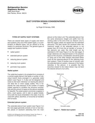
  • 1. TYPES OF SUPPLY DUCT SYSTEMS There are several basic types of supply and return duct systems. Any one of the system types, or a com- bination of different types, can be utilized to fit the needs of a particular structure. The general types of supply duct systems include: radial system extended plenum system reducing plenum system reducing trunk system perimeter loop system. Radial system The radial duct system in its simplest form consists of a central supply plenum that feeds a number of indi- vidual branch ducts arranged in a generally radial pattern (see Figure 1). It also can be designed and sized so that each individual run leaving the plenum can feed two or more supply outlets. This is fre- quently the case because of the number of supply outlets required to condition the structure success- fully and the amount of space at the plenum available for takeoffs.The radial system commonly is applied in attics, crawl spaces, and in slab on grade installa- tions (with the ducts embedded in the slab). It can be used with upflow, downflow, or horizontal air handlers and furnaces. Extended plenum system The extended plenum duct system (see Figure 2 on the next page) generally consists of one or two box- like pieces of ductwork extending from the main plenum at the indoor unit. This extended plenum has the same dimensions (height and width) from the starting collar to the end of the run. Branch runs to feed the supply outlets are tapped into the extended plenum(s). The best results are achieved when the maximum length of the extended plenum is not greater than 24 ft from the air handler or furnace. If two plenums are used, this total length can be extended to 48 ft (see Figure 3 on the next page). If longer distances are required based on the physical layout of the structure, consideration should be given to using one of the other designs discussed below (such as the reducing plenum or the reducing trunk duct system). There is another area of concern with the extended plenum system—because of the higher velocities in the plenum, it is possible that the branches closest to the indoor blower may not feed the desired amount of air (cfm). 1 Refrigeration Service Engineers Society 1666 Rand Road Des Plaines, Illinois 60016 DUCT SYSTEM DESIGN CONSIDERATIONS Part 1 by Roger M Hensley, CMS © 2005 by the Refrigeration Service Engineers Society, Des Plaines, IL Supplement to the Refrigeration Service Engineers Society. 630-148 Section 11A Figure 1. Radial duct system
  • 2. 2 Figure 2. Extended plenum duct system (single plenum) Figure 3. Extended plenum duct system (double plenum) ACCA
  • 3. Never start a branch run from the end cap of an ex- tended plenum. For best results, the starting collar of a branch run should never be any closer than 24 in. from the end cap. To sum up, observe the following general rules for the extended plenum system: Single plenums should not exceed 24 ft in length. Double plenums should not exceed 48 ft in total length. Keep branch run starting collars 24 in. from the end caps. Never locate a takeoff in the end cap. Reducing plenum system The reducing plenum duct system (see Figure 4) can be used when the physical size or layout of the struc- ture calls for greater distances than the length con- straints imposed on the extended plenum (24 ft). The concept of the reducing plenum system is simple— when the air velocity lost to the branch runs reaches approximately 50%, the plenum size is reduced to regain the velocity in the remaining portion of the plenum. This reduction also improves the air flow characteristics at the branch ducts that are closest to the air-handling unit.The 50% rule is demonstrated in Figure 5 on the next page. Note that at the start of the plenum, there is an available air volume of 1,200 cfm and an available velocity of 900 ft/min. After the third branch run, a total of 600 cfm has been distributed to the branches and the velocity in the plenum has been reduced to 450 ft/min. These conditions indicate that the proper location for the reduction in the plenum is after the third branch. The outlet side of the reduction is sized to restore the velocity in the plenum to approximately 900 ft/min. This system is relatively easy to fabricate and install. Additional sheet metal sometimes is required to build the system, but if done correctly it can deliver good results. It may be necessary to balance the system branch dampers properly. Reducing trunk system The reducing trunk duct system (see Figure 6 on the next page) is very similar to the reducing plenum 3 ACCA Figure 4. Reducing plenum duct system
  • 4. system, with the exception that the trunk run is reduced in size after each branch takeoff. These mul- tiple reductions make it possible to maintain a con- stant velocity (ft/min) in the trunk even though the total air volume is reduced as each branch is sup- plied. This type of system generally takes more sheet metal to build and requires more labor to fabricate and install. Another major concern is that there are more joints to seal (to pre- vent air leakage). The reducing trunk system also can be applied using lengths of round duct and manufactured fittings. Round duct systems can signifi- cantly reduce the cost of labor for fabri- cation and installation, and produce very satisfactory results if properly applied. Another configuration that may be used in some cases is known as the primary- secondary trunk system (see Figure 7). This type of system has a primary trunk and two or more secondary trunks. The “tee” fitting located at the end of the pri- mary trunk in this system performs the same function as the reduction in the reducing trunk system. Each secondary trunk has a cross-sectional area that is smaller than that of the primary trunk. The secondary trunks are sized to deliver the proper air volume to each branch at the proper velocity. This type of system can be used very successfully in a structure that spreads out in two or more directions. 4 Figure 5. Reducing plenum “50% rule” Figure 6. Reducing trunk duct system ACCA
  • 5. Perimeter loop system The perimeter loop duct system (see Figure 8 on the next page) is well-suited for buildings that are constructed using concrete slab on grade. It generally per- forms better than the radial system in such applications, especially in cold cli- mates. However, the perimeter loop sys- tem does have the disadvantage of being a little more difficult to design and more expensive to install. It is basically laid out around the perimeter of the structure next to the edge of the slab. The entire perimeter loop is the same size duct. The loop is fed by four or more ducts radiating out from the central plenum. They are usually the same size as the loop duct. The boot boxes are sized to deliver the proper cfm to each room of the structure. SUPPLY DUCT SYSTEM LOCATIONS Decisions regarding the location of a supply air dis- tribution system should be made based on the winter design temperature for the structure’s geographic location.Table 1 in ACCA’s Manual J lists design con- ditions for locations in the U.S. and Canada. This information should be consulted to ensure that the proper type and location of duct system is selected for the structure in question. The ASHRAE Funda- mentals Handbook contains HVAC design criteria for most countries around the world. The general guidelines state that if the winter design temperature for the location of the structure is above 35°F, then both perimeter floor and ceiling distribu- tion systems will provide satisfactory results. If the winter design temperature for the location of the structure is below 35°F, the ceiling distribution sys- tem is not recommended and the floor distribution system should be considered. A modified type of ceil- ing distribution system can be used if the registers are moved closer to the outside walls and the primary air is directed out of the occupied zone and toward the window and door openings. There are six basic locations for supply duct systems in residential structures. Most residential structures can accommodate one or more of these configura- tions. One of the most important jobs of the designer is to select the type of installation that best suits the air distribution requirements of the structure and the needs and desires of the customer. This must be bal- anced with the cost of the installation and the comfort conditions within the structure.The six basic locations for supply duct systems are as follows: attic installations basement installations between floors of multistory structures crawl space installations conditioned space installations embedded in concrete slab. Attic installations Attic installations lend themselves readily to all of the duct system types. A duct system located in an attic must be insulated and must have a vapor barrier installed to prevent condensation on the exterior of 5 Figure 7. Primary-secondary trunk system ACCA
  • 6. the ductwork. Condensation can cause corrosion and rusting of the duct system and possible structural damage to the ceilings. All joints and side seams must be sealed to prevent duct leakage. Some local codes do not permit the use of duct tape as a sealant. In these cases, waterproof mastic must be used. Depending on the type of equipment being used, the air handler or furnace may be installed in the attic space, in the garage area, or in an alcove or closet in the interior of the structure. A packaged unit located outside the structure can be installed on the roof, on the ground, or on a stand raised above ground level. Special insulation and waterproofing must be applied to all ductwork that is exposed to outdoor weather conditions. The air handler should be located where the shortest duct runs possible are attained. The shorter the duct runs are, the lower the resistance to air flow and the lower the heat gains and heat losses will be. One dis- advantage to locating the air handler in the attic space is serviceability. Provisions for service access must be provided. Most local codes require a floored walkway from the attic entry to the unit. A floored area must extend at least 3 ft on all sides of the unit to provide a platform for service work. Another consideration to take into account when the furnace or air handler is installed in an attic is the requirement for an auxiliary drain pan, along with a condensate line and/or emer- gency float switch to shut down the system in case of a condensate overflow. Locating the return air filter grilles in the conditioned space is recommended with attic installations. This allows the homeowner to change the filters without having to enter the attic. The duct system types that lend themselves to attic installations include the extended plenum, the reduc- ing trunk, and the radial arrangements. A wide vari- ety of duct materials can be used with attic installations. However, great care must be taken when installing a flexible duct system. Improper installation that allows sagging, sharp bends, kinks, and crimping of flexible duct will increase the friction loss of the system and increase the total amount of static pressure that the indoor blower must over- come. This can result in service problems and possi- ble equipment failure. It is always necessary to follow the recommendations of the manufacturer when installing a system utilizing flexible duct products. Basement installations Basement installations also lend themselves to all of the duct system types. A basement system must be insulated and must have a vapor barrier installed to prevent condensation on the exterior of the ductwork if the basement is to be unconditioned. If the base- ment is to be conditioned, then the ductwork is con- sidered to be in a conditioned space and insulation may not be required. However, it is recommended that a duct liner be installed for sound attenuation. All joints and side seams must be sealed to prevent duct leakage. Again, be aware that some local codes do not permit the use of duct tape as a sealant. In these cases, waterproof mastic must be used. The air han- dler or furnace may be installed in the basement, or outside the structure if a packaged unit is to be installed. Any ductwork exposed to outdoor weather conditions must be specially treated with insulation and waterproofing. As in an attic installation, the air handler should be located where the shortest duct runs possible are attained. One advantage to locating the air handler in the basement is serviceability. Return air filters may be located at the unit in a basement installation, or filter grilles in the conditioned space may be used. 6 Figure 8. Perimeter loop duct system
  • 7. The duct system types best-suited to basement installations are the extended plenum and the reduc- ing trunk arrangements. Due to headroom and appearance considerations, the radial duct system does not always lend itself to basement installations, although it can be used in some cases. All types of duct materials can be used with base- ment installations. However, flexible duct materials are discouraged, largely because of the appearance and the problem of providing proper support. Sag- ging ductwork will increase the friction loss of the system and increase the total amount of static pres- sure that the indoor blower must overcome, resulting in service problems and even equipment failure. Between floors of multistory structures Between-floor installations usually are installed in fir- down areas, with branch ducts running between the combination ceiling/floor joists. These systems gener- ally are constructed of lined sheet metal. Sometimes duct board is used for sound and noise control. Between-floor ductwork normally does not require insulation, since it is located within the conditioned space. Ductwork that passes through an uncondi- tioned space must be insulated and must have a vapor barrier installed to prevent condensation from accumulating on the exterior of the ductwork. All joints and side seams must be sealed to prevent duct leak- age. If local codes do not permit the use of duct tape as a sealant, waterproof mastic must be used.The air handler or furnace may be installed in a garage, in an interior alcove or closet as permitted by local codes, or, if a packaged unit is to be installed, outside the structure. Any ductwork located outside the structure must be specially treated with insulation and water- proofing if exposed to outdoor weather conditions. The air handler should be located where the shortest duct runs possible are attained. One of the major advantages of a between-floor installation is that the heat gains and losses often associated with ductwork are negated because the ductwork is in the condi- tioned space. With this type of installation, return air filters may be located at the unit, or filter grilles in the conditioned space may be used. The reducing trunk and the extended plenum config- urations are the most common types of duct systems installed between the floors of the multistory struc- tures. Many types of duct materials can be used with between-floor installations. However, flexible duct materials generally are discouraged because they are not as durable as metal ductwork. Once the duct system is installed, it is a major project to make repairs if needed. Crawl space installations Crawl space installations are adaptable to all of the duct system types. A crawl space system must be insulated and must have a vapor barrier installed to prevent condensation on the exterior of the ductwork. All joints and side seams must be sealed to prevent duct leakage. If local codes do not permit the use of duct tape as a sealant, waterproof mastic must be used. The air handler or furnace may be installed in the crawl space, in the garage area, in the interior of the structure as permitted by local codes, or, if a packaged unit is to be installed, outside the structure. The air handler should be located where the shortest duct runs possible are attained. The main disadvan- tage to locating the air handler or furnace in the crawl space is serviceability. Provisions for service access must be made. With crawl space installations, return air filter grilles in the conditioned space should be used. The duct system types that lend themselves to crawl space installations include the extended plenum, the reducing trunk, the radial, and the perimeter loop arrangements. Although many types of duct materi- als can be used in crawl space installations, flexible duct materials are discouraged due to the problem of providing proper support for the ductwork. Conditioned space installations Some basement installations, installations between floors, and fir-down duct systems can be considered “conditioned space” installations. Each of these types of systems has its own considerations, previously dis- cussed. Generally speaking, duct systems that are installed within a conditioned space do not require thermal insulation to prevent heat loss and heat gain. It is desirable, however, to use duct materials such as duct liners or duct board systems constructed prop- erly for sound attenuation. In warm, moist climates, 7
  • 8. duct systems installed in conditioned spaces may need to be insulated to prevent condensation from forming on the exterior surfaces of the ductwork and causing mold, mildew, and structural damage. The most common types of duct systems applied to con- ditioned space installations are the extended plenum and the reducing trunk arrangements. Both the extended plenum and the reducing trunk systems fre- quently are installed in fir-down areas above hallways, cabinets, and closets. They typically are associated with the high inside wall type of supply outlets. Embedded in concrete slab Different types of construction present different prob- lems for system designers and installers. In climates where the average winter temperature is below 35°F, slab on grade construction is used. The floor distrib- ution duct system must be embedded in the slab, which can create several challenges for the designer/installer. Most codes require that the duct system in such cases be installed above the final lot grade. If metal duct material is to be used, it must be treated to prevent rust and corrosion and completely encased in a minimum of 2 in. of concrete grout. Fail- ure to treat the metal duct properly can lead to the failure of the duct system due to rust and corrosion. In areas where the ground water table is high or proper drainage is not ensured, the collapse of the duct system can occur in as little as five years. When this happens, the system usually must be abandoned and the supply duct system must be installed in some other location (e.g., in the ceiling). It also means filling the outlet boots with concrete and most likely replacing the flooring materials in the structure. Needless to say, this is a very expensive and time-consuming undertaking—one that is not possible in some multistory structures without major remodeling work. Sometimes the floor must be removed completely so that repairs can be made. The duct system must be graded back toward the supply air plenum for drainage and removal of any ground water that may enter the duct system. The best way to avoid such problems is to make sure that the design and installation are right the first time. PVC duct materials offer a large advantage over metal in this type of system installation. PVC duct systems do not need to be encased in concrete grout or treated for corrosion, but they still must be graded back toward the plenum for ground water removal and installed above the final lot grade. A wide selec- tion of fittings, boots, and plenums constructed from PVC materials is available today. When PVC duct materials are used, all joints are glued, thus creating a water-resistant duct system. (Some codes do not allow for the use of screws in the assembly of PVC duct systems.) Another factor that is sometimes a detractor to the embedded slab system is the code requirement stip- ulating that the duct system must be installed above the final grade. The builder may be required to increase the foundation stem wall height from the nor- mal 16 in. to 20 to 24 in. to accommodate the duct system installation. In some areas, builders may resist this additional expense in the cost of the structure. The boot boxes and terminal devices used with an embedded concrete slab system should be located under or near doors and windows. They must dis- charge into the unoccupied space of the room to pre- vent the primary airstream from coming in contact with the room’s occupants. The number of outlets for each room depends on the room’s usage, its physi- cal layout, cfm requirements, and the heating and cooling loads as determined by a room-by-room load calculation. When a floor distribution system is used, it is always a good idea to be mindful of furniture placement in the room. The main goal of good system design is to have the outlets discharging into the unoccupied zone of the room. The “occupied zone” of a room is generally defined as the volume of space that exists between the floor and 6 ft above the floor in the ver- tical direction, and is 2 ft or more from the walls in the horizontal direction (see Figure 9). Outlets should not be placed where room furnishings will cover them. This may require having multiple outlets in some rooms to ensure that the distribution air being delivered matches the load. SUPPLY AIR OUTLET LOCATIONS One of the most critical tasks in the design of an air distribution system is the selection of the proper type and proper placement of the supply outlets. The designer must select locations that will deliver the 8
  • 9. conditioned air into the space to be conditioned in such a way that the high heat gain/heat loss load areas (doors and windows) are covered by the pri- mary airstream. In addition, the secondary air (room air) must mix with the primary airstream to ensure even temperatures throughout the room. The design should accomplish these objectives while keeping the primary airstream from entering the occupied zone within the room. By delivering the primary air into the unoccupied zone of the room and mixing it with the secondary air, the designer ensures that the primary airstream does not come in direct contact with the room occupants. If the primary airstream is allowed to come in contact with the room occupants, the result will be complaints of drafts and the overall comfort of the occupants will suffer. In most cases (depending on the location of the duct system and the location of the outlet), this problem is next to impossible to solve without the investment of major time and expense. The best time to prevent this potential problem is when the system is being designed and installed. There are several specifications listed in the engi- neering tables for outlet devices that are very impor- tant to the designer. They include: face velocity—the velocity of the air leaving the outlet, measured in ft/min cfm—the volume of air that the outlet device delivers as a result of the face velocity (“cfm” stands for cubic feet per minute) noise criteria (NC)—a measure of the air noise associated with the outlet device pressure loss—the amount of pressure loss associated with the outlet device, measured in in. w.g.) spread—the width of the primary air envelope measured at the point of terminal velocity terminal velocity—the velocity of an airstream at the end of its throw, measured in ft/min throw—the distance from the face of the outlet that the air travels before reaching terminal velocity AK factor (effective area)—the calculated area of the outlet device based on the average measured velocity between the fins drop—the vertical distance between the base of the outlet and the bottom of the airstream at the end of the horizontal throw. In addition, you should be familiar with the following terms: diffuser—an outlet that discharges supply air in a spreading pattern grille—a louvered covering for an opening through which air passes register—a grille equipped with a damper or a control valve that directs air in a nonspreading jet. Floor locations Grilles and registers installed in the floor should be located in the unoccupied zone of the room. They should be positioned to cover high load areas, such as door and window locations. As mentioned previ- ously, consideration also must be given to the place- ment of furniture within the room.The selection of the 9 Figure 9. “Occupied zone” of a room
  • 10. proper grille or diffuser (outlet device) is one of the designer’s more critical tasks. The outlet device must be selected to deliver the required air volume (cfm) at the correct velocity (ft/min) to condition the space. Ceiling location (center of room) There are basically two different types of ceiling out- let locations. The first is in the center of the room, with the directional pattern of the device being essen- tially circular. This type of installation may work well for cooling-only applications—however, it is one of the poorest selections for heating systems. In the heating season, higher velocities of the conditioned air must be attained in order to force the heated air down into the conditioned space. Higher noise levels will accompany the higher discharge velocities required from the outlet. If the winter design temper- ature is below 35°F, this type of delivery outlet device is not recommended for systems that will be used in the heating season. Ceiling location (modified) The second type of ceiling outlet is one that is moved away from the center of the room and out toward the exterior wall. The discharge is directed toward the high load areas of the room (doors and windows).The location of the outlet must be determined by studying the manufacturer’s engineering data supplied for the selected outlet device. The outlet device should be selected to deliver the required amount of air (cfm) at the proper velocity (ft/min), with an acceptable throw to match the room heat loss/heat gain. It is recommended that the pri- mary air envelope (air moving faster that 35 ft/min for heating and faster than 50 ft/min for cooling) from the outlet not be allowed to come in contact with the room occupants. For example, let’s assume that the room cfm require- ment is 200 cfm. Due to the physical characteristics of the room, it is determined that the best solution is to install two outlets to cover the high load areas (there is a large amount of glass in the room). The designer selects two outlet devices, each of which will deliver 100 cfm at a face velocity that meets the noise criteria (for residential structures, normally NC35 or below). Depending on the outlet device selected, a face velocity of 500 to 750 ft/min generally is accept- able for residential structures. The outlet devices selected will deliver 100 cfm at 600 ft/min, with a noise level of NC30. The throw at these conditions is shown in engineering data to be 6.5 ft at a terminal velocity of 35 ft/min for heating and 8.5 ft at 50 ft/min for cooling. The terminal velocity listed for heating is the most critical. Most people are more sensitive to drafts during the heating season, and more tolerant of air movement during the cooling season. To locate the position of the outlet so that the primary airstream does not come in contact with the room occupants, the designer’s first task is to make sure that the primary airstream is directed toward the unoccupied zone of the room. Chairs and other room furnishings sometimes can be placed in the unoccu- pied zone. The primary air envelope, therefore, should not move down the wall past the 4 to 5-ft level. For example, assume that the ceiling height is 8 ft. The terminal velocity for the selected outlet device is 6.5 ft for heating. If you start at the 5-ft level on the exterior wall and measure up the wall and across the ceiling 6.5 ft, the location of the outlet will be 3.5 ft from the wall to the center of the outlet. The primary air envelope (air moving faster than 35 ft/min) will terminate at the 5-ft level on the exterior wall. A ceiling supply system designed and installed in this manner can be used successfully in areas where the winter design temperatures are below 35°F. This out- let design approach can be utilized with all of the duct system types used in ceiling distribution systems. High inside wall locations A high inside wall outlet system delivers air into the conditioned space from the interior walls. The selec- tion of the outlet device, which is very similar to the procedure described above for modified ceiling loca- tions, is critical to a successful system. This type of delivery normally is associated with fir-down duct systems. Again, the designer must select the outlet device that will deliver the required volume of air (cfm) at the proper velocity (ft/min) to condition the space. The velocity becomes even more critical with this type of delivery system, because the airstream must be directed across the ceiling all the way to the exterior 10
  • 11. wall and part way down the wall to provide coverage of the high load areas in the room. If the room is 20 ft wide, the outlet device must be selected with a throw of more than 20 ft in order to guarantee that the primary airstream will remain in the unoccupied por- tion of the room. If the selected device does not have sufficient throw, the primary airstream will drop into the occupied zone of the room and comfort condi- tions will suffer. The throw and drop characteristics are very important to the successful application of this type of supply outlet. Unless a high-quality outlet device is used, noise problems with this type of delivery system can be very common. The outlet device selected should have adjustable deflection vanes and should be equipped with a damper for volume control and bal- ancing (a register). The noise criteria specifications for the register should be in the range of NC30 to 35. RETURN AIR DUCT SYSTEMS The return air duct system is just as important as the supply system, and too often it is largely ignored. In many cases, the return system consists of one or two improperly sized openings connected back to the air handler through improperly sized return ducts or through wall, floor, and ceiling framing cavities. Although panned framing members can be used for return systems, they generally should be avoided. These types of installations are next to impossible to seal. Air leaking into the system can cause additional sensible and latent loads on the HVAC system and lead to comfort complaints from the occupants of the structure. Duct leakage If duct leakage occurs in the attic space during the cooling season, warm, moist air can be pulled into the return, resulting in an increase in both the latent load and the sensible load on the HVAC system. This infiltration into the return system will be aggravated if the return system is undersized. For example, con- sider a 3-ton system that requires 450 cfm per ton for cooling (1,350 cfm). Assume that the return is improperly sized and can handle only 1,000 cfm. Due to the undersizing of the return and the available sta- tic pressure of the blower, the blower will try to pull air from the attic space if leaks are present in the duct system. If the leaks are large enough in the return system, the 350-cfm shortfall will be drawn from the high-temperature air in the attic. In some areas, attic temperatures can reach 140 to 150°F db (dry bulb) even if the attic is vented properly. Under these con- ditions, the mixed air temperature entering the evap- orator coil will be 91.9 to 96.9°F db, instead of the normal 75 to 80°F db. For most systems, the ∆T across the evaporator is 18 to 20°F db, which means that in this case the air leaving the evaporator will be 73.9 to 76.9°F db instead of the normal 55 to 60°F db. If the relative humidity of the air in the attic is high, it also will increase the latent load on the evaporator and degrade the system’s capacity to maintain the desired comfort conditions in the structure. As a general rule, when framing members are used as part of the return air duct system, the following approximate cfm values are recommended: 2 × 4s on 16-in. centers = 150 cfm 2 × 4s on 24-in. centers = 200 cfm 2 × 6s on 16-in. centers = 210 cfm 2 × 6s on 24-in. centers = 340 cfm 2 × 8s on 16-in. centers = 340 cfm 2 × 8s on 24-in. centers = 560 cfm 2 × 10s on 16-in. centers = 500 cfm 2 × 10s on 24-in. centers = 800 cfm 2 × 12s on 16-in. centers = 700 cfm 2 × 12s on 24-in. centers = 1,020 cfm The approximate cfm values listed here are based on the true net free areas. They do not take into account the complications encountered with sealing cavities against air infiltration and other problems discussed above. If the return air duct system is located in the crawl space of the structure and panned joists are used for the return system, duct leakage can add a large latent load on the HVAC system, resulting in reduced sensible heat removal capacity and increased oper- ating costs for the homeowner. Complaints about the comfort conditions within the structure are also likely. As you can see, a properly sized, sealed return duct system is just as important as a properly sized, sealed supply duct system in ensuring that the com- fort conditions within the structure are maintained in an economical manner. 11
  • 12. CENTRAL RETURN SYSTEMS Central return systems can be applied in smaller structures with success. These systems consist of one or more return inlets, strategically located within the structure and sized to return the total amount of the supplied air volume to the indoor blower. Both the inlet box and the return connecting ductwork should be sized where the room air will flow back to the blower at a relatively low velocity. As emphasized above, the return duct system must be free of leaks. It is sometimes desirable to have some turns or other fittings in the duct run in order to prevent blower noise from being transmitted down the duct and exiting the return air grille.The return air box should be lined with sound attenuation insulation and insulated on the outside to prevent or retard heat gain and heat loss. Air delivered to all rooms of the structure should have an unrestricted path back to the return grille. This means that closed doors must not isolate a room. The most common method seen in construction today is to undercut the doors, thus allowing air to pass under a door if it is closed. The amount of the undercut is determined by using the same methods as those used to size the return grille or the connect- ing return duct—that is, when the door is closed, there must be adequate free area to ensure that the room does not become pressurized. If a room is allowed to become pressurized, the delivery of the supply air will be impeded, comfort conditions in the room will suffer, and the exfiltration of room air will occur. Assume, for example, that the room in ques- tion has a cfm requirement of 200 cfm and a 32-in. entry door. Based on a design friction loss factor for the return system of 0.05 in. w.g., the opening at the bottom of the door would need to be approximately 3 in. of “free” space (excluding any floor coverings) in order to ensure a proper return air flow from the room. A better solution would be to install a boot sleeve above the door and nonvision (non-see- through) transfer grilles on either side, or install non- vision transfer grilles in the door itself (a 12-in. × 8-in. transfer grille would be required in this case). Larger structures require multiple returns in order to achieve satisfactory results. Each of the returns must be sized to return the amount of air delivered to the rooms or zones where the return grille is located. It is worth repeating that the return system must be capable of handling the same amount of air as that delivered by the supply side of the system. INDIVIDUAL ROOM RETURN SYSTEMS In some structures it may be desirable to install indi- vidual room returns. Of course, this means that the return system is just as elaborate as the supply sys- tem. Each individual room return is sized to return the same amount of air that is delivered to the room by the supply system.The results are excellent if the lay- out and sizing are done properly—in fact, there is no other return system that performs as well as the indi- vidual room return system. The major drawback to this approach is the initial cost. SUMMARY It is the goal of this document to offer an overview of the general principles of duct system design and to call attention to some of the special considerations that need to be given to the process to ensure a sat- isfactory result. The ultimate objective is to provide a dependable system that not only serves the needs of the consumer, but also increases profits for the installing contractor by reducing callbacks. Refrigeration Service Engineers Society 1666 Rand Road Des Plaines, IL 60016 847-297-6464