SlideShare a Scribd company logo
1 of 14
The L-Network L C R source R load L-networks are used to match the output impedance of one circuit to the input of another. R source  < R load , 1< Q < 5 L C R source R load R source  > R load , 1 < Q < 5
The Pi-Network L C2 R source R load The pi-network is also used for impedance matching, with a high source impedance and a low load impedance. Often used in vacuum tube RF power amps to match low-impedance antennas. C1 R source  > R load , 5 < Q < 15
Filters Filters are an integral part of any radio transmitter or receiver. They are used to selectively pass only certain frequencies through the circuits of the radio. Insertion Loss 0 db 60 db frequency Insertion Loss 0 db 60 db frequency Insertion Loss 0 db 60 db frequency Insertion Loss 0 db 60 db frequency High-pass filter Low-pass filter Band-pass filter Band-stop filter 3 db f C f C 3 db f C 3 db f C 3 db
LC Filters L2 C3 C1 C5 L4 L1 C2 C4 L3 L5 Five-element low-pass filters L2 C1 L4 C3 C5 L3 C2 L5 C4 L1 Five-element high-pass filters
Filter Response Functions Filter designs are based on mathematical functions which exhibit filter-like behavior when plotted versus frequency. Two types of response functions are prevalent. The first is the  Butterworth  response, which exhibits high attenuation and a flat passband but is a poor approximation for both pass and stop bands near cutoff.  The other type of response function is the Chebyshev response. It exhibits a “ripple” in the passband but provides a better model of the filter near the cutoff. Tables have been built for both types of filters which give values for L and C for various LC filter configurations. These tables are scaled as needed for particular frequencies and other properties.
Low-Pass Filter Design Taken from ARRL Handbook, 1997, p. 16.14 copyright 1996 ARRL. Standard tables have been created which allow for the simple calculation of appropriate L and C values to obtain a filter with the desired properties. The first step is to select a filter design which gives the proper attenuation. Here, the frequency multiples (of the cutoff frequency) are given at which various attenuation levels are achieved for various filter designs. If 30 dB attenuation is desired at twice the cutoff frequency, a five-element design with a reflection coefficient (RC) of 10% or greater can be used.
Low-Pass Filter Design Taken from ARRL Handbook, 1997, p. 16.12 copyright 1996 ARRL. Once the design has been chosen, the normalized element values are taken from another table. These are then scaled to arrive at the desired filter element L and C values.
Low-Pass Filter Design For a 5-element filter with a reflection coefficient of 10%, our normalized element values are: C1=C5=0.9732 L2=L4=1.372 C3=1.803 Now we calculate scaling factors for C and L for the desired cutoff frequency and input/output impedance using the following equations: For a frequency of 7.3 MHz and an impedance of 50 ohms, we get C S =4.36x10 -10  and LS=1.09x10 -6 . These factors are then multiplied by the values of C and L from the table to get the values which result in the desired filter properties: C1 = C5 = 0.9732 x 436 pF = 424.3 pF C3 = 1.372 x 436 pF = 598.2 pF L2 = L4 = 1.803 x 1.09   H = 2.0   H
Band-Pass Filter Design L2 C3 C1 C5 L4 L3 L1 C2 L5 C4 The filter design tables can serve as the starting point for designing band-pass filters. The approach is to design a low-pass filter whose cutoff frequency is the desired bandwidth of the band-pass filter. Then the low-pass filter capacitors are combined with inductors, and  the low-pass filter inductors are combined with capacitors, such that the resulting configuration is sets of series and parallel LC circuits resonant at the desired bandpass frequency. In the filter below, C1, L2, C3, L4, and C5 make up the original low-pass filter. Elements L1, C2, L3, C4, and L5 have been added to make this a bandpass filter. Note that the L and C combinations are parallel where the original elements were in parallel, and are series where the original elements were in series.
Crystal Ladder Filters C12 C23 Y1 Y2 Y3 For band-pass filters, the Q of the filter elements limits the minimum-achievable bandwidth of the filter. If crystals are used in place of other elements, their very-high Q values allow filters to be built which have very narrow bandwidths. L S C S R S C P The equivalent circuit for a crystal is shown at right. L S , C S , and R S  are called the motional inductance, capacitance, and resistance of the crystal. C P  is the parallel plate capacitance due to the two electrodes of the crystal and the quartz dielectric between them. It is easy to see that each crystal forms a tuned circuit, and using them in a crystal ladder filter results in a configuration much like the previously-discussed band- pass filter, but with a narrower bandpass because of the higher Q of the crystals.
SW+ Receiver Antenna Input Circuits copyright 1998 Dave Benson NN1G Signals from the antenna are passed to the receiver after they pass through the low-pass filter. They pass through a band-pass filter made up of C40 and RFC3. Diodes D7 through D10 serve to limit the voltage swings seen by the receiver when the transmitter is operating, and to “break up” the resonance of C40 and RFC3. This serves to limit the signal from the transmitter which is seen by the receiver. The signal next passes through the 5k-ohm potentiometer which serves as the RF gain control. Transformer T1 is configured as a tuned circuit. The output from the transformer to the receive mixer is taken from the center tap of the transformer this time so as to better match the impedance of the antenna (low) with the input impedance of the mixer (high). The mixer is powered by the 8-volt regulated voltage, and the antenna signal is mixed with the 3-MHz VFO signal to obtain the signal at an IF of 4 MHz.
Receiver First Mixer & Filter The output from the receive mixer is fed to a crystal ladder filter. C11 and RFC1 make up an L-network which matches the impedance of the mixer output to the impedance of the crystal filter. C12 and C15 serve to pull the resonant frequencies of Y1 and Y3 up a bit as needed by the filter design. The crystal filter has a narrow bandpass (probably about 1 kHz or so). This serves to pass only a narrow range of signals to subsequent stages in the receiver. Circuit copyright 1998 Dave Benson NN1G
Construction Part 1 ,[object Object],[object Object],[object Object],[object Object],[object Object],[object Object],[object Object],[object Object],[object Object],[object Object],[object Object],[object Object],[object Object]
Construction Part 2 ,[object Object],[object Object],[object Object],[object Object],[object Object],[object Object],[object Object],[object Object],[object Object],[object Object]

More Related Content

What's hot

Filters and Tuned Amplifiers
Filters and Tuned AmplifiersFilters and Tuned Amplifiers
Filters and Tuned Amplifiersselarothitc
 
7.Active Filters using Opamp
7.Active Filters using Opamp7.Active Filters using Opamp
7.Active Filters using OpampINDIAN NAVY
 
Op amp applications filters cw
Op amp applications filters cwOp amp applications filters cw
Op amp applications filters cwJUNAID SK
 
Op amp applications filters cw final
Op amp applications filters cw finalOp amp applications filters cw final
Op amp applications filters cw finalJUNAID SK
 
Op amp applications filters cw final (2)
Op amp applications filters cw final (2)Op amp applications filters cw final (2)
Op amp applications filters cw final (2)JUNAID SK
 
Filter circuits slide_share
Filter circuits slide_shareFilter circuits slide_share
Filter circuits slide_shareSMITHAS35
 
Practical Active Filter Design
Practical Active Filter Design Practical Active Filter Design
Practical Active Filter Design Sachin Mehta
 
Design and Analysis of Active Bandpass Filter
Design and Analysis of Active Bandpass FilterDesign and Analysis of Active Bandpass Filter
Design and Analysis of Active Bandpass FilterKyla Marino
 
Passive electrical filters
Passive electrical filtersPassive electrical filters
Passive electrical filtersJawad Khan
 

What's hot (20)

Filters and Tuned Amplifiers
Filters and Tuned AmplifiersFilters and Tuned Amplifiers
Filters and Tuned Amplifiers
 
7.Active Filters using Opamp
7.Active Filters using Opamp7.Active Filters using Opamp
7.Active Filters using Opamp
 
09 rc filters
09 rc filters09 rc filters
09 rc filters
 
Filter dengan-op-amp
Filter dengan-op-ampFilter dengan-op-amp
Filter dengan-op-amp
 
Active filter
Active filterActive filter
Active filter
 
Op amp applications filters cw
Op amp applications filters cwOp amp applications filters cw
Op amp applications filters cw
 
Low pass filters
Low pass filtersLow pass filters
Low pass filters
 
Filters
FiltersFilters
Filters
 
Op amp applications filters cw final
Op amp applications filters cw finalOp amp applications filters cw final
Op amp applications filters cw final
 
Active Filters
Active FiltersActive Filters
Active Filters
 
Filters
FiltersFilters
Filters
 
Op amp applications filters cw final (2)
Op amp applications filters cw final (2)Op amp applications filters cw final (2)
Op amp applications filters cw final (2)
 
Filter circuits slide_share
Filter circuits slide_shareFilter circuits slide_share
Filter circuits slide_share
 
Filter circuit (ALIV - BANGLADESH)
Filter circuit (ALIV - BANGLADESH)Filter circuit (ALIV - BANGLADESH)
Filter circuit (ALIV - BANGLADESH)
 
Practical Active Filter Design
Practical Active Filter Design Practical Active Filter Design
Practical Active Filter Design
 
Filters
FiltersFilters
Filters
 
Active filters
Active filtersActive filters
Active filters
 
Design and Analysis of Active Bandpass Filter
Design and Analysis of Active Bandpass FilterDesign and Analysis of Active Bandpass Filter
Design and Analysis of Active Bandpass Filter
 
Passive electrical filters
Passive electrical filtersPassive electrical filters
Passive electrical filters
 
11 hp filter
11 hp filter11 hp filter
11 hp filter
 

Viewers also liked

Receiving end circle diagram
Receiving end circle diagram Receiving end circle diagram
Receiving end circle diagram GPERI
 
Tarrif and load curves
Tarrif and load curvesTarrif and load curves
Tarrif and load curvesGPERI
 
Low-Pass Filter Design using Microstrip
Low-Pass Filter Design using MicrostripLow-Pass Filter Design using Microstrip
Low-Pass Filter Design using MicrostripSarvajeet Halder
 
Ppt on diff. load curve
Ppt on diff. load curvePpt on diff. load curve
Ppt on diff. load curveCraZzy Shubh
 
Load curve
Load curveLoad curve
Load curveboromama
 

Viewers also liked (10)

Hf mobile
Hf mobileHf mobile
Hf mobile
 
Lesson4
Lesson4Lesson4
Lesson4
 
Lesson1
Lesson1Lesson1
Lesson1
 
Hf radio
Hf radioHf radio
Hf radio
 
Receiving end circle diagram
Receiving end circle diagram Receiving end circle diagram
Receiving end circle diagram
 
Tarrif and load curves
Tarrif and load curvesTarrif and load curves
Tarrif and load curves
 
filters
filtersfilters
filters
 
Low-Pass Filter Design using Microstrip
Low-Pass Filter Design using MicrostripLow-Pass Filter Design using Microstrip
Low-Pass Filter Design using Microstrip
 
Ppt on diff. load curve
Ppt on diff. load curvePpt on diff. load curve
Ppt on diff. load curve
 
Load curve
Load curveLoad curve
Load curve
 

Similar to Lesson5

Exp2 passive band pass and band-stop filter
Exp2 passive band pass and band-stop filterExp2 passive band pass and band-stop filter
Exp2 passive band pass and band-stop filterSarah Krystelle
 
5. An analog filer has system fnction Ha(s)--a (a) (10 pts,) Comvert .pdf
5. An analog filer has system fnction Ha(s)--a (a) (10 pts,) Comvert .pdf5. An analog filer has system fnction Ha(s)--a (a) (10 pts,) Comvert .pdf
5. An analog filer has system fnction Ha(s)--a (a) (10 pts,) Comvert .pdfinfo324235
 
Development of a receiver circuit for medium frequency shift keying signals.
Development of a receiver circuit for medium frequency shift keying signals.Development of a receiver circuit for medium frequency shift keying signals.
Development of a receiver circuit for medium frequency shift keying signals.inventionjournals
 
unit-5 2nd part active filters by ACEIT.ppt
unit-5 2nd part active filters by ACEIT.pptunit-5 2nd part active filters by ACEIT.ppt
unit-5 2nd part active filters by ACEIT.pptamitthory13012003
 
2. ELECTRICAL NETWORK_ UNIT 2_chandra Shekhar K
2. ELECTRICAL NETWORK_ UNIT 2_chandra Shekhar K2. ELECTRICAL NETWORK_ UNIT 2_chandra Shekhar K
2. ELECTRICAL NETWORK_ UNIT 2_chandra Shekhar KCHANDRA SHEKHAR
 
resonance/electrical networks
resonance/electrical networksresonance/electrical networks
resonance/electrical networkschandruec026
 
Design of 16 Channel R.F. Mixer
Design of 16 Channel R.F. MixerDesign of 16 Channel R.F. Mixer
Design of 16 Channel R.F. MixerIOSR Journals
 
Lcl filter design
Lcl filter designLcl filter design
Lcl filter designZunAib Ali
 
richard transformation method its used to so many things.ppt
richard transformation method its used to so many things.pptrichard transformation method its used to so many things.ppt
richard transformation method its used to so many things.ppttamizhmaniv2021
 

Similar to Lesson5 (20)

14 activefilters
14 activefilters14 activefilters
14 activefilters
 
Exp2 passive band pass and band-stop filter
Exp2 passive band pass and band-stop filterExp2 passive band pass and band-stop filter
Exp2 passive band pass and band-stop filter
 
5. An analog filer has system fnction Ha(s)--a (a) (10 pts,) Comvert .pdf
5. An analog filer has system fnction Ha(s)--a (a) (10 pts,) Comvert .pdf5. An analog filer has system fnction Ha(s)--a (a) (10 pts,) Comvert .pdf
5. An analog filer has system fnction Ha(s)--a (a) (10 pts,) Comvert .pdf
 
LICA-
LICA- LICA-
LICA-
 
Development of a receiver circuit for medium frequency shift keying signals.
Development of a receiver circuit for medium frequency shift keying signals.Development of a receiver circuit for medium frequency shift keying signals.
Development of a receiver circuit for medium frequency shift keying signals.
 
unit-5 2nd part active filters by ACEIT.ppt
unit-5 2nd part active filters by ACEIT.pptunit-5 2nd part active filters by ACEIT.ppt
unit-5 2nd part active filters by ACEIT.ppt
 
Filters2
Filters2Filters2
Filters2
 
Microwave
MicrowaveMicrowave
Microwave
 
2. ELECTRICAL NETWORK_ UNIT 2_chandra Shekhar K
2. ELECTRICAL NETWORK_ UNIT 2_chandra Shekhar K2. ELECTRICAL NETWORK_ UNIT 2_chandra Shekhar K
2. ELECTRICAL NETWORK_ UNIT 2_chandra Shekhar K
 
Filtros activos - Thomas.pdf
Filtros activos - Thomas.pdfFiltros activos - Thomas.pdf
Filtros activos - Thomas.pdf
 
Bh
BhBh
Bh
 
16971168.ppt
16971168.ppt16971168.ppt
16971168.ppt
 
Oscillator
OscillatorOscillator
Oscillator
 
resonance/electrical networks
resonance/electrical networksresonance/electrical networks
resonance/electrical networks
 
Exp passive filter (6)
Exp passive filter (6)Exp passive filter (6)
Exp passive filter (6)
 
IC Circuits Amplifiers
IC Circuits AmplifiersIC Circuits Amplifiers
IC Circuits Amplifiers
 
Design of 16 Channel R.F. Mixer
Design of 16 Channel R.F. MixerDesign of 16 Channel R.F. Mixer
Design of 16 Channel R.F. Mixer
 
Lcl filter design
Lcl filter designLcl filter design
Lcl filter design
 
Vhf receiver 6m
Vhf receiver 6mVhf receiver 6m
Vhf receiver 6m
 
richard transformation method its used to so many things.ppt
richard transformation method its used to so many things.pptrichard transformation method its used to so many things.ppt
richard transformation method its used to so many things.ppt
 

More from Kavin Paul

3 Basic Electronics 3
3 Basic Electronics 33 Basic Electronics 3
3 Basic Electronics 3Kavin Paul
 
Vision For Life
Vision For LifeVision For Life
Vision For LifeKavin Paul
 
corporate social responsibilty
corporate social responsibiltycorporate social responsibilty
corporate social responsibiltyKavin Paul
 

More from Kavin Paul (7)

Lesson2
Lesson2Lesson2
Lesson2
 
Lesson6
Lesson6Lesson6
Lesson6
 
3 Basic Electronics 3
3 Basic Electronics 33 Basic Electronics 3
3 Basic Electronics 3
 
2 Lec10 2003
2 Lec10 20032 Lec10 2003
2 Lec10 2003
 
14 Lec11 2003
14 Lec11 200314 Lec11 2003
14 Lec11 2003
 
Vision For Life
Vision For LifeVision For Life
Vision For Life
 
corporate social responsibilty
corporate social responsibiltycorporate social responsibilty
corporate social responsibilty
 

Recently uploaded

Advanced Views - Calendar View in Odoo 17
Advanced Views - Calendar View in Odoo 17Advanced Views - Calendar View in Odoo 17
Advanced Views - Calendar View in Odoo 17Celine George
 
Beyond the EU: DORA and NIS 2 Directive's Global Impact
Beyond the EU: DORA and NIS 2 Directive's Global ImpactBeyond the EU: DORA and NIS 2 Directive's Global Impact
Beyond the EU: DORA and NIS 2 Directive's Global ImpactPECB
 
1029 - Danh muc Sach Giao Khoa 10 . pdf
1029 -  Danh muc Sach Giao Khoa 10 . pdf1029 -  Danh muc Sach Giao Khoa 10 . pdf
1029 - Danh muc Sach Giao Khoa 10 . pdfQucHHunhnh
 
Key note speaker Neum_Admir Softic_ENG.pdf
Key note speaker Neum_Admir Softic_ENG.pdfKey note speaker Neum_Admir Softic_ENG.pdf
Key note speaker Neum_Admir Softic_ENG.pdfAdmir Softic
 
Python Notes for mca i year students osmania university.docx
Python Notes for mca i year students osmania university.docxPython Notes for mca i year students osmania university.docx
Python Notes for mca i year students osmania university.docxRamakrishna Reddy Bijjam
 
Russian Escort Service in Delhi 11k Hotel Foreigner Russian Call Girls in Delhi
Russian Escort Service in Delhi 11k Hotel Foreigner Russian Call Girls in DelhiRussian Escort Service in Delhi 11k Hotel Foreigner Russian Call Girls in Delhi
Russian Escort Service in Delhi 11k Hotel Foreigner Russian Call Girls in Delhikauryashika82
 
This PowerPoint helps students to consider the concept of infinity.
This PowerPoint helps students to consider the concept of infinity.This PowerPoint helps students to consider the concept of infinity.
This PowerPoint helps students to consider the concept of infinity.christianmathematics
 
Making and Justifying Mathematical Decisions.pdf
Making and Justifying Mathematical Decisions.pdfMaking and Justifying Mathematical Decisions.pdf
Making and Justifying Mathematical Decisions.pdfChris Hunter
 
Z Score,T Score, Percential Rank and Box Plot Graph
Z Score,T Score, Percential Rank and Box Plot GraphZ Score,T Score, Percential Rank and Box Plot Graph
Z Score,T Score, Percential Rank and Box Plot GraphThiyagu K
 
Activity 01 - Artificial Culture (1).pdf
Activity 01 - Artificial Culture (1).pdfActivity 01 - Artificial Culture (1).pdf
Activity 01 - Artificial Culture (1).pdfciinovamais
 
Seal of Good Local Governance (SGLG) 2024Final.pptx
Seal of Good Local Governance (SGLG) 2024Final.pptxSeal of Good Local Governance (SGLG) 2024Final.pptx
Seal of Good Local Governance (SGLG) 2024Final.pptxnegromaestrong
 
Ecological Succession. ( ECOSYSTEM, B. Pharmacy, 1st Year, Sem-II, Environmen...
Ecological Succession. ( ECOSYSTEM, B. Pharmacy, 1st Year, Sem-II, Environmen...Ecological Succession. ( ECOSYSTEM, B. Pharmacy, 1st Year, Sem-II, Environmen...
Ecological Succession. ( ECOSYSTEM, B. Pharmacy, 1st Year, Sem-II, Environmen...Shubhangi Sonawane
 
Explore beautiful and ugly buildings. Mathematics helps us create beautiful d...
Explore beautiful and ugly buildings. Mathematics helps us create beautiful d...Explore beautiful and ugly buildings. Mathematics helps us create beautiful d...
Explore beautiful and ugly buildings. Mathematics helps us create beautiful d...christianmathematics
 
psychiatric nursing HISTORY COLLECTION .docx
psychiatric  nursing HISTORY  COLLECTION  .docxpsychiatric  nursing HISTORY  COLLECTION  .docx
psychiatric nursing HISTORY COLLECTION .docxPoojaSen20
 
Basic Civil Engineering first year Notes- Chapter 4 Building.pptx
Basic Civil Engineering first year Notes- Chapter 4 Building.pptxBasic Civil Engineering first year Notes- Chapter 4 Building.pptx
Basic Civil Engineering first year Notes- Chapter 4 Building.pptxDenish Jangid
 
Mixin Classes in Odoo 17 How to Extend Models Using Mixin Classes
Mixin Classes in Odoo 17  How to Extend Models Using Mixin ClassesMixin Classes in Odoo 17  How to Extend Models Using Mixin Classes
Mixin Classes in Odoo 17 How to Extend Models Using Mixin ClassesCeline George
 
microwave assisted reaction. General introduction
microwave assisted reaction. General introductionmicrowave assisted reaction. General introduction
microwave assisted reaction. General introductionMaksud Ahmed
 
TỔNG ÔN TẬP THI VÀO LỚP 10 MÔN TIẾNG ANH NĂM HỌC 2023 - 2024 CÓ ĐÁP ÁN (NGỮ Â...
TỔNG ÔN TẬP THI VÀO LỚP 10 MÔN TIẾNG ANH NĂM HỌC 2023 - 2024 CÓ ĐÁP ÁN (NGỮ Â...TỔNG ÔN TẬP THI VÀO LỚP 10 MÔN TIẾNG ANH NĂM HỌC 2023 - 2024 CÓ ĐÁP ÁN (NGỮ Â...
TỔNG ÔN TẬP THI VÀO LỚP 10 MÔN TIẾNG ANH NĂM HỌC 2023 - 2024 CÓ ĐÁP ÁN (NGỮ Â...Nguyen Thanh Tu Collection
 
Role Of Transgenic Animal In Target Validation-1.pptx
Role Of Transgenic Animal In Target Validation-1.pptxRole Of Transgenic Animal In Target Validation-1.pptx
Role Of Transgenic Animal In Target Validation-1.pptxNikitaBankoti2
 

Recently uploaded (20)

Advanced Views - Calendar View in Odoo 17
Advanced Views - Calendar View in Odoo 17Advanced Views - Calendar View in Odoo 17
Advanced Views - Calendar View in Odoo 17
 
Beyond the EU: DORA and NIS 2 Directive's Global Impact
Beyond the EU: DORA and NIS 2 Directive's Global ImpactBeyond the EU: DORA and NIS 2 Directive's Global Impact
Beyond the EU: DORA and NIS 2 Directive's Global Impact
 
1029 - Danh muc Sach Giao Khoa 10 . pdf
1029 -  Danh muc Sach Giao Khoa 10 . pdf1029 -  Danh muc Sach Giao Khoa 10 . pdf
1029 - Danh muc Sach Giao Khoa 10 . pdf
 
Key note speaker Neum_Admir Softic_ENG.pdf
Key note speaker Neum_Admir Softic_ENG.pdfKey note speaker Neum_Admir Softic_ENG.pdf
Key note speaker Neum_Admir Softic_ENG.pdf
 
Python Notes for mca i year students osmania university.docx
Python Notes for mca i year students osmania university.docxPython Notes for mca i year students osmania university.docx
Python Notes for mca i year students osmania university.docx
 
Russian Escort Service in Delhi 11k Hotel Foreigner Russian Call Girls in Delhi
Russian Escort Service in Delhi 11k Hotel Foreigner Russian Call Girls in DelhiRussian Escort Service in Delhi 11k Hotel Foreigner Russian Call Girls in Delhi
Russian Escort Service in Delhi 11k Hotel Foreigner Russian Call Girls in Delhi
 
This PowerPoint helps students to consider the concept of infinity.
This PowerPoint helps students to consider the concept of infinity.This PowerPoint helps students to consider the concept of infinity.
This PowerPoint helps students to consider the concept of infinity.
 
Making and Justifying Mathematical Decisions.pdf
Making and Justifying Mathematical Decisions.pdfMaking and Justifying Mathematical Decisions.pdf
Making and Justifying Mathematical Decisions.pdf
 
Z Score,T Score, Percential Rank and Box Plot Graph
Z Score,T Score, Percential Rank and Box Plot GraphZ Score,T Score, Percential Rank and Box Plot Graph
Z Score,T Score, Percential Rank and Box Plot Graph
 
Activity 01 - Artificial Culture (1).pdf
Activity 01 - Artificial Culture (1).pdfActivity 01 - Artificial Culture (1).pdf
Activity 01 - Artificial Culture (1).pdf
 
INDIA QUIZ 2024 RLAC DELHI UNIVERSITY.pptx
INDIA QUIZ 2024 RLAC DELHI UNIVERSITY.pptxINDIA QUIZ 2024 RLAC DELHI UNIVERSITY.pptx
INDIA QUIZ 2024 RLAC DELHI UNIVERSITY.pptx
 
Seal of Good Local Governance (SGLG) 2024Final.pptx
Seal of Good Local Governance (SGLG) 2024Final.pptxSeal of Good Local Governance (SGLG) 2024Final.pptx
Seal of Good Local Governance (SGLG) 2024Final.pptx
 
Ecological Succession. ( ECOSYSTEM, B. Pharmacy, 1st Year, Sem-II, Environmen...
Ecological Succession. ( ECOSYSTEM, B. Pharmacy, 1st Year, Sem-II, Environmen...Ecological Succession. ( ECOSYSTEM, B. Pharmacy, 1st Year, Sem-II, Environmen...
Ecological Succession. ( ECOSYSTEM, B. Pharmacy, 1st Year, Sem-II, Environmen...
 
Explore beautiful and ugly buildings. Mathematics helps us create beautiful d...
Explore beautiful and ugly buildings. Mathematics helps us create beautiful d...Explore beautiful and ugly buildings. Mathematics helps us create beautiful d...
Explore beautiful and ugly buildings. Mathematics helps us create beautiful d...
 
psychiatric nursing HISTORY COLLECTION .docx
psychiatric  nursing HISTORY  COLLECTION  .docxpsychiatric  nursing HISTORY  COLLECTION  .docx
psychiatric nursing HISTORY COLLECTION .docx
 
Basic Civil Engineering first year Notes- Chapter 4 Building.pptx
Basic Civil Engineering first year Notes- Chapter 4 Building.pptxBasic Civil Engineering first year Notes- Chapter 4 Building.pptx
Basic Civil Engineering first year Notes- Chapter 4 Building.pptx
 
Mixin Classes in Odoo 17 How to Extend Models Using Mixin Classes
Mixin Classes in Odoo 17  How to Extend Models Using Mixin ClassesMixin Classes in Odoo 17  How to Extend Models Using Mixin Classes
Mixin Classes in Odoo 17 How to Extend Models Using Mixin Classes
 
microwave assisted reaction. General introduction
microwave assisted reaction. General introductionmicrowave assisted reaction. General introduction
microwave assisted reaction. General introduction
 
TỔNG ÔN TẬP THI VÀO LỚP 10 MÔN TIẾNG ANH NĂM HỌC 2023 - 2024 CÓ ĐÁP ÁN (NGỮ Â...
TỔNG ÔN TẬP THI VÀO LỚP 10 MÔN TIẾNG ANH NĂM HỌC 2023 - 2024 CÓ ĐÁP ÁN (NGỮ Â...TỔNG ÔN TẬP THI VÀO LỚP 10 MÔN TIẾNG ANH NĂM HỌC 2023 - 2024 CÓ ĐÁP ÁN (NGỮ Â...
TỔNG ÔN TẬP THI VÀO LỚP 10 MÔN TIẾNG ANH NĂM HỌC 2023 - 2024 CÓ ĐÁP ÁN (NGỮ Â...
 
Role Of Transgenic Animal In Target Validation-1.pptx
Role Of Transgenic Animal In Target Validation-1.pptxRole Of Transgenic Animal In Target Validation-1.pptx
Role Of Transgenic Animal In Target Validation-1.pptx
 

Lesson5

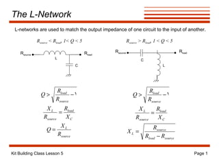
  • 1. The L-Network L C R source R load L-networks are used to match the output impedance of one circuit to the input of another. R source < R load , 1< Q < 5 L C R source R load R source > R load , 1 < Q < 5
  • 2. The Pi-Network L C2 R source R load The pi-network is also used for impedance matching, with a high source impedance and a low load impedance. Often used in vacuum tube RF power amps to match low-impedance antennas. C1 R source > R load , 5 < Q < 15
  • 3. Filters Filters are an integral part of any radio transmitter or receiver. They are used to selectively pass only certain frequencies through the circuits of the radio. Insertion Loss 0 db 60 db frequency Insertion Loss 0 db 60 db frequency Insertion Loss 0 db 60 db frequency Insertion Loss 0 db 60 db frequency High-pass filter Low-pass filter Band-pass filter Band-stop filter 3 db f C f C 3 db f C 3 db f C 3 db
  • 4. LC Filters L2 C3 C1 C5 L4 L1 C2 C4 L3 L5 Five-element low-pass filters L2 C1 L4 C3 C5 L3 C2 L5 C4 L1 Five-element high-pass filters
  • 5. Filter Response Functions Filter designs are based on mathematical functions which exhibit filter-like behavior when plotted versus frequency. Two types of response functions are prevalent. The first is the Butterworth response, which exhibits high attenuation and a flat passband but is a poor approximation for both pass and stop bands near cutoff. The other type of response function is the Chebyshev response. It exhibits a “ripple” in the passband but provides a better model of the filter near the cutoff. Tables have been built for both types of filters which give values for L and C for various LC filter configurations. These tables are scaled as needed for particular frequencies and other properties.
  • 6. Low-Pass Filter Design Taken from ARRL Handbook, 1997, p. 16.14 copyright 1996 ARRL. Standard tables have been created which allow for the simple calculation of appropriate L and C values to obtain a filter with the desired properties. The first step is to select a filter design which gives the proper attenuation. Here, the frequency multiples (of the cutoff frequency) are given at which various attenuation levels are achieved for various filter designs. If 30 dB attenuation is desired at twice the cutoff frequency, a five-element design with a reflection coefficient (RC) of 10% or greater can be used.
  • 7. Low-Pass Filter Design Taken from ARRL Handbook, 1997, p. 16.12 copyright 1996 ARRL. Once the design has been chosen, the normalized element values are taken from another table. These are then scaled to arrive at the desired filter element L and C values.
  • 8. Low-Pass Filter Design For a 5-element filter with a reflection coefficient of 10%, our normalized element values are: C1=C5=0.9732 L2=L4=1.372 C3=1.803 Now we calculate scaling factors for C and L for the desired cutoff frequency and input/output impedance using the following equations: For a frequency of 7.3 MHz and an impedance of 50 ohms, we get C S =4.36x10 -10 and LS=1.09x10 -6 . These factors are then multiplied by the values of C and L from the table to get the values which result in the desired filter properties: C1 = C5 = 0.9732 x 436 pF = 424.3 pF C3 = 1.372 x 436 pF = 598.2 pF L2 = L4 = 1.803 x 1.09  H = 2.0  H
  • 9. Band-Pass Filter Design L2 C3 C1 C5 L4 L3 L1 C2 L5 C4 The filter design tables can serve as the starting point for designing band-pass filters. The approach is to design a low-pass filter whose cutoff frequency is the desired bandwidth of the band-pass filter. Then the low-pass filter capacitors are combined with inductors, and the low-pass filter inductors are combined with capacitors, such that the resulting configuration is sets of series and parallel LC circuits resonant at the desired bandpass frequency. In the filter below, C1, L2, C3, L4, and C5 make up the original low-pass filter. Elements L1, C2, L3, C4, and L5 have been added to make this a bandpass filter. Note that the L and C combinations are parallel where the original elements were in parallel, and are series where the original elements were in series.
  • 10. Crystal Ladder Filters C12 C23 Y1 Y2 Y3 For band-pass filters, the Q of the filter elements limits the minimum-achievable bandwidth of the filter. If crystals are used in place of other elements, their very-high Q values allow filters to be built which have very narrow bandwidths. L S C S R S C P The equivalent circuit for a crystal is shown at right. L S , C S , and R S are called the motional inductance, capacitance, and resistance of the crystal. C P is the parallel plate capacitance due to the two electrodes of the crystal and the quartz dielectric between them. It is easy to see that each crystal forms a tuned circuit, and using them in a crystal ladder filter results in a configuration much like the previously-discussed band- pass filter, but with a narrower bandpass because of the higher Q of the crystals.
  • 11. SW+ Receiver Antenna Input Circuits copyright 1998 Dave Benson NN1G Signals from the antenna are passed to the receiver after they pass through the low-pass filter. They pass through a band-pass filter made up of C40 and RFC3. Diodes D7 through D10 serve to limit the voltage swings seen by the receiver when the transmitter is operating, and to “break up” the resonance of C40 and RFC3. This serves to limit the signal from the transmitter which is seen by the receiver. The signal next passes through the 5k-ohm potentiometer which serves as the RF gain control. Transformer T1 is configured as a tuned circuit. The output from the transformer to the receive mixer is taken from the center tap of the transformer this time so as to better match the impedance of the antenna (low) with the input impedance of the mixer (high). The mixer is powered by the 8-volt regulated voltage, and the antenna signal is mixed with the 3-MHz VFO signal to obtain the signal at an IF of 4 MHz.
  • 12. Receiver First Mixer & Filter The output from the receive mixer is fed to a crystal ladder filter. C11 and RFC1 make up an L-network which matches the impedance of the mixer output to the impedance of the crystal filter. C12 and C15 serve to pull the resonant frequencies of Y1 and Y3 up a bit as needed by the filter design. The crystal filter has a narrow bandpass (probably about 1 kHz or so). This serves to pass only a narrow range of signals to subsequent stages in the receiver. Circuit copyright 1998 Dave Benson NN1G
  • 13.
  • 14.