1. AIR-CONDITIONING-SYSTEM HEAT-LOAD DETERMINATION
NUMERICAL COMPUTATION
Reference: Handbook of Mechanical Engineering Calculations by Tyler G. Hicks
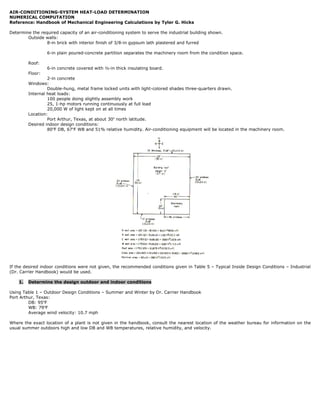
Determine the required capacity of an air-conditioning system to serve the industrial building shown.
Outside walls:
8-in brick with interior finish of 3/8-in gypsum lath plastered and furred
6-in plain poured-concrete partition separates the machinery room from the condition space.
Roof:
6-in concrete covered with ½-in thick insulating board.
Floor:
2-in concrete
Windows:
Double-hung, metal frame locked units with light-colored shades three-quarters drawn.
Internal heat loads:
100 people doing slightly assembly work
25, 1-hp motors running continuously at full load
20,000 W of light kept on at all times
Location:
Port Arthur, Texas, at about 30o north latitude.
Desired indoor design conditions:
80oF DB, 67oF WB and 51% relative humidity. Air-conditioning equipment will be located in the machinery room.
If the desired indoor conditions were not given, the recommended conditions given in Table 5 – Typical Inside Design Conditions – Industrial
(Dr. Carrier Handbook) would be used.
1. Determine the design outdoor and indoor conditions
Using Table 1 – Outdoor Design Conditions – Summer and Winter by Dr. Carrier Handbook
Port Arthur, Texas:
DB: 95oF
WB: 79oF
Average wind velocity: 10.7 mph
Where the exact location of a plant is not given in the handbook, consult the nearest location of the weather bureau for information on the
usual summer outdoors high and low DB and WB temperatures, relative humidity, and velocity.
2. 2. Compute the sunlight heat gain
The sunlight heat gain results from the solar radiation through the glass in the building’s windows and materials of construction in certain of
the building walls. If the glass or wall of a building is shaded by an adjacent solid structure, the sunlight heat gain for that glass and wall is
usually neglected. The same is true for the glass and wall of the building facing the north.
Table 15 – Solar Heat Gain thru Ordinary Glass by Dr. Carrier Handbook
Btu
Maximum radiation is 165 , occurs through east (sunrise) and west (sunset) walls at 8:00 AM for the east wall and the same
hr − ft 2
for the west wall at 4:00 PM.
sunlight heat gain = (glass area)(solar heat gain TABLE 15)(factor for shades, if any are used)
Where shades are used in the building, choose a suitable shade factor from the appropriate Guide table, (Table 16 – Over-all Factors for Solar
Heat Gain thru Glass by Dr. Carrier Handbook) and insert it in the equation above.
For metal frame locked units with light-colored shades three-quarters drawn, we use 0.60.
West-glass sunlight heat gain
Btu
west sunlight heat gain = (22 windows)(5 ft x 8 ft)165
(0.60)
hr − ft 2
Btu
west sunlight heat gain = 87120
hr
East-glass sunlight heat gain
Btu
east sunlight heat gain = (20 windows)(5 ft x 8 ft)11
(0.60)
2
hr − ft
Btu
east sunlight heat gain = 5280
hr
South-glass sunlight heat gain
Btu
south sunlight heat gain = (10 windows)(5 ft x 8 ft)13
(0.60)
hr − ft2
Btu
south sunlight heat gain = 3120
hr
North-glass sunlight heat gain
Btu
north sunlight heat gain = (15 windows)(5 ft x 8 ft)11
(0.60)
hr − ft2
Btu
north sunlight heat gain = 3960
hr
The weight per sq. ft of given material is shown in TABLE 21 to Table 33 - Transmission Coefficient U
For the walls: 8-in brick with interior finish of 3/8-in gypsum lath plastered and furred:
lb Btu
Weight: 80 2 U = 0.29
ft hr − ft 2 −o F
For the roof: 6-in concrete covered with ½-in thick insulating board:
lb Btu
Weight: 70 2 U = 0.27
ft hr − ft 2 − o F
The same three walls, and the roof, are also subject to sunlight heat gains. Table 19 and Table 20 – Equivalent Temperature Difference (Deg
F) shows the temperature difference based on the weight of wall and roof resulting from sunlight heat gains.
For west wall:
Temp. Difference: 12 oF
For east wall:
Temp. Difference: 18 oF
For south wall:
Temp. Difference: 16 oF
For north wall:
Temp. Difference: 4 oF
For the roof:
Temp. Difference: 32 oF
sunlight heat gain = (wall area)(wall transmission coefficient)(temperature difference)
3. Hence, sunlight heat gains:
For west wall:
Btu
west sunlight heat gain = (1220 ft 2 ) 0.29
o
(12 F)
hr − ft 2 − o F
Btu
west sunlight heat gain = 4245.6
hr
For east wall:
Btu
east sunlight heat gain = (1300 ft 2 ) 0.29
(18 o F)
hr − ft 2 − o F
Btu
east sunlight heat gain = 6786
hr
For south wall:
Btu
south sunlight heat gain = (1100 ft 2 ) 0.29
(16 o F)
hr − ft 2 − o F
Btu
south sunlight heat gain = 5104
hr
For north wall:
Btu o
north sunlight heat gain = (900 ft 2 ) 0.29
(4 F)
hr − ft 2 −o F
Btu
north sunlight heat gain = 1044
hr
For the roof:
Btu
roof sunlight heat gain = (21875 ft 2 ) 0.27
o
(32 F)
hr − ft 2 − o F
Btu
roof sunlight heat gain = 189000
hr
Btu
The sum of the sunlight heat gains gives the total sunlight gain, or 305659.6
hr
Use design factor of 1.5:
Btu
Sunlight heat gain = 458489.4
hr
Sunlight heat gain = 134.3152 kW
3. Compute the glass transmission heat gain
All the glass in building windows is subject to transmission of heat from outside to the inside as a result of the temperature difference
between the outdoor and indoor dry-bulb temperatures. This transmission gain is commonly called the all-glass gain.
Glass transmission heat gain
glass transmission heat gain = (total glass area)(coefficient of glass heat transmission)(outdoor DB temperature − indoor DB temperature)
Where coefficient of glass heat transmission using Table 33 – Transmission Coefficient U – Windows, skylights, doors and glass block walls by
Btu
Dr. Carrier Handbook. For single glass without storm windows: 1.13
hr − ft 2 − o F
Btu
glass transmission heat gain = (2680ft 2 )1.13
(95 − 80)o F
hr − ft2 − o F
Btu
glass transmission heat gain = 45426
hr
Wall transmission heat gain
The transmission heat gain of the south, east and west walls can be neglected because the heat gain is greater. Hence, only the north-wall
transmission heat gain needs to be computed.
wall transmission heat gain = (wall area)(coefficient of heat transmission)(outdoor DB temperature − indoor DB temperature)
For the walls: 8-in brick with interior finish of 3/8-in gypsum lath plastered and furred:
lb Btu
Weight: 80 2 U = 0.29
ft hr − ft 2 −o F
4. For west wall:
Btu
west transmission heat gain = (1220 ft 2 ) 0.29
(95 − 80)o F
hr − ft2 −o F
Btu
west transmission heat gain = 5307
hr
For east wall:
Btu
east sunlight heat gain = (1300 ft2 ) 0.29
(95 − 80)o F
hr − ft2 −o F
Btu
east transmission heat gain = 5655
hr
For south wall:
Btu
south sunlight heat gain = (1100 ft2 ) 0.29
(95 − 80)o F
hr − ft2 −o F
Btu
south transmission heat gain = 4785
hr
For north wall
Btu
north transmission heat gain = (900 ft 2 ) 0.29
(95 − 80)o F
hr − ft 2 − o F
Btu
north transmission heat gain = 3915
hr
The heat gain from the ground can be neglected because the ground is usually at a temperature than the floor. Thus the total transmission
heat gain is the sum of the individual gains.
Btu
The sum of the transmission heat gains gives the total transmission gain, or 65088
hr
Use design factor of 1.5:
Btu
Transmission heat gain = 97632
hr
Transmission heat gain = 28.6014 kW
5. 4. Compute the infiltration heat gain
The infiltration heat gain is the heat through cracks caused by the wind acting on the building.
Since the wind cannot act on all sides of the building at once, one-half the total crack length is generally used (but never less than one half)
in computing the infiltration heat gain.
Note that crack length varies with different types of windows.
inf iltration heat gain = (window crack length)(window inf iltration)(outdoor DB temperature − indoor DB temperature)(1.08)
The factor 1.08 converts the computed infiltration to Btu/h.
For general type of windows the crank length is given by:
Crack length = (3 x width) + (2 x height)
Crank length = (67 windows)(3 * 5ft) + (2 * 8ft) = 2077 ft
By using one-half of the total crank length:
2077 ft
Crank length = = 1038.5 ft
2
For the window infiltration, use Table 41 – 44 Infiltration Thru Windows and Doors by Dr. Carrier Handbook
ft 3 / min
Window infiltration for 10 mph wind velocity to a double hung window, metal sash: 0.78
crank length
Hence, the heat gain due to infiltration through the window cracks:
ft 3 / min
inf iltration heat gain = (1038.5 ft) 0.78 (95 − 80) o F(1.08)
crank length
Btu
inf iltration heat gain = 13122 .486
hr
inf iltration heat gain = 3.8504 kW
5. Compute the outside-air bypass heat load
Some outside air may be needed in the conditioned space to ventilate fumes, odors and other undesirables in the conditioned space. This
ventilation air imposes a cooling or dehumidifying load on the air conditioner because the heat or moisture, or both must be removed from
the ventilation air. Most air conditioners are arranged to permit some outside air to bypass the cooling coils. The bypassed outdoor air
becomes a load within the conditioned space similar to infiltration air.
The recommended ventilation air quantity cfm per person is from Table 45 – Ventilation Standard by Dr. Carrier Handbook
cfm
For factories the recommended cfm per person is 10
person
cfm ft 3
Since there are 100 people in this factory, the required ventilation quantity is 10
(100 person) = 1000
person min
Table 61 and 62 shows the Typical Bypass Factors for finned coils and various applications, respectively.
For factories the recommended bypass factor ranges from 0.10 to 0.20, we assume 0.10 for this installation
bypass heat load = (cfm of ventilation air)(outdoor DB temperature − indoor DB temperature)(air conditioner by pass factor)(1.08)
Hence;
ft 3
bypass heat load = 1000
(95 − 80)o F(0.10)(1.08)
min
Btu
bypass heat load = 1620
hr
bypass heat load = 0.4783 kW
6. 6. Compute the heat load from internal heat sources
Within an air-conditioned space, heat is given off by people, lights, appliances, machines, pipes, etc.
People
sensible heat load = (number of people) (sensible heat release per person)
For this building with 80oF indoor dry-bulb temperature and 100 occupants doing light work, the heat load produced is from
Btu
Table 48 – Heat Gain from People is 220 .
hr
Btu Btu
sensible heat load = (100people) 220
= 22000
hr hr
Motors
(motor − hp)(2546)
motor heat load =
motor efficiency
For 25, 1-hp motors running continuously at full load, from Table 53 – Heat Gain from Electric Motors, efficiency is 79%.
(25)(1 − hp)(2546) Btu
motor heat load = = 80569.62
0.79 hr
Light bulbs
20,000 W of light kept on at all times
Using Table 49 – Heat Gain from Lights
heat gain from lights = Total watts * 1.25 * 3.4
Btu
heat gain from lights = 20,000W * 1.25 * 3.4 = 85000
hr
Thus, the total internal heat load is:
Btu
Internal heat load = 187569.62
hr
Internal heat load = 55.38 kW
7. Compute the room sensible heat
Find the sum of the sensible heat gains computed is steps 2 (sunlight heat gain), 3 (transmission heat gain), 4 (infiltration heat gain), 5
(outside air heat gain) and 6 (internal heat sources). This sum is the room sensible-heat subtotal.
Btu
sensible-heat subtotal = (458489.4 + 97632 + 13122.486 + 1620 + 187569.62)
hr
Btu
sensible-heat subtotal = 758433.506
hr
A further sensible heat gain may result from supply-duct heat gain, supply-duct leakage loss, and air-conditioning-fan horsepower. A design
factor is usually added in the form of percentage. Using an assumed design factor of 5 percent to cover various losses that may be
encountered in the system.
Btu
sensible-heat subtotal = 796355.1813
hr
sensible-heat subtotal = 235.1144 kW
7. 8. Compute the room latent heat
The room latent load results from the moisture entering the air-conditioned space with the infiltration and bypass air, moisture given off by
room occupants, and any other moisture source such as open steam kettles, sterilizers, etc.
Infiltration Latent Heat
inf iltration latent heat load = (cfm inf iltration)(moisture content of outside air − moisture content of inside air; gr / lb)(0.68)
Using psychrometric chart or Table 41 – 44 Infiltration Thru Windows and Doors by Dr. Carrier Handbook
ft 3 / min
Window infiltration for 10 mph wind velocity to a double hung window, metal sash: 0.78 and knowing
crank length
ft 3 / min
( )
3
Crank length = 1038.5 ft , hence, cfm infiltration is 1038.5 ft 0.78 = 810.03 ft .
crank length min
Outdoor Design Conditions:
DB: 95oF and WB: 79oF
Using Table 1 – Outdoor Design Conditions – Summer and Winter by Dr. Carrier Handbook
gr
Moisture content: 124
lb
NOTE: Using Psychrometric chart, we can say that 124 gr/lb = 0.01772 lb/lb
Indoor design conditions:
80oF DB, 67oF WB and 51% RH
lb 124 gr / lb
Using psychrometric, chart moisture content: 0.01117
= 78.1648 gr
lb 0.01772 lb / lb
lb
Hence;
Ventilation Latent Heat
ventilation latent heat load = (cfm inf iltration)(moisture content of outside air − moisture content of inside air; gr / lb)(bypass factor)(0.68)
cfm ft 3
Since there are 100 people in this factory, the required ventilation quantity is 10
(100 person) = 1000
person min
Hence;
ft 3
ventilation latent heat load = 1000 (124 − 78.1648) gr ( 0.10)(0.68) = 3116.7936 Btu
min lb hr
People
people latent heat = (number of occupants)(latent heat gain)
For this building with 80oF indoor dry-bulb temperature and 100 occupants doing light work, the latent heat load produced is
Btu
from Table 48 – Heat Gain from People is 530 .
hr
Hence;
Btu Btu
people latent heat = (100) 530
= 53000
hr hr
Btu
Find the latent heat subtotal by taking the sum of the above heat gains: sensible-heat subtotal = 81363.7568
hr
Using an allowance of 5 percent for supply-duct leakage loss and safety margins:
Btu
latent-heat subtotal = 85431.9446
hr
latent-heat subtotal = 25.035 kW
8. 9. Compute the outside heat
Air brought in for space ventilation imposes a sensible and latent heat load on the air-conditioning apparatus.
Sensible Outside space ventilation:
outside ventilation = (cfm outside ventilation air)(design DB − inside DB)(1 − bypass factor)(1.08)
ft 3
outside ventilation = 1000 (95 − 80)o F(1 − 0.10)(1.08) = 14580 Btu
min hr
Latent Outside space ventilation:
outside latent heat load = (cfm out ventilation)(moisture content of outside air − moisture content of inside air; gr / lb)(1 − bypass factor)(0.68)
ft 3
outside latent heat load = 1000 (124 − 78.1648) gr (1 − 0.10)(0.68) = 28051.1424 Btu
min lb hr
10. Compute the grand-total heat and refrigeration tonnage
Room total heat load = room sensible heat + room latent heat
Btu Btu
Room total heat load = [796355.1813 + 14580] + [85431.9446 + 28051.1424]
hr hr
Btu
Room total heat load = 924418.2683
hr
Room total heat load = 271.1252 kW
Refrigeration Load, tons
room total heat load, Btu / hr
Refrigeration load =
12000, Btu / hr per ton
924418.2683Btu / hr
Refrigeration load =
12000, Btu / hr per ton
Refrigeration load = 77 tons
Quantity of cooling water required
The quantity of cooling water required for the refrigeration-system condenser is Q.
tons of refrigeration
Q = 30
condenser water temperature rise, o F ; gpm
Assuming at 75oF entering water temperature and 95oF leaving water temperature.
77 tons
Q = 30
95 o F − 75 o F
Q = 115.5 gpm
11. Compute the sensible heat factor and apparatus dew point
Sensible heat factor (SHF)
room sensible heat
sensible heat factor =
room total heat
Btu
796355.1813
sensible heat factor = hr
[796355.1813 + 14580] Btu
hr
sensible heat factor = 0.9820
Apparatus dew point temperature:
Using psychrometric chart and known room conditions, we find apparatus dew point temperature.
Apparatus dew point temperature = 60oF or 15.76oC
9. 12. Compute the quantity of dehumidified air required
dehumified air temperature rise = (1 − bypass factor)(indoor temperature − apparatus dew po int)
dehumified air temperature rise = (1 − 0.10)(80 o F − 60 o F)
dehumified air temperature rise = 18oF
room sensible heat
dehumified air quantity =
(
1.08 dehumified air temperature rise ) ; cfm
Btu
796355.1813
dehumified air quantity = hr
1.08 (18 o F)
dehumified air quantity = 40964.7727 cfm