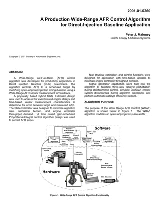
2. calculation using feedback from a Wide-Range AFR
sensor located close to the engine upstream of a warm-
up catalyst for fast AFR control capability. The WRAF Test Configuration
algorithm and feedback loop is shown with dark lines in
Figure 1. MY 1998 Mitsubishi Carisma, 3250 Lb I.W.C
A stoichiometric switching AFR sensor was placed 1.8L DI-Gas Engine
downstream of the NOx adsorber to be used in
conjunction with a Post Adsorber Oxygen Sensor Manual Transmission
Feedback Algorithm to correct the front WRAF sensor
voltage with an offset. Long-term pulsewidth multiplier Delphi 32-Bit Engine Controller with Torque-Structure
corrections are stored in Powertrain Control Module and WRAF software
(PCM) memory by an Adaptive AFR Feedback
algorithm.
Delphi 50 CUL Warmup Converter and 120 CUL NOx
Adsorber. 40 hrs fuel cut-off aging, Adsorber bed temp
The following design features were included in the
850 deg C
WRAF algorithm:
Delphi Electronic Throttle and EGR Actuators
• Generality for both Port Fuel Injected (PFI) and Gas-
DI applications
ETAS Wide-Range AFR Sensor AWS/LSU-4. 11 to 50
AFR measurement range.
• Explicit accounting for event-based delays from the
point of injection to the measurement location
Cold MVEG B emission cycle (1180 sec)
• Explicit accounting for variation of WRAF sensor
Test Fuel: Similar to California Phase II:
dynamics with operating conditions
Low Sulfur, 15 ppm by mass
H/C Ratio 1.797, O/C Ratio 0.015, Stoich. 14.16
• AFR error signal availability in both open and Emission Standard:
closed-loop operation 0.1 g/km HC, 1.0 g/km CO, 0.08 g/km NOx
Emission Results:
• Closed-loop operation under rich AFR conditions at 0.1 g/km HC, 0.4 g/km CO, 0.035 g/km NOx
high engine loads Table 1. Gas-DI Euro IV Test Configuration
• Catalyst perturbation under stoichiometric operating
conditions with directly adjustable frequency and Figure 2 below shows an example of WRAF control
amplitude capability at a 2000 RPM, 30 Kpa intake manifold
pressure, 3% throttle position operating point.
• Sequential calibration steps with built-in calibration
aids such as external disturbance, command input,
and catalyst efficiency sweeps
Maintaining fast, accurate AFR control in the
exhaust stream is important in Gasoline Direct Injection
(Gas-DI) engine applications because of the sensitivity
of NOx emissions to AFR errors under homogeneous
stoichiometric and homogeneous lean combustion
conditions.
RESULTS SUMMARY
The WRAF algorithm was used on a 1998 Mitsubishi
Gas-DI vehicle development platform to meet the Euro
AF
IV emissions standard. The vehicle was equipped with a
Delphi Engine Management System, including engine
controller and software, warm-up catalyst, and NOx
adsorber. A summary of the test configuration and test
results data are shown below in Table 1.
Figure 2. Example of WRAF Control Capability
3. The bottom portion of Figure 2 shows the capability of solely a function of the time between engine fueling
the WRAF algorithm to follow an arbitrary AFR events (e.g. 4 events per engine cycle on a 4 cylinder
command input signal, composed of a sine-wave and engine application).
square wave combination. The high amplitude signal in
Figure 2 is the command AFR input, and the two low The lag dynamics of the WRAF sensor were modeled in
amplitude delayed AFR signals are estimated and the AFR Control Error Estimator to provide a good
measured AFR respectively. The estimated and comparison basis between model and measurement in
measured signals are not the true AFR at the sensor constructing a Control Error Estimate. The model of
location because both signals account for the effects of sensor lag dynamics was designed to emulate analog
sensor attenuation on the measurement. sensor subsystem behavior by using time-based
calculation updates. Figure 5 shows the functionality
ALGORITHM DESIGN contained within the AFR Control Error Estimator Block
of Figure 3. In the Control Error Estimator, the perturbed
The functionality contained within the WRAF control AFR command input is delayed and attenuated by the
algorithm block of Figure 1 is shown below in Figure 3. Engine Transport Delay and WRAF Sensor Lag Model
The WRAF algorithm is composed of three main sub- blocks respectively.
blocks allocated to error estimation, control, and AFR
perturbation for catalyst efficiency optimization. The Engine Transport Delay block is composed of an
array of memory buffers, which store the 25 of the
ESTIMATOR DESIGN previous AFR commands on an event basis. A
calibration is used to determine which memory buffer to
The AFR Control Error Estimator block in Figure 3 is read as a function of engine operating conditions, so as
responsible for producing a leading estimate of fuel to synchronize the delayed, commanded AFR with the
control errors by comparing an open-loop commanded sensor measurement location.
AFR signal to a measured pre-catalyst Wide-Range AFR
sensor measurement. The estimated control error is a The WRAF Sensor Lag Model block contains a digital
dimensionless percentage value referenced to the open- first-order low-pass filter. The filter time-constant
loop commanded AFR. The open-loop commanded characteristic is varied by means of a calibration that
AFR signal is received from the open-loop fuel algorithm changes with engine operating conditions to reflect
block of Figure 1 as a first estimate of the expected AFR changes in sensor dynamics.
in the exhaust system.
The perturbed, delayed, attenuated command AFR is
To calculate the correct fueling error, the estimator must then compared to measured AFR from the WRAF
account for the physical effects of transport delay across sensor by the Disturbance Estimator PI block to produce
the engine and the effects of WRAF sensor lag a leading estimate of the AFR control error. The
dynamics as discussed in [1][2], and shown conceptually Disturbance Estimator PI block uses
in Figure 4. Proportional/Integral feedback with fixed gains to reduce
the error between the modeled AFR and the measured
An injected air-fuel mixture must travel from the point of AFR to zero.
injection to the point of measurement. The travel time
(pure delay) across the engine from the injection point to The AFR measurement is constructed in the AFR
the close-mounted WRAF sensor was assumed to be
AFR
Perturbation
Generator
(Time)
+
+
Open-Loop AFR (Time)
AFR
Control Gain-Scheduled
Error PI Control X
Front Wide-Range AFR Estimator ControlError (Time) Closed-Loop
Sensor Voltage (Event) (Hybrid) Estimate Multiplier (Time)
Front AFR Sensor Offset Voltage (Time)
Figure 3. Functionality of the Wide-Range AFR Control Block
4. Figure 4. Physical Effects of Engine and Sensor on AFR
Front AFR Sensor Offset Voltage (Time)
+
WRAF Sensor
Calibration
Front Wide-Range AFR + (Event)
Sensor Voltage (Event)
Open Loop Perturbated AFR (Time)
Engine + WRAF -
TransportDelay Sensor +
Model LagModel
(Event)
- (Time)
Disturbance
Estimator
PI
(Time)
AFR Integral Error
Delayed AFR Command Control Error Estimate (Time)
Figure 5. Hybrid AFR Control Error Estimator Design
5. Control Error Estimator block by measuring the pre- used for smooth control.
catalyst WRAF sensor voltage, correcting the voltage
measurement with voltage offset feedback from the post- The control integrator is limited to prevent wind-up and
NOx adsorber switching oxygen sensor, and calculating increase vehicle robustness to WRAF sensor failures
the measured AFR using a stored sensor calibration between occurrence and detection. Reset features were
lookup table. added to the integrator and closed-loop correction for
vehicle conditions such as fuel cut-off, stratified
The Disturbance Estimator PI block is based on the operation (fuel lead), and WRAF sensor warm-up
analytical disturbance rejection control theory in [3], in conditions.
which the integral portion of the PI feedback is used to
provide a leading estimate of the control error between AFR PERTURBATION GENERATOR DESIGN
model and estimate. Since the activity of determining
control error is an artificial process, a time-based update The AFR Perturbation Generator shown in Figure 3 is
was used for the Disturbance Estimator PI block to responsible for adding a variable frequency, variable
minimize engine controller throughput demand. amplitude square-wave offset to the commanded open-
loop AFR for catalyst efficiency optimization and
The AFR Control Error Estimator block shown in Figures calibration activity support. Catalyst AFR perturbation
3 and 5 is a hybrid system because it contains both around the stoichiometric AFR is known to enhance
engine event and time-based algorithm updates three-way catalyst efficiency relative to static AFR
necessary to accurately reflect the hybrid attributes of conditions [4].
the engine and sensor hardware.
The AFR Perturbation Generator block contains square-
CONTROLLER DESIGN wave frequency and amplitude schedule tables that are
optimized during vehicle development for maximum
Figure 3 shows the Gain-Scheduled PI Control block, catalyst efficiency trade-offs. The output of the
which is responsible for producing a closed-loop generator is supplied to the AFR Control Error Estimator
correction multiplier to the injector pulse-width, to correct so that the perturbations are accounted for in the error
fueling errors found by the AFR Control Error Estimator calculations. The injector pulse-width is modified directly
Block. by the perturbation block to deliver the desired AFR
perturbations to the engine and exhaust system.
Figure 6 shows the functionality contained within the
Gain-Scheduled PI Control block of Figure 3. During calibration development of the WRAF algorithm,
it is desirable to tune the PI gains of both the Control
Error Estimator and Gain-Scheduled PI Control blocks
by simulating unknown disturbances with fuel injector
1 pulsewidth.
+
P.Gain
(Time)
- The switch symbol shown in Figure 3 represents a
-
Closed-Loop Correction (Time)
calibration variable used to de-couple the perturbation
AFR signal from the Control Error Estimator while
retaining injector pulsewidth perturbations. The switch
Control Error Estimate (Time)
can be used to tune the responsiveness of the Control
EventPeriod
Integral Limited Integrator
Error Estimate to unknown disturbances with the Error
Event Period (Time)
Gain
Schedule
X (Time)
Estimator PI gains.
(Time)
Error
Integral
After the Control Error Estimator is tuned, the Gain-
Control Error Estimate (Time)
Gain
Schedule
Scheduled PI Control block gains are tuned for
(Time)
disturbance rejection performance.
Figure 6. Gain-Scheduled PI Controller Design
The perturbation generator can also be used to produce
a fixed-frequency, variable amplitude signal for catalyst
The Gain-Scheduled PI Controller uses a limited gain-
scheduled integrator on the Control Error Estimate to
SUMMARY
correct fueling errors. Two gain-schedule calibrations
were used for the control integrator.
A production Wide-Range Air-Fuel-Ratio (AFR) control
algorithm was developed for production application in
Integral gain is decreased for long engine event periods
Direct Injection Gasoline (DI-G) powertrains. A hybrid
(low RPM) because the time-based control algorithm can
State Estimator and time-based Controller design was
update faster than new event-based sensor information
used to accurately account for physical engine effects,
is received. Integral gain is also changed as a function
minimize calibration burden, and minimize engine
of the size of the Control Error Estimate, so that as the
controller throughput burden.
error approaches zero, lighter control feedback can be
6. ACKNOWLEDGEMENTS
Special thanks to Derk Geurts, Michel Peters, and
Bart Schreurs of the Delphi Luxembourg Technical
Centre for valuable design feedback in the initial phases
of the project.
REFERENCES
1. Fekete, N.P., “Model-Based Air-Fuel Ratio Control of a
Multi-cylinder Leanburn Engine," Stanford University PhD.
Dissertation, January 1995.
2. Vigild, C. and Hendricks, E., “A Lambda Control Observer
With Fault Correction,” IFAC Advances in Automotive
Control Workshop, 1998.
3. Franklin, G.F. et. al., "Digital Control of Dynamic Systems,"
2nd ed., Addison-Wesley Publishing Company, 1990.
4. Heywood, J. B., “Internal Combustion Engine
Fundamentals,” McGraw-Hill, 1988.