
Recommended
Recommended
More Related Content
What's hot
What's hot (20)
Similar to Progressive collapse analysis in rc structure due to 150513181706
Similar to Progressive collapse analysis in rc structure due to 150513181706 (20)
Recently uploaded
Recently uploaded (20)
Progressive collapse analysis in rc structure due to 150513181706
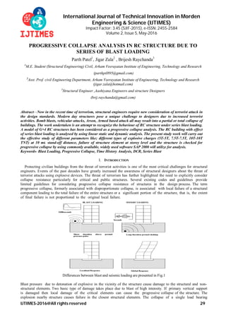
- 1. International Journal of Technical Innovation in Morden Engineering & Science (IJTIMES) Impact Factor: 3.45 (SJIF-2015), e-ISSN: 2455-2584 Volume 2, Issue 5, May-2016 IJTIMES-2016@All rights reserved 29 PROGRESSIVE COLLAPSE ANALYSIS IN RC STRUCTURE DUE TO SERIES OF BLAST LOADING Parth Patel1 , Jigar Zala2 , Brijesh Raychanda3 1 M.E. Student (Structural Engineering) Civil, Arham Veerayatan Institute of Engineering, Technology and Research (parthptl895@gmail.com) 2 Asst. Prof. civil Engineering Department, Arham Veerayatan Institute of Engineering, Technology and Research (jigar.zala@hotmail.com) 3 Structural Engineer ,Aashiyana Engineers and structure Designers (brij.raychanda@gmail.com) Abstract—Now in the recent time of terrorism, structural engineers require new consideration of terrorist attack in the design standards. Modern day structures pose a unique challenge to designers due to increased terrorist activities. Bomb blasts, vehicular attacks, Arson, Armed based attack all may result into a partial or total collapse of buildings. The work undertaken is an attempt to recognize the behaviour of RC structure under series blast loading. A model of G+4 RC structures has been considered as a progressive collapse analysis. The RC building with effect of series blast loading is analysed by using linear static and dynamic analysis. The present study work will carry out the effective study of different parameters like; different types of explosive charges (5T-5T, 7.5T-7.5T, 10T-10T TNT) at 10 mt. stand-off distance, failure of structure element at storey level and the structure is checked for progressive collapse by using commonly available, widely used software SAP 2000 will utilize for analysis. Keywords- Blast Loading, Progressive Collapse, Time History Analysis, DCR, Series Blast I. INTRODUCTION Protecting civilian buildings from the threat of terrorist activities is one of the most critical challenges for structural engineers. Events of the past decades have greatly increased the awareness of structural designers about the threat of terrorist attacks using explosive devices. The threat of terrorism has further highlighted the need to explicitly consider collapse resistance particularly for critical and public structures. Several existing codes and guidelines provide limited guidelines for considering progressive collapse resistance of structures in the design process. The term progressive collapse, formerly associated with disproportionate collapse, is associated with local failure of a structural component leading to the total failure of the entire structure or a significant portion of the structure, that is, the extent of final failure is not proportional to the original local failure. Differences between blast and seismic loading are presented in Fig.1 Blast pressure due to detonation of explosive in the vicinity of the structure cause damage to the structural and non- structural elements. Two basic type of damage takes place due to blast of high intensity. If primary vertical support is damaged then local damage of the critical elements can cause the progressive collapse of the structure. The explosion nearby structure causes failure in the closest structural elements. The collapse of a single load bearing
- 2. International Journal of Technical Innovation in Morden Engineering & Science (IJTIMES) Volume 2, Issue 4, April-2016, e-ISSN: 2455-2584,Impact Factor: 3.45 (SJIF-2015) IJTIMES-2015@All rights reserved 30 structural element or few structural elements may lead to progressive collapse of a part or the whole building which is referred as Global damage. Figure - 1.2 Column damage due to direct blast loading II. ANALYSIS PROCEDURE 2.1 Progressive collapse is a well-understood physical occurrence. However, its mathematical representation still requires clarifications explanations and improvements. Progressive collapse analysis is performed by instant loss of one or several primary load-bearing elements and analysing structure’s remaining capability to absorb this local damage. There are four methods for analysis of progressive collapse in buildings: 1. Linear static method (LSM). 2. Non-Linear static method (NLSM). 3. Linear Dynamic method (LDM). 4. Non-Linear Dynamic method (NLDM). The key issue in understanding the “progressive collapse” is that it is a dynamic event and the motion is initiated by a release of internal energy due to instantaneous loss of a structural component. This member loss disturbs the initial load equilibrium of external loads & internal forces & the structure than vibrates until a new equilibrium position is found or until the structure collapses. 2.2 STEPS FOR PROGRESSIVE COLLAPSE ANALYSIS: 1. Determine DL, LL and EQ load and design the structure for them. 2. Calculation of blast load for various columns of the structure, and apply it on the structure. 3. Checking the adequacy of the frame members through the Demand Capacity Ratio of branding moments. 4. Check if any key carrying element is fails if it is fail then remove it. 5. Re-analysis of the structure for gravity Analysis after removing the frame members in which demand exceeds Capacity. 6. Checking for progressive collapse, if any, in the structure. 2.3 Acceptance criterion for progressive collapse: The GSA 2003 proposed the use of the Demand–Capacity Ratio (DCR), the ratio of the member force and the member strength, as a criterion to determine the failure of main structural members by the linear analysis procedure. DCR = Q/ QCE where QUD is the acting force (demand) determined in component (moment, axial force, and shear etc.); and QCE is the expected ultimate, unfactored capacity of the component (moment, axial force, shear etc.).; In the GSA 2003 the inherent strength is obtained by multiplying the nominal strength with the over strength factor of 1.1, and the strength reduction factor is not applied. The acceptance criteria for DCR vary from 1.25 to 3.0 depending on the width/thickness ratio of the member. The adequacy of columns has been checked according to Clause 39.6 of IS 456:2000. III CONFIGURATION AND ANALYTICAL MODELING OF MODEL STRUCTURE 3.1DESCRIPTION OF THE CASE STUDY: The structure which is taken as case study has following features: Storey : G+4 Storey building Usage : Administrative Structure Location : Delhi Structural System : Moment Resisting frame Area : 30m X 20m Total Height of Building : 20m
- 3. International Journal of Technical Innovation in Morden Engineering & Science (IJTIMES) Volume 2, Issue 4, April-2016, e-ISSN: 2455-2584,Impact Factor: 3.45 (SJIF-2015) IJTIMES-2015@All rights reserved 31 Typical Bay width : 5 m width in x-direction 5m width in z-direction Typical storey height : 4m Beam size : 230 mm X 600 mm Column size : 450 mm x 450 mm This structure which is taken for case study is only one portion of the total structure as to understand the behaviour of the structure under conventional loads (As per IS: 875-1987 Part-I and Part-II) and under blast load. Live Load : 3 KN/m2 Floor Finish : 1.25KN/m2 Wall load : 4.6 KN/m Slab Load : 3.75 KN/m2 Seismic zone, Z : 0.24 (Zone-IV) Importance Factor, I : 1 Response Reduction Factor, R : 5 (SMRF) Type of soil : Medium Height of structure, h : 20m Fck (concrete) : M25 Fy (steel) : 415 3.2ASSUMPTION MADE FOR THE ANALYSIS PROCEDURE: Following assumptions are made during the analysis of the structure, 1. Blast load is applied on the ground floor columns. 2. Bollards are considered at 10m distance from the structure. Hence stand-off distance is considered as 10m. 3. Impact Load of the floors collapsing due to blast on the floors below is not considered. 4. Effect of increased strength due to high strain rate is not taken into account. 5. Effect of temperature stress is not considered. Load Combinations are considered as per IS: 1893-2002 which are as follows: 1. DL+LL 2. 1.5 (DL+LL) 3. 1.5 (DL±EQx) and 1.5 (DL±EQz) 4. 0.9DL ± 1.5 EQx and 0.9DL ± 1.5Eqz Dynamic pressure of Blast is calculated as below (Biggs), Scaled Distance and Scaled time is found out by below equations. As after finding out blast load there are two more load combination are added: 5. DL+BLAST 6. DL +BLAST+LL
- 4. International Journal of Technical Innovation in Morden Engineering & Science (IJTIMES) Volume 2, Issue 4, April-2016, e-ISSN: 2455-2584,Impact Factor: 3.45 (SJIF-2015) IJTIMES-2015@All rights reserved 32 Figure – 3.1 Blast at column A-3 & A-5 Figure – 3.2 Typical Floor Plan Layout As in Blast, Size of Explosive, Location of Blast and Distance of Blast from the structure plays important factor. Hence, Location of Blast is considered at ground level near A-3 & A-5 column (See Fig. 3.1), Dotted line in the periphery of the structure shows the bollards which are considered at 10m distance from structure as specified before and Structure was checked for various sizes of explosives like 5-5, 7.5-7.5&10-10Tonne. Figure – 3.3 3D Model in Software
- 5. International Journal of Technical Innovation in Morden Engineering & Science (IJTIMES) Volume 2, Issue 4, April-2016, e-ISSN: 2455-2584,Impact Factor: 3.45 (SJIF-2015) IJTIMES-2015@All rights reserved 33 IV ANALYSIS AND RESULTS The SAP 2000 model is shown in the figure 3.3. Blast load depends on time as it decreases with time. Hence it is defined as time history function in model and applied to the structure. Generally, the structure is analysed for conventional loading. Hence results of that model are compared with blast load model results to find out the key load carrying elements in which deficiency occurs due to blast. As the structure is analysed for different sizes of high explosives like 5-5T, 7.5-7.5T&10-10T, from10m stand-off distance .Hence effect on the structure is different. Due to 7.5-7.5T blast from 10m stand-off distance, six columns are failing and progressive collapse happens. DCR check graphs for 7.5-7.5T & 10-10T are shown in fig. 4.1 & 4.2. Graph – 4.1 DCR check for 7.5-7.5T Graph – 4.2 DCR check for 10-10T
- 6. International Journal of Technical Innovation in Morden Engineering & Science (IJTIMES) Volume 2, Issue 4, April-2016, e-ISSN: 2455-2584,Impact Factor: 3.45 (SJIF-2015) IJTIMES-2015@All rights reserved 34 After finding out key load carrying elements, key elements are removed and structure is analysed for the progressive collapse and DCR check is done. Another model is made and members which are failing in DCR check in 1st stage of progressive collapse are removed from that model and procedure is repeated. Hence, the procedure is repeated till all the member passes in DCR check i.e. progressive collapse stops and snaps of the each stage of progressive collapse are shown (See Fig. 4.1 to 4.3) Figure – 4.1 Figure – 4.2 Figure – 4.3 Progressive Collapse 1st Stage Progressive Collapse 2nd Stage Progressive Collapse 2nd Stage (Key Elements removed) (back side view) (back side view) IV.CONCLUSIONS Building is analyzed for different sizes of high explosives like 5-5T, 7.5-7.5T&10-10T, from different stand-off distance like 10m. In case of 5-5T charge weight, Blast load is not governing load. In case of 10-10TExplosive charge weight from 10m stand-off distance, most of the columns are failing. Hence there is no space for Progressive Collapse. In case of 7.5-7.5T Explosive charge weight, from 10m stand-off distance, 6 columns are failing. After removing those six columns, Progressive Collapse analysis is done in which whole building collapses in 4th stage of Progressive Collapse. It would be perfectly in right order to say that the charge weight to stability of a building is directly dependent on the quantity of explosives used in terrorist attack. Performance level of building of building is reached to collapse point for minimum stand-off distance. For important structures, blast analysis needs to carry out by keeping in view the terrorist activities in today’s scenario. For the high-risk facilities such as public and commercial buildings, design considerations against extreme events are very important. References [1] H. S. Lew, “Analysis Procedures for Progressive Collapse of Buildings”, Building & Fire research laboratory, NIST, 2005. [2] Nicholas J. Carino H.S. Lew “Summary of NIST/GSA Workshop on Application of Seismic Rehabilitation Technologies to Mitigate Blast-Induced Progressive Collapse” September 10, 2001. [3] Bangash, M.Y.H and Bangash, T., Explosion resistant buildings, springer Berlin Heidelberg New York, 2006. [4] R. Shankar Nair, P.E., “Progressive collapse basics,” The Steel Conference, March 2004, pp. 1-3. [5] 20. S. M. Marjanishvili, “Progressive Analysis Procedure for Progressive Collapse” Journal of performance of constructed facilities, ASCE, Vol. 18,No. 2, May 1, 2004, pp. 79-85. [6] Progressive Collapse – Historical Perspactive, Brian Crowder, NAVFAC, 2005 [7] P. Mendis, A. Gupta & J. Ramsay, “Blast Loading and Blast Effect on Structures – An Overview”, eJSE, 2007. [8] T. Ngo, P. Mendis, A. Gupta & J. Ramsay., “Blast Loading and Blast Effects on Structures – An Overview”, Electronic Journal of Structural Engineering Special Issue: Loading on Structures, 2007, pp. 76-91. [9] Paul F Mlakar Sr.,W Gene Corley., “The oklahoma city bombing Analysis of blast damage to the murrah building”, Journal of performance of constructed facilities ASCE, Vol. 12. No.3. August. 1998, pp. 113-119.
- 7. International Journal of Technical Innovation in Morden Engineering & Science (IJTIMES) Volume 2, Issue 4, April-2016, e-ISSN: 2455-2584,Impact Factor: 3.45 (SJIF-2015) IJTIMES-2015@All rights reserved 35 [10] Shalva Marjanishvili and Elizabeth Agnew, “Comparison of various procedures for progressive collapse analysis”, journal of performance of constructed facilities ASCE, Vol. 20, No. 4, November, 2006, pp.365-374. [11] Kapil khandelwala and sherrif EI-Tawila. “Progressive collapse analysis of seismically designed steel braced frames”, journal of Construction steel Research, Vol. 65, 2009, pp. 699-708. [12] Lt. Col. Jasinder Singh Sodhi, “Review of guidelines for blast resistant building and a case study of library building at IITK”, M.Tech Thesis, Department of Civil Engineering, Indian Institute of technology,Kanpur. [13] Charles H. Norris et al., “Structural Design for Dynamic Loads,” McGRAW-HILL Books Company, INC., 1959. [14] IITK-GSDMA Guidelines on measures to mitigate effects of terrorist attacks on buildings, May 2006, Prepared by C.V.R. Murty, Indian Institute of technology, Kanpur. [15] General Service Administration (GSA), (2003): “Progressive Collapse Analysis and Design Guidelines for New Federal Office Buildings and Major Modernization Projects.” June. [16] IS: 4991 – 1968 Criteria for blast resistant design of structures for explosions above ground. [17] Rutwik Dave, “The study of progressive collapse of the building frames subjected to blast”, Thesis for degree of M.E. (CASAD), Applied mechanics department, L.D.College of engineering, Ahmedabad.