Ss7
- 1. Signaling System 7 (SS7)
Definition
Signaling System 7 (SS7) is an architecture for performing out-of-band signaling
in support of the call-establishment, billing, routing, and information-exchange
functions of the public switched telephone network (PSTN). It identifies
functions to be performed by a signaling-system network and a protocol to enable
their performance.
Topics
1. What Is Signaling?
2. What Is Out-of-Band Signaling?
3. Signaling Network Architechture
4. The North American Signaling Architecture
5. Basic Signaling Architecture
6. SS7 Link Types
7. Basic Call Setup Example
8. Database Query Example
9. Layers of the SS7 Protocol
10. What Goes Over the Signaling Link
11. Addressing in the SS7 Network
12. Signal Unit Structure
13. What Are the Functions of the Different Signaling Units?
14. Message Signal Unit Structure
Self-Test
Correct Answers
Glossary
Web ProForum Tutorials Copyright © 1/29
http://www.iec.org The International Engineering Consortium
- 2. 1. What Is Signaling?
Signaling refers to the exchange of information between call components
required to provide and maintain service.
As users of the PSTN, we exchange signaling with network elements all the time.
Examples of signaling between a telephone user and the telephone network
include: dialing digits, providing dial tone, accessing a voice mailbox, sending a
call-waiting tone, dialing *66 (to retry a busy number), etc.
SS7 is a means by which elements of the telephone network exchange
information. Information is conveyed in the form of messages. SS7 messages can
convey information such as:
• I’m forwarding to you a call placed from 212-555-1234 to 718-555-
5678. Look for it on trunk 067.
• Someone just dialed 800-555-1212. Where do I route the call?
• The called subscriber for the call on trunk 11 is busy. Release the call
and play a busy tone.
• The route to XXX is congested. Please don’t send any messages to XXX
unless they are of priority 2 or higher.
• I’m taking trunk 143 out of service for maintenance.
SS7 is characterized by high-speed packet data and out-of-band signaling.
2. What Is Out-of-Band Signaling?
Out-of-band signaling is signaling that does not take place over the same path as
the conversation.
We are used to thinking of signaling as being in-band. We hear dial tone, dial
digits, and hear ringing over the same channel on the same pair of wires. When
the call completes, we talk over the same path that was used for the signaling.
Traditional telephony used to work in this way as well. The signals to set up a call
between one switch and another always took place over the same trunk that
would eventually carry the call. Signaling took the form of a series of
multifrequency (MF) tones, much like touch tone dialing between switches.
Out-of-band signaling establishes a separate digital channel for the exchange of
signaling information. This channel is called a signaling link. Signaling links are
used to carry all the necessary signaling messages between nodes. Thus, when a
Web ProForum Tutorials Copyright © 2/29
http://www.iec.org The International Engineering Consortium
- 3. call is placed, the dialed digits, trunk selected, and other pertinent information
are sent between switches using their signaling links, rather than the trunks
which will ultimately carry the conversation. Today, signaling links carry
information at a rate of 56 or 64 kbps. It is interesting to note that while SS7 is
used only for signaling between network elements, the ISDN D channel extends
the concept of out-of-band signaling to the interface between the subscriber and
the switch. With ISDN service, signaling that must be conveyed between the user
station and the local switch is carried on a separate digital channel called the D
channel. The voice or data which comprise the call is carried on one or more B
channels.
Why Out-of-Band Signaling?
Out-of-band signaling has several advantages that make it more desirable than
traditional in-band signaling.
• It allows for the transport of more data at higher speeds (56 kbps can
carry data much faster than MF outpulsing).
• It allows for signaling at any time in the entire duration of the call, not
only at the beginning.
• It enables signaling to network elements to which there is no direct
trunk connection.
3. Signaling Network Architecture
If signaling is to be carried on a different path from the voice and data traffic it
supports, then what should that path look like? The simplest design would be to
allocate one of the paths between each interconnected pair of switches as the
signaling link. Subject to capacity constraints, all signaling traffic between the
two switches could traverse this link. This type of signaling is known as
associated signaling, and is shown below in Figure 1.
Figure 1. Associated Signaling
Associated signaling works well as long as a switch’s only signaling requirements
are between itself and other switches to which it has trunks. If call setup and
Web ProForum Tutorials Copyright © 3/29
http://www.iec.org The International Engineering Consortium
- 4. management was the only application of SS7, associated signaling would meet
that need simply and efficiently. In fact, much of the out-of-band signaling
deployed in Europe today uses associated mode.
The North American implementers of SS7, however, wanted to design a signaling
network that would enable any node to exchange signaling with any other
SS7−capable node. Clearly, associated signaling becomes much more complicated
when it is used to exchange signaling between nodes which do not have a direct
connection. From this need, the North American SS7 architecture was born.
4. The North American Signaling
Architecture
The North American signaling architecture defines a completely new and
separate signaling network. The network is built out of the following three
essential components, interconnected by signaling link:
• signal switching points (SSPs)—SSPs are telephone switches (end
offices or tandems) equipped with SS7−capable software and
terminating signaling links. They generally originate, terminate, or
switch calls.
• signal transfer points (STPs)—STPs are the packet switches of the
SS7 network. They receive and route incoming signaling messages
towards the proper destination. They also perform specialized routing
functions.
• signal control points (SCPs)—SCPs are databases that provide
information necessary for advanced call-processing capabilities.
Once deployed, the availability of SS7 network is critical to call processing. Unless
SSPs can exchange signaling, they cannot complete any interswitch calls. For this
reason, the SS7 network is built using a highly redundant architecture. Each
individual element also must meet exacting requirements for availability. Finally,
protocol has been defined between interconnected elements to facilitate the
routing of signaling traffic around any difficulties that may arise in the signaling
network.
To enable signaling network architectures to be easily communicated and
understood, a standard set of symbols was adopted for depicting SS7 networks.
Figure 2 shows the symbols that are used to depict these three key elements of
any SS7 network.
Web ProForum Tutorials Copyright © 4/29
http://www.iec.org The International Engineering Consortium
- 5. Figure 2. Signaling Network Elements
STPs and SCPs are customarily deployed in pairs. While elements of a pair are
not generally co-located, they work redundantly to perform the same logical
function. When drawing complex network diagrams, these pairs may be depicted
as a single element for simplicity, as shown in Figure 3.
Figure 3. STP and SCP Pairs
5. Basic Signaling Architecture
Figure 4 shows a small example of how the basic elements of an SS7 network are
deployed to form two interconnected networks.
Figure 4. Sample Network
The following points should be noted:
1. STPs W and X perform identical functions. They are redundant.
Together, they are referred to as a mated pair of STPs. Similarly, STPs
Y and Z form a mated pair.
Web ProForum Tutorials Copyright © 5/29
http://www.iec.org The International Engineering Consortium
- 6. 2. Each SSP has two links (or sets of links), one to each STP of a mated
pair. All SS7 signaling to the rest of the world is sent out over these
links. Because the STPs of a mated pair are redundant, messages sent
over either link (to either STP) will be treated equivalently.
3. The STPs of a mated pair are joined by a link (or set of links).
4. Two mated pairs of STPs are interconnected by four links (or sets of
links). These links are referred to as a quad.
5. SCPs are usually (though not always) deployed in pairs. As with STPs,
the SCPs of a pair are intended to function identically. Pairs of SCPs are
also referred to as mated pairs of SCPs. Note that they are not directly
joined by a pair of links.
6. Signaling architectures such as this, which provide indirect signaling
paths between network elements, are referred to as providing quasi-
associated signaling.
6. SS7 Link Types
SS7 signaling links are characterized according to their use in the signaling
network. Virtually all links are identical in that they are 56−kbps or 64−kbps
bidirectional data links that support the same lower layers of the protocol; what is
different is their use within a signaling network. The defined link types are shown
in Figure 5 and defined as follows:
Figure 5. Link Types
Web ProForum Tutorials Copyright © 6/29
http://www.iec.org The International Engineering Consortium
- 7. A Links
A links interconnect an STP and either an SSP or an SCP, which are collectively
referred to as signaling end points ("A" stands for access). A links are used for the
sole purpose of delivering signaling to or from the signaling end points (they
could just as well be referred to as signaling beginning points). Examples of A
links are 2−8, 3−7, and 5−12 in Figure 5.
Signaling that an SSP or SCP wishes to send to any other node is sent on either of
its A links to its home STP, which, in turn, processes or routes the messages.
Similarly, messages intended for an SSP or SCP will be routed to one of its home
STPs, which will forward them to the addressed node over its A links.
C Links
C links are links that interconnect mated STPs. As will be seen later, they are used
to enhance the reliability of the signaling network in instances where one or
several links are unavailable. "C" stands for cross (7−8, 9−10, and 11−12 are C
links). B links, D links, and B/D links interconnecting two mated pairs of STPs
are referred to as either B links, D links, or B/D links. Regardless of their name,
their function is to carry signaling messages beyond their initial point of entry to
the signaling network towards their destination. The "B" stands for bridge and
describes the quad of links interconnecting peer pairs of STPs. The "D" denotes
diagonal and describes the quad of links interconnecting mated pairs of STPs at
different hierarchical levels. Because there is no clear hierarchy associated with a
connection between networks, interconnecting links are referred to as either B,
D, or B/D links (7−11 and 7−12 are examples of B links; 8−9 and 7−10 are
examples of D links; 10−13 and 9−14 are examples of interconnecting links and
can be referred to as B, D, or B/D links).
E Links
While an SSP is connected to its home STP pair by a set of A links, enhanced
reliability can be provided by deploying an additional set of links to a second STP
pair. These links, called E (extended) links provide backup connectivity to the SS7
network in the event that the home STPs cannot be reached via the A links. While
all SS7 networks include A, B/D, and C links, E links may or may not be deployed
at the discretion of the network provider. The decision of whether or not to
deploy E links can be made by comparing the cost of deployment with the
improvement in reliability. (1−11 and 1−12 are E links.)
Web ProForum Tutorials Copyright © 7/29
http://www.iec.org The International Engineering Consortium
- 8. F Links
F (fully associated) links are links which directly connect two signaling end
points. F links allow associated signaling only. Because they bypass the security
features provided by an STP, F links are not generally deployed between
networks. Their use within an individual network is at the discretion of the
network provider. (1−2 is an F link.)
7. Basic Call Setup Example
Before going into much more detail, it might be helpful to look at several basic
calls and the way in which they use SS7 signaling (see Figure 6).
Figure 6. Call Setup Example
In this example, a subscriber on switch A places a call to a subscriber on switch B.
1. Switch A analyzes the dialed digits and determines that it needs to send
the call to switch B.
2. Switch A selects an idle trunk between itself and switch B and
formulates an initial address message (IAM), the basic message
necessary to initiate a call. The IAM is addressed to switch B. It
identifies the initiating switch (switch A), the destination switch
(switch B), the trunk selected, the calling and called numbers, as well
as other information beyond the scope of this example.
3. Switch A picks one of its A links (e.g., AW) and transmits the message
over the link for routing to switch B.
4. STP W receives a message, inspects its routing label, and determines
that it is to be routed to switch B. It transmits the message on link BW.
Web ProForum Tutorials Copyright © 8/29
http://www.iec.org The International Engineering Consortium
- 9. 5. Switch B receives the message. On analyzing the message, it
determines that it serves the called number and that the called number
is idle.
6. Switch B formulates an address complete message (ACM), which
indicates that the IAM has reached its proper destination. The message
identifies the recipient switch (A), the sending switch (B), and the
selected trunk.
7. Switch B picks one of its A links (e.g., BX) and transmits the ACM over
the link for routing to switch A. At the same time, it completes the call
path in the backwards direction (towards switch A), sends a ringing
tone over that trunk towards switch A, and rings the line of the called
subscriber.
8. STP X receives the message, inspects its routing label, and determines
that it is to be routed to switch A. It transmits the message on link AX.
9. On receiving the ACM, switch A connects the calling subscriber line to
the selected trunk in the backwards direction (so that the caller can
hear the ringing sent by switch B).
10. When the called subscriber picks up the phone, switch B formulates an
answer message (ANM), identifying the intended recipient switch (A),
the sending switch (B), and the selected trunk.
11. Switch B selects the same A link it used to transmit the ACM (link BX)
and sends the ANM. By this time, the trunk also must be connected to
the called line in both directions (to allow conversation).
12. STP X recognizes that the ANM is addressed to switch A and forwards
it over link AX.
13. Switch A ensures that the calling subscriber is connected to the
outgoing trunk (in both directions) and that conversation can take
place.
14. If the calling subscriber hangs up first (following the conversation),
switch A will generate a release message (REL) addressed to switch B,
identifying the trunk associated with the call. It sends the message on
link AW.
15. STP W receives the REL, determines that it is addressed to switch B,
and forwards it using link WB.
16. Switch B receives the REL, disconnects the trunk from the subscriber
line, returns the trunk to idle status, generates a release complete
Web ProForum Tutorials Copyright © 9/29
http://www.iec.org The International Engineering Consortium
- 10. message (RLC) addressed back to switch A, and transmits it on link
BX. The RLC identifies the trunk used to carry the call.
17. STP X receives the RLC, determines that it is addressed to switch A,
and forwards it over link AX.
18. On receiving the RLC, switch A idles the identified trunk.
8. Database Query Example
People generally are familiar with the toll-free aspect of 800 (or 888) numbers,
but these numbers have significant additional capabilities made possible by the
SS7 network. 800 numbers are virtual telephone numbers. Although they are
used to point to real telephone numbers, they are not assigned to the subscriber
line itself.
When a subscriber dials an 800 number, it is a signal to the switch to suspend the
call and seek further instructions from a database. The database will provide
either a real phone number to which the call should be directed, or it will identify
another network (e.g., a long-distance carrier) to which the call should be routed
for further processing. While the response from the database could be the same
for every call (as, for example, if you have a personal 800 number), it can be
made to vary based on the calling number, the time of day, the day of the week, or
a number of other factors.
The following example shows how an 800 call is routed (see Figure 7).
Figure 7. Database Query Example
1. A subscriber served by switch A wants to reserve a rental car at a
company's nearest location. She dials the company's advertised 800
number.
Web ProForum Tutorials Copyright © 10/29
http://www.iec.org The International Engineering Consortium
- 11. 2. When the subscriber has finished dialing, switch A recognizes that this
is an 800 call and that it requires assistance to handle it properly.
3. Switch A formulates an 800 query message including the calling and
called number and forwards it to either of its STPs (e.g., X) over its A
link to that STP (AX).
4. STP X determines that the received query is an 800 query and selects a
database suitable to respond to the query (e.g., M).
5. STP X forwards the query to SCP M over the appropriate A link (MX).
SCP M receives the query, extracts the passed information, and (based
on its stored records) selects either a real telephone number or a
network (or both) to which the call should be routed.
6. SCP M formulates a response message with the information necessary
to properly process the call, addresses it to switch A, picks an STP and
an A link to use (e.g., MW), and routes the response.
7. STP W receives the response message, recognizes that it is addressed to
switch A, and routes it to A over AW.
8. Switch A receives the response and uses the information to determine
where the call should be routed. It then picks a trunk to that
destination, generates an IAM, and proceeds (as it did in the previous
example) to set up the call.
9. Layers of the SS7 Protocol
As the call-flow examples show, the SS7 network is an interconnected set of
network elements that is used to exchange messages in support of
telecommunications functions. The SS7 protocol is designed to both facilitate
these functions and to maintain the network over which they are provided. Like
most modern protocols, the SS7 protocol is layered.
Physical Layer
This defines the physical and electrical characteristics of the signaling links of the
SS7 network. Signaling links utilize DS–0 channels and carry raw signaling data
at a rate of 56 kbps or 64 kbps (56 kbps is the more common implementation).
Web ProForum Tutorials Copyright © 11/29
http://www.iec.org The International Engineering Consortium
- 12. Message Transfer Part—Level 2
The level 2 portion of the message transfer part (MTP Level 2) provides link-layer
functionality. It ensures that the two end points of a signaling link can reliably
exchange signaling messages. It incorporates such capabilities as error checking,
flow control, and sequence checking.
Message Transfer Part—Level 3
The level 3 portion of the message transfer part (MTP Level 3) extends the
functionality provided by MTP level 2 to provide network layer functionality. It
ensures that messages can be delivered between signaling points across the SS7
network regardless of whether they are directly connected. It includes such
capabilities as node addressing, routing, alternate routing, and congestion
control.
Collectively, MTP levels 2 and 3 are referred to as the message transfer part
(MTP).
Signaling Connection Control Part
The signaling connection control part (SCCP) provides two major functions that
are lacking in the MTP. The first of these is the capability to address applications
within a signaling point. The MTP can only receive and deliver messages from a
node as a whole; it does not deal with software applications within a node.
While MTP network-management messages and basic call-setup messages are
addressed to a node as a whole, other messages are used by separate applications
(referred to as subsystems) within a node. Examples of subsystems are 800 call
processing, calling-card processing, advanced intelligent network (AIN), and
custom local-area signaling service (CLASS) services (e.g., repeat dialing and call
return). The SCCP allows these subsystems to be addressed explicitly.
Global Title Translation
The second function provided by the SCCP is the ability to perform incremental
routing using a capability called global title translation (GTT). GTT frees
originating signaling points from the burden of having to know every potential
destination to which they might have to route a message. A switch can originate a
query, for example, and address it to an STP along with a request for GTT. The
receiving STP can then examine a portion of the message, make a determination
as to where the message should be routed, and then route it.
Web ProForum Tutorials Copyright © 12/29
http://www.iec.org The International Engineering Consortium
- 13. For example, calling-card queries (used to verify that a call can be properly billed
to a calling card) must be routed to an SCP designated by the company that
issued the calling card. Rather than maintaining a nationwide database of where
such queries should be routed (based on the calling-card number), switches
generate queries addressed to their local STPs, which, using GTT, select the
correct destination to which the message should be routed. Note that there is no
magic here; STPs must maintain a database that enables them to determine
where a query should be routed. GTT effectively centralizes the problem and
places it in a node (the STP) that has been designed to perform this function.
In performing GTT, an STP does not need to know the exact final destination of a
message. It can, instead, perform intermediate GTT, in which it uses its tables to
find another STP further along the route to the destination. That STP, in turn,
can perform final GTT, routing the message to its actual destination.
Intermediate GTT minimizes the need for STPs to maintain extensive
information about nodes that are far removed from them. GTT also is used at the
STP to share load among mated SCPs in both normal and failure scenarios. In
these instances, when messages arrive at an STP for final GTT and routing to a
database, the STP can select from among available redundant SCPs. It can select
an SCP on either a priority basis (referred to as primary backup) or so as to
equalize the load across all available SCPs (referred to as load sharing).
ISDN User Part (ISUP)
The ISUP user part defines the messages and protocol used in the establishment
and tear down of voice and data calls over the public switched network (PSN),
and to manage the trunk network on which they rely. Despite its name, ISUP is
used for both ISDN and non−ISDN calls. In the North American version of SS7,
ISUP messages rely exclusively on MTP to transport messages between
concerned nodes.
Transaction Capabilities Application Part
(TCAP)
TCAP defines the messages and protocol used to communicate between
applications (deployed as subsystems) in nodes. It is used for database services
such as calling card, 800, and AIN as well as switch-to-switch services including
repeat dialing and call return. Because TCAP messages must be delivered to
individual applications within the nodes they address, they use the SCCP for
transport.
Web ProForum Tutorials Copyright © 13/29
http://www.iec.org The International Engineering Consortium
- 14. Operations, Maintenance, and Administration
Part (OMAP)
OMAP defines messages and protocol designed to assist administrators of the
SS7 network. To date, the most fully developed and deployed of these capabilities
are procedures for validating network routing tables and for diagnosing link
troubles. OMAP includes messages that use both the MTP and SCCP for routing.
10. What Goes Over the Signaling Link
Signaling information is passed over the signaling link in messages, which are
called signal units (SUs).
Three types of SUs are defined in the SS7 protocol.
• message signal units (MSUs)
• link status signal units (LSSUs)
• fill-in signal units (FISUs)
SUs are transmitted continuously in both directions on any link that is in service.
A signaling point that does not have MSUs or LSSUs to send will send FISUs over
the link. The FISUs perform the function suggested by their name; they fill up the
signaling link until there is a need to send purposeful signaling. They also
facilitate link transmission monitoring and the acknowledgment of other SUs.
All transmission on the signaling link is broken up into 8-bit bytes, referred to as
octets. SUs on a link are delimited by a unique 8-bit pattern known as a flag. The
flag is defined as the 8-bit pattern "01111110". Because of the possibility that data
within an SU would contain this pattern, bit manipulation techniques are used to
ensure that the pattern does not occur within the message as it is transmitted
over the link. (The SU is reconstructed once it has been taken off the link, and
any bit manipulation is reversed.) Thus, any occurrence of the flag on the link
indicates the end of one SU and the beginning of another. While in theory two
flags could be placed between SUs (one to mark the end of the current message
and one to mark the start of the next message), in practice a single flag is used for
both purposes.
11. Addressing in the SS7 Network
Every network must have an addressing scheme, and the SS7 network is no
different. Network addresses are required so that a node can exchange signaling
nodes to which it does not have a physical signaling link. In SS7, addresses are
Web ProForum Tutorials Copyright © 14/29
http://www.iec.org The International Engineering Consortium
- 15. assigned using a three-level hierarchy. Individual signaling points are identified
as belonging to a cluster of signaling points. Within that cluster, each signaling
point is assigned a member number. Similarly, a cluster is defined as being part
of a network. Any node in the American SS7 network can be addressed by a three-
level number defined by its network, cluster, and member numbers. Each of these
numbers is an 8-bit number and can assume values from 0 to 255. This three-
level address is known as the point code of the signaling point. A point code
uniquely identifies a signaling point within the American SS7 network and is used
whenever it is necessary to address that signaling point.
Network numbers are assigned on a nationwide basis by a neutral party. Regional
Bell operating companies (RBOCs), major independent telephone companies,
and interexchange carriers (IXCs) already have network numbers assigned.
Because network numbers are a relatively scarce resource, companies' networks
are expected to meet certain size requirements in order to be assigned a network
number. Smaller networks can be assigned one or more cluster numbers within
network numbers 1, 2, 3, and 4. The smallest networks are assigned point codes
within network number 5. The cluster to which they are assigned is determined
by the state in which they are located. The network number 0 is not available for
assignment and network number 255 is reserved for future use.
12. Signal Unit Structure
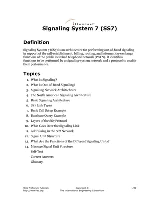
SUs of each type follow a format unique to that type. A high-level view of those
formats is shown in Figure 8.
Figure 8. Signaling Unit Formats
Web ProForum Tutorials Copyright © 15/29
http://www.iec.org The International Engineering Consortium
- 16. All three SU types have a set of common fields that are used by MTP Level 2.
They are as follows:
Flag
Flags delimit SUs. A flag marks the end of one SU and the start of the next.
Checksum
The checksum is an 8-bit sum intended to verify that the SU has passed across
the link error-free. The checksum is calculated from the transmitted message by
the transmitting signaling point and inserted in the message. On receipt, it is
recalculated by the receiving signaling point. If the calculated result differs from
the received checksum, the received SU has been corrupted. A retransmission is
requested.
Length Indicator
The length indicator indicates the number of octets between itself and the
checksum. It serves both as a check on the integrity of the SU and as a means of
discriminating between different types of SUs at level 2. As can be inferred from
Figure 8, FISUs have a length indicator of 0; LSSUs have a length indicator of 1
or 2 (currently all LSSUs have a length indicator of 1), and MSUs have a length-
indicator greater than 2. According to the protocol, only 6 of the 8 bits in the
length indicator field are actually used to store this length; thus the largest value
that can be accommodated in the length indicator is 63. For MSUs with more
than 63 octets following the length indicator, the value of 63 is used.
BSN/BIB FSN/FIB
These octets hold the backwards sequence number (BSN), the backwards
indicator bit (BIB), the forward sequence number (FSN), and the forward
indicator bit (FIB). These fields are used to confirm receipt of SUs and to ensure
that they are received in the order in which they were transmitted. They also are
used to provide flow control. MSUs and LSSUs, when transmitted, are assigned a
sequence number that is placed in the forward sequence number field of the
outgoing SU. This SU is stored by the transmitting signaling point until it is
acknowledged by the receiving signaling point.
Because the seven bits allocated to the forward sequence number can store 128
distinct values, it follows that a signaling point is restricted to sending 128
unacknowledged SUs before it must await an acknowledgment. By
acknowledging an SU, the receiving node frees that SU's sequence number at the
Web ProForum Tutorials Copyright © 16/29
http://www.iec.org The International Engineering Consortium
- 17. transmitting node, making it available for a new outgoing SU. Signaling points
acknowledge receipt of SUs by placing the sequence number of the last correctly
received and in-sequence SU in the backwards sequence number of every SU they
transmit. In that way, they acknowledge all previously received SUs as well. The
forward and backwards indicator bits are used to indicate sequencing or data-
corruption errors and to request retransmission.
13. What are the Functions of the
Different Signaling Units?
FISUs themselves have no information payload. Their purpose is to occupy the
link at those times when there are no LSSUs or MSUs to send. Because they
undergo error checking, FISUs facilitate the constant monitoring of link quality
in the absence of signaling traffic. FISUs also can be used to acknowledge the
receipt of messages using the backwards sequence number and backwards
indicator bit.
LSSUs are used to communicate information about the signaling link between the
nodes on either end of the link. This information is contained in the status field of
the SU (see Figure 8). Because the two ends of a link are controlled by
independent processors, there is a need to provide a means for them to
communicate. LSSUs provide the means for performing this function. LSSUs are
used primarily to signal the initiation of link alignment, the quality of received
signaling traffic, and the status of the processors at either end of the link. Because
they are sent only between the signaling points at either end of the link, LSSUs do
not require any addressing information.
MSUs are the workhorses of the SS7 network. All signaling associated with call
setup and tear down, database query and response, and SS7 network
management takes place using MSUs. MSUs are the basic envelope within which
all addressed signaling information is placed. As will be shown below, there are
several different types of MSUs. All MSUs have certain fields in common. Other
fields differ according to the type of message. The type of MSU is indicated in the
service-information octet shown in Figure 8; the addressing and informational
content of the MSU is contained in the signaling information field.
14. Message Signal Unit Structure
The functionality of the message signal unit lies in the actual content of the
service information octet and the signaling information field (see Figure 8).
The service information octet is an 8-bit field (as might be inferred from its
name) that contains three types of information as follows:
Web ProForum Tutorials Copyright © 17/29
http://www.iec.org The International Engineering Consortium
- 18. 1. four bits are used to indicate the type of information contained in
the signaling information field; they are referred to as the service
indicator; the values most commonly used in American networks
are outlined in Table 1
Table 1. Common Signaling Indicator Values
Value Function
0 signaling network management
1 signaling network testing and
maintenance
3 signaling connection control part (SCCP)
5 ISDN user part (ISUP)
2. two bits are used to indicate whether the message is intended (and
coded) for use in a national or international network; they are
generally coded with a value of 2, national network
3. the remaining 2 bits are used (in American networks) to identify a
message priority, from 0 to 3, with 3 being the highest priority;
message priorities do not control the order in which messages are
transmitted; they are only used in cases of signaling network
congestion; in that case, they indicate whether a message has
sufficient priority to merit transmission during an instance of
congestion or whether it can be discarded en route to a destination
The format of the contents of the signaling information field is determined by the
service indicator. (Within user parts, there are further distinctions in message
formats, but the service indicator provides the first piece of information
necessary for routing or decoding the message.)
The first portion of the signaling information field is identical for all MSUs
currently in use. It is referred to as the routing label. Simply stated, the routing
label identifies the message originator, the intended destination of the message,
and a field referred to as the signaling-link selection field which is used to
distribute message traffic over the set of possible links and routes. The routing
label consists of 7 octets that are outlined below in Table 2 (in order of
transmission).
Web ProForum Tutorials Copyright © 18/29
http://www.iec.org The International Engineering Consortium
- 19. Table 2. Routing Label
Number of Octets
Octet Group Function Involved
destination point contains the address of 3 octets
code (DPC) the node to which the
message is being sent
originating point contains the address of 3 octets
code (OPC) message originator
signaling link distributes load among 1 octet
selection (SLS) redundant routes
Point codes consist of the three-part identifier (network number, cluster number,
member number), which uniquely identifies a signaling point.
Self-Test
1. The signaling of SS7 features _____ signaling.
a. in-band
b. out-of-band
2. SS7 _____ multifrequency tones for signaling.
a. uses
b. does not use
3. Associated signaling _____ for signaling to network elements to which there
is no direct trunk connection.
a. allows
b. does not allow
4. SSPs _____ the packet switches of the SS7 network.
a. are
b. are not
Web ProForum Tutorials Copyright © 19/29
http://www.iec.org The International Engineering Consortium
- 20. Questions 5–7: Identify elements of this figure.
5. Element symbol one is __________.
a. SSP
b. STP
c. SCP
6. Element symbol two is _____________.
a. SSP
b. STP
c. SCP
7. Element symbol three is ______________.
a. SSP
b. STP
c. SCP
8. STPs and SCPs are not customarily deployed in pairs.
a. true
b. false
9. SCPs are always deployed in pairs.
a. true
b. false
10. A links connect an STP and either an SSP or an SCP.
a. true
Web ProForum Tutorials Copyright © 20/29
http://www.iec.org The International Engineering Consortium
- 21. b. false
11. An ACM indicates that an IAM has reached the called subscriber's switch and
that the subscriber is not busy.
a. true
b. false
12. An IAM indicates that a call has reached its proper destination.
a. true
b. false
13. When a called subscriber picks up the phone, his or her switch sends an ANM
to indicate that the trunks should be connected in both directions.
a. true
b. false
14. An REL is a message that indicates that switches at both ends have released
the trunk.
a. true
b. false
15. All 800 numbers are assigned to a subscriber line themselves.
a. true
b. false
16. Dialing an 800 number causes the switch to suspend a call and query a
database for further instructions.
a. true
b. false
17. Links that connect nonmated STP pairs in different networks may be referred
to as ______________.
a. B links
b. D links
Web ProForum Tutorials Copyright © 21/29
http://www.iec.org The International Engineering Consortium
- 22. c. B/D links
d. any of the above
18. MTP management messages and ISUP call setup messages are addressed to
________________.
a. separate applications
b. a signal connection control port
c. B links
d. a node as a whole
19. The SCCP supports __________________.
a. routing to subsystems
b. global title translation
c. load sharing among SCPs
d. all of the above and other functions as well
20. Signaling units are broken up into units of how many bits?
a. 8
b. 16
c. 32
d. 64
Correct Answers
1. The signaling of SS7 features _____ signaling.
a. in-band
b. out-of-band
See Topic 1.
Web ProForum Tutorials Copyright © 22/29
http://www.iec.org The International Engineering Consortium
- 23. 2. SS7 _____ multifrequency tones for signaling.
a. uses
b. does not use
See Topic 2.
3. Associated signaling _____ for signaling to network elements to which there
is no direct trunk connection.
a. allows
b. does not allow
See Topic 2.
4. SSPs _____ the packet switches of the SS7 network.
a. are
b. are not
See Topic 4.
Questions 5–7: Identify elements of this figure.
5. Element symbol one is _________________.
a. SSP
b. STP
c. SCP
See Topic 4.
6. Element symbol two is _______________.
a. SSP
b. STP
Web ProForum Tutorials Copyright © 23/29
http://www.iec.org The International Engineering Consortium
- 24. c. SCP
See Topic 4.
7. Element symbol three is ____________________.
a. SSP
b. STP
c. SCP
See Topic 4.
8. STPs and SCPs are not customarily deployed in pairs.
a. true
b. false
See Topic 4.
9. SCPs are always deployed in pairs.
a. true
b. false
See Topic 4.
10. A links connect an STP and either an SSP or an SCP.
a. true
b. false
See Topic 6.
11. An ACM indicates that an IAM has reached the called subscriber's switch and
that the subscriber is not busy.
a. true
b. false
See Topic 7.
Web ProForum Tutorials Copyright © 24/29
http://www.iec.org The International Engineering Consortium
- 25. 12. An IAM indicates that a call has reached its proper destination.
a. true
b. false
See Topic 7.
13. When a called subscriber picks up the phone, his or her switch sends an ANM
to indicate that the trunks should be connected in both directions.
a. true
b. false
See Topic 7.
14. An REL is a message that indicates that switches at both ends have released
the trunk.
a. true
b. false
See Topic 7.
15. All 800 numbers are assigned to a subscriber line themselves.
a. true
b. false
See Topic 8.
16. Dialing an 800 number causes the switch to suspend a call and query a
database for further instructions.
a. true
b. false
See Topic 8.
17. Links that connect nonmated STP pairs in different networks may be referred
to as ________________.
a. B links
Web ProForum Tutorials Copyright © 25/29
http://www.iec.org The International Engineering Consortium
- 26. b. D links
c. B/D links
d. any of the above
See Topic 6.
18. MTP management messages and ISUP call setup messages are addressed to
__________.
a. separate applications
b. a signal connection control port
c. B links
d. a node as a whole
See Topic 9.
19. The SCCP supports _________________.
a. routing to subsystems
b. global title translation
c. load sharing among SCPs
d. all of the above and other functions as well
See Topic 9.
20. Signaling units are broken up into units of how many bits?
a. 8
b. 16
c. 32
d. 64
See Topic 10.
Web ProForum Tutorials Copyright © 26/29
http://www.iec.org The International Engineering Consortium
- 27. Glossary
ACM
address complete message
ANM
answer message
A links
access links
BIB
backward indicator bit
B links
bridge links
BSN
backward sequence number
D links
diagonal links
DPC
destination point code
E link
extended link
F link
fully associated link
FIB
forward indicator bit
FISU
fill in signal unit
FSN
forward sequence number
IAM
initial address message
ISDN
integrated services digital network
Web ProForum Tutorials Copyright © 27/29
http://www.iec.org The International Engineering Consortium
- 28. ISUP
ISDN user part
kbps
kilobits per second
LSSU
link status signal unit
MF
multifrequency
MSU
message signal unit
MTP
message transfer part
OMAP
operations, maintenance, and administration part
OPC
originating point code
PSTN
public switched telephone network
RBOC
regional Bell operating company
REL
release message
RCL
release complete message
RSP
route set prohibited test message
RSR
restricted test message
SS7
signaling system 7
SCCP
signaling connection control part
Web ProForum Tutorials Copyright © 28/29
http://www.iec.org The International Engineering Consortium
- 29. SCP
signal control point
SLS
signaling link selection
SSP
signal switching point
STP
signal transfer point
SU
signal unit
TCAP
transaction capabilities application part
TFA
transfer allowed message
TFP
transfer prohibited message
TFR
transfer restricted message
Web ProForum Tutorials Copyright © 29/29
http://www.iec.org The International Engineering Consortium