DAIKIN VRV PIPE SELECTION CHART
•
3 likes•6,456 views

BY USING USING THIS , YOU CAN SELECT PIPE SIZE OF DAIKIN MADE VRV SYSTEM
![EDIN341106InstallationManual
InstallationofOutdoorUnits421
16
9English
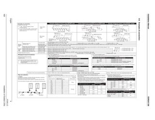
How to calculate the additional
refrigerant to be charged
Additional refrigerant to be charged : R (kg)
(R should be rounded off in units of 0.1 kg.)
Example for refrigerant branch using REFNET joint and REFNET header for the systems and each pipe length as shown below.
Outdoor system : RXYQ34P~
Total capacity of indoor unit : 116%
a : φ19.1 × 30m
b : φ15.9 × 10m
c : φ9.5 × 10m
d : φ9.5 × 10m
e : φ9.5 × 10m
f : φ9.5 × 10m
g : φ6.4 × 10m
h : φ6.4 × 20m
i : φ12.7 × 10m
j : φ6.4 × 10m
k : φ6.4 × 9m
MODEL NAME
THE AMOUNT OF
REFRIGERANT
RX(Y)Q5P
RX(Y)Q8 ~ 12P
RX(Y)Q14 ~ 22P
RX(Y)Q24 ~ 30P
RX(Y)Q32 ~ 38P
RX(Y)Q40 ~ 48P
RX(Y)Q50 ~ 54P
0kg
0.5kg
1.0kg
1.5kg
2.0kg
2.5kg
3.0kg
TABLE B
MODEL NAME [RX(Y)Q ~ P]INDOOR CONNECTION
CAPACITY [X]
X ≤ 100%
100% < X ≤ 120%
120% < X ≤ 130%
130% < X ≤ 140%
140% < X ≤ 150%
150% < X ≤ 160%
160% < X ≤ 170%
170% < X ≤ 180%
180% < X ≤ 190%
190% < X ≤ 200%
5P~8P 12P~14P 18P~22P 24P~28P 30P~32P 42P~44P 46P~48P 52P~54P10P 16P 34P 36P 38P 40P 50P
0.5kg
0.5kg
0.5kg
0.5kg
1.0kg
1.0kg
1.0kg
1.5kg 2.0kg
2.5kg
2.5kg
3.0kg
3.5kg
0.5kg 1.0kg 1.5kg 2.0kg 2.5kg
0.5kg
0.5kg
1.0kg 1.5kg
1.0kg 2.0kg 4.0kg1.5kg 2.5kg 3.0kg 3.5kg
1.5kg 2.0kg 2.5kg 3.0kg
1.5kg 2.0kg
0.5kg 1.0kg
1.0kg 1.5kg 2.0kg
0kg
0.5kg
TABLE A
R = ( 30 × 0.26 + 10 × 0.18 + 10 × 0.12 + 40 × 0.059 + 49 × 0.022 )+ 2.0 + 0.5
a b i RXYQ34P~ 116%
= 16.738 16.7kg
Round off units of 0.1 kg.
c+d+e+f g+h+i+j+k
∗Note 1
When the equivalent pipe length between outdoor and indoor
units is 90m or more, the size of main pipes (both gas-side and
liquid-side) must be increased.
Depending on the length of the piping, the capacity may drop, but
even in such case it is able to increase the size of main pipes.
(Refer to figure 9)
1. Outdoor unit
2. Main pipes
3. Increase
4. The first refrigerant branch kit
5. Indoor unit
∗Note 2
Allowable length after the first refrigerant branch kit to indoor units is 40 m or less, however it can be extended up to 90 m if all the following conditions are satisfied. (In case of “ Branch with REFNET joint ” )
∗Note 3
If the pipe size above the REFNET header is φ34.9 or more, KHRP26M73HP is required.
n Diameter of above case
Model Gas Liquid
RXYQ5 Type φ19.1 Not Increased
RXYQ8 Type φ22.2 φ12.7
RXYQ10 Type φ25.4* φ12.7
RXYQ12 Type Not Increased φ15.9
RXYQ14 Type Not Increased φ15.9
RXYQ16 Type φ31.8* φ15.9
*If available on the site, use this size.
Otherwise, it can not be increased.
* If available on the site, use
this size.
Otherwise it can not be
increased.
2. For calculation of Total extension length, the actual length of above pipes must be
doubled. (except main pipe and the pipes that are not increased)
3. Indoor unit to the nearest branch kit ≤ 40 m
8 b+c+d+e+f+g+p≤ 90 m
increase the pipe size of b, c, d, e, f, g
a+b×2+c×2+d×2+e×2+f×2+g×2
+h+i+j+k+l+m+n+p≤ 1000 m
h, i, j....... p ≤ 40 m
The farthest indoor unit 8
The nearest indoor unit 1
(a+b+c+d+e+f+g+p)-(a+h)≤ 40 m
Increase the pipe size as follows
φ 9.5 → φ12.7
φ12.7 → φ15.9
φ15.9 → φ19.1
φ19.1 → φ22.2
φ22.2 → φ25.4*
φ28.6 → φ31.8*
φ34.9 → φ38.1*
RXYQ18 Type φ31.8* φ19.1
Model Gas Liquid
RXYQ20 Type φ31.8* φ19.1
RXYQ22 Type φ31.8* φ19.1
RXYQ24 Type Not Increased φ19.1
RXYQ26 Type φ38.1* φ22.2
RXYQ28 Type φ38.1* φ22.2
RXYQ30 Type φ38.1* φ22.2
RXYQ32 Type φ38.1* φ22.2
Model Gas Liquid
RXYQ34 Type φ38.1* φ22.2
RXYQ36 Type Not Increased φ22.2
RXYQ38 Type Not Increased φ22.2
RXYQ40 Type Not Increased φ22.2
RXYQ42 Type Not Increased φ22.2
RXYQ44 Type Not Increased φ22.2
RXYQ46 Type Not Increased φ22.2
Model Gas Liquid
RXYQ48 Type Not Increased φ22.2
RXYQ50 Type Not Increased φ22.2
RXYQ52 Type Not Increased φ22.2
RXYQ54 Type Not Increased φ22.2
a
A B C D E F G
b c d e f g
h i j k l m n
1 2 3 4 5 6 7
8
H1
p
Outdoor unit REFNET joint (A-G)
Indoor units ( 1 - 8 )
R =
REFRIGERANT
AMOUNT FOR
HEAT PUMP SYSTEM
TABLE A
REFRIGERANT AMOUNT
FOR EXCEEDING CONNECTION
CAPACITY OF INDOOR UNIT
TABLE B
Total length(m) of liquid
piping size at φ22.2 0.37
Total length(m) of liquid
piping size at φ19.1 0.26
Total length(m) of liquid
piping size at φ15.9 0.18
Total length(m) of liquid
piping size at φ12.7 0.12
Total length(m) of liquid
piping size at φ9.5 0.059
Total length(m) of liquid
piping size at φ6.4 0.022
C:3P226891-2G](data:image/gif;base64,R0lGODlhAQABAIAAAAAAAP///yH5BAEAAAAALAAAAAABAAEAAAIBRAA7)
Recommended
More Related Content
What's hot
What's hot (20)
Similar to DAIKIN VRV PIPE SELECTION CHART
Similar to DAIKIN VRV PIPE SELECTION CHART (20)
Recently uploaded
Recently uploaded (20)
DAIKIN VRV PIPE SELECTION CHART
- 1. InstallationManualEDIN341106 420InstallationofOutdoorUnits English8 6-5Exampleofconnection Example of connection (Connection of 8 indoor units) Single outdoor system Example refrigerant branch using REFNET joint Example refrigerant branch using REFNET joint and REFNET header Example refrigerant branch using REFNET header a b c d e f g H1 p Outdoor unit REFNET joint (A-G) Indoor units ( 1 - 8 ) H1 H2 a a i b c d e f g h k j 7 8 H1 H2 Outdoor unit REFNET header c d e f g h ib 1 2 3 4 5 6 7 8 Multi outdoor system (∗2) In case of multi outdoor system, re-read to the first Outdoor unit multi connection piping kit as seen from the indoor unit. Maximum allowable length Between outdoor (∗2) and indoor units Between outdoor unit and Outdoor unit multi connection piping kit (Only for multi system) Between outdoor and indoor units Between indoor and indoor units Between outdoor and outdoor units Actual pipe length Actual pipe length Actual pipe length Equivalent length Difference in height Difference in height Difference in height Equivalent length Total extension length Pipe length between outdoor (∗2) and indoor units ≤ 165m Example unit 8 : a + b + c + d + e + f + g + p ≤ 165m Example unit 8 : b + c + d + e + f + g + p ≤ 40m Equivalent pipe length between outdoor (∗2) and indoor units ≤ 190m (assume equivalent pipe length of REFNET joint to be 0.5m, that of REFNET header to be 1m, calculation purposes) (See Note 1 - Next page) Pipe length between outdoor unit and Outdoor unit multi connection piping kit ≤ 10m, Equivalent length between outdoor unit and Outdoor unit multi connection piping kit ≤ 13m Difference in height between outdoor and indoor units (H1) ≤ 50m ( ≤ 90m if the outdoor unit is below) Difference in height between indoor units (H2) ≤ 15m Difference in height between outdoor unit (H3) ≤ 5m Pipe length from first refrigerant branch kit (either REFNET joint or REFNET header ) to indoor unit ≤ 40m (See Note 2 - Next page) Total pipe length from outdoor unit (∗2) to all indoor units ≤ 1000m Allowable height length Allowable length after the branch Refrigerant branch kit selection Pipe size selection Example unit 8 : a + i ≤ 165mExample unit 6 : a + b + h ≤ 165m, unit 8 : a + i + k ≤ 165m Example unit 8 : i ≤ 40mExample unit 6 : b + h ≤ 40m, unit 8 :i + k ≤ 40m r ≤ 10m (Equivalent length: ≤ 13m) s ≤ 10m (Equivalent length: ≤ 13m) t ≤ 10m (Equivalent length: ≤ 13m) Refrigerant branch kits can only be used with R410A. How to select the REFNET joint • When using REFNET joint at the first branch counted from the outdoor unit side. Choose from the following table in accordance with the outdoor unit capacity type. (Example: REFNET joint A) Temper grade and wall thickness for pipes. (Temper grade, O type and 1/2H type indicate the material types specified in JIS H 3300.) Piping between refrigerant branch kits • Choose from the following table in accordance with the total capacity index of all the indoor units connected below this. • Do not let the connection piping exceed the main refrigerant piping size. 5HP type 8, 10HP type 12~22HP type 24HP type~ KHRP26A22T KHRP26A33T KHRP26A72T KHRP26A73T + KHRP26M73TP • Choose the REFNET joints other than that for the first branch from the following table in accordance with the total capacity index of all the indoor units connected below the REFNET joint. How to select the REFNET header • Choose from the following table in accordance with the total capacity index of all the indoor units connected below the REFNET header. • Note: 250 type indoor unit cannot be connected below the REFNET header. < 200 200 ≤ x< 290 290 ≤ x< 640 640 ≤ KHRP26M22H (Max. 4 branch) KHRP26M33H (Max. 8 branch) KHRP26M72H (Max. 8 branch) (See Note 3 - Next page) KHRP26M73H (Max. 8 branch) + KHRP26M73HP How to select the Outdoor unit multi connection piping kit (This is required when the system is multi outdoor unit system.) • Choose from the following table in accordance with the number of outdoor units. 2 units 3 units BHFP22P100 BHFP22P151 Example REFNET joint C: indoor unitsExample for indoor units connected downstream 5HP type 8HP type 10HP type 12~16HP type 18~22HP type 24HP type 26~34HP type 36~54HP type Indoor unit total capacity index < 150 150 ≤ x< 200 200 ≤ x< 290 290 ≤ x< 420 420 ≤ x< 640 640 ≤ x< 920 920 ≤ Piping between refrigerant branch kit and indoor unit • Match to the size of the connection piping on the indoor unit. 20 · 25 · 32 · 40 · 50 type 63 · 80 · 100 · 125 type 200 type 250 type (Unit:mm) (Unit:mm) (Unit:mm) (Unit:mm) (See Note 1 - Next page) Indoor unit total capacity index Refrigerant branch kit name Number of outdoor units Connection piping kit name Outdoor unit capacity type Refrigerant branch kit name Outdoor unit capacity type Gas pipe Indoor unit capacity type Liquid pipe Piping size (O.D.) A B For the multi outdoor unit system, select in accordance with the following figure. (∗1) “ ” indicate the Outdoor unit multi connection piping kit A B C D E F G 1 2 3 4 5 6 7 8 H2 h i j k l m n 1 2 3 4 5 6 Outdoor unit REFNET joint (A • B) REFNET header 3 + 4 + 5 + 6 + 7 + 8 Example REFNET joint B: indoor units Example REFNET header: indoor units 1 + 2 + 3 + 4 + 5 + 6 7 + 8 Example REFNET header: indoor units 1 + 2 + 3 + 4 + 5 + 6 + 7 + 8 Caution φ15.9 φ19.1 φ22.2 φ28.6 φ34.9 φ41.3 φ15.9 φ19.1 φ22.2 φ28.6 φ34.9 φ41.3 φ12.7 φ15.9 φ19.1 φ22.2 φ6.4 φ9.5 φ9.5 φ12.7 φ15.9 φ19.1φ9.5 φ12.7 φ15.9 φ19.1 The thickness of the pipes in the table shows the requirements of Japanese High Pressure Gas Control low. (As of Jan. 2003) The thickness and material shall be selected in accordance with local code. a b c d e f g 8 H2 H1 H3 p Outdoor unit REFNET joint (A-G) h i j k l m n 1 2 3 4 5 6 7 First Outdoor unit multi connection piping kit Indoor units ( 1 - 8 ) Indoor units ( 1 - 8 ) Indoor units ( 1 - 8 ) Part CPart BPart A O type 1/2H type φ6.4 0.80 φ9.5 0.80 φ12.7 0.80 φ15.9 0.99 φ19.1 0.80 φ22.2 0.80 φ25.4 0.88 φ28.6 0.99 φ31.8 1.10 φ34.9 1.21 φ38.1 1.32 φ41.3 1.43 Piping between Outdoor unit and first refrigerant branch kit. Piping between first Outdoor unit multi connection piping kit and first refrigerant branch kit. (Part A) • Choose from the following table in accordance with the outdoor unit capacity type. Piping between Outdoor unit multi connection piping kits. (Part B) Piping between outdoor unit and Outdoor unit multi connection piping kit. (Part C) • Choose from the following table in accordance with the total capacity type of all the outdoor units connected above Outdoor unit multi connection piping kit. • When multi outdoor system are installed, be sure to use the special separately sold Outdoor unit multi connection piping kit. The table at right shows how to select the proper kit. A B C D E F G H1 H2 a i b Outdoor unit c d e f g h 1 2 3 4 5 6 REFNET header k j 7 8 H3 REFNET joint (A • B) A B Indoor units ( 1 - 8 ) H2 8 H1 H3 a Outdoor unit REFNET header c d e f g h ib Indoor units ( 1 - 8 ) 1 2 3 4 5 6 7 r t s Outdoor unit Temper gradeCopper tube O.D. Copper tube W.T. (Minimum requirement) < 200 200 ≤ x< 290 290 ≤ x< 640 640 ≤ KHRP26A22T KHRP26A33T KHRP26A72T KHRP26A73T + KHRP26M73TP Indoor unit total capacity index Refrigerant branch kit name Gas pipe Liquid pipe Piping size (O.D.) Gas pipe Liquid pipe Piping size (O.D.) 3P226891-2G
- 2. EDIN341106InstallationManual InstallationofOutdoorUnits421 16 9English How to calculate the additional refrigerant to be charged Additional refrigerant to be charged : R (kg) (R should be rounded off in units of 0.1 kg.) Example for refrigerant branch using REFNET joint and REFNET header for the systems and each pipe length as shown below. Outdoor system : RXYQ34P~ Total capacity of indoor unit : 116% a : φ19.1 × 30m b : φ15.9 × 10m c : φ9.5 × 10m d : φ9.5 × 10m e : φ9.5 × 10m f : φ9.5 × 10m g : φ6.4 × 10m h : φ6.4 × 20m i : φ12.7 × 10m j : φ6.4 × 10m k : φ6.4 × 9m MODEL NAME THE AMOUNT OF REFRIGERANT RX(Y)Q5P RX(Y)Q8 ~ 12P RX(Y)Q14 ~ 22P RX(Y)Q24 ~ 30P RX(Y)Q32 ~ 38P RX(Y)Q40 ~ 48P RX(Y)Q50 ~ 54P 0kg 0.5kg 1.0kg 1.5kg 2.0kg 2.5kg 3.0kg TABLE B MODEL NAME [RX(Y)Q ~ P]INDOOR CONNECTION CAPACITY [X] X ≤ 100% 100% < X ≤ 120% 120% < X ≤ 130% 130% < X ≤ 140% 140% < X ≤ 150% 150% < X ≤ 160% 160% < X ≤ 170% 170% < X ≤ 180% 180% < X ≤ 190% 190% < X ≤ 200% 5P~8P 12P~14P 18P~22P 24P~28P 30P~32P 42P~44P 46P~48P 52P~54P10P 16P 34P 36P 38P 40P 50P 0.5kg 0.5kg 0.5kg 0.5kg 1.0kg 1.0kg 1.0kg 1.5kg 2.0kg 2.5kg 2.5kg 3.0kg 3.5kg 0.5kg 1.0kg 1.5kg 2.0kg 2.5kg 0.5kg 0.5kg 1.0kg 1.5kg 1.0kg 2.0kg 4.0kg1.5kg 2.5kg 3.0kg 3.5kg 1.5kg 2.0kg 2.5kg 3.0kg 1.5kg 2.0kg 0.5kg 1.0kg 1.0kg 1.5kg 2.0kg 0kg 0.5kg TABLE A R = ( 30 × 0.26 + 10 × 0.18 + 10 × 0.12 + 40 × 0.059 + 49 × 0.022 )+ 2.0 + 0.5 a b i RXYQ34P~ 116% = 16.738 16.7kg Round off units of 0.1 kg. c+d+e+f g+h+i+j+k ∗Note 1 When the equivalent pipe length between outdoor and indoor units is 90m or more, the size of main pipes (both gas-side and liquid-side) must be increased. Depending on the length of the piping, the capacity may drop, but even in such case it is able to increase the size of main pipes. (Refer to figure 9) 1. Outdoor unit 2. Main pipes 3. Increase 4. The first refrigerant branch kit 5. Indoor unit ∗Note 2 Allowable length after the first refrigerant branch kit to indoor units is 40 m or less, however it can be extended up to 90 m if all the following conditions are satisfied. (In case of “ Branch with REFNET joint ” ) ∗Note 3 If the pipe size above the REFNET header is φ34.9 or more, KHRP26M73HP is required. n Diameter of above case Model Gas Liquid RXYQ5 Type φ19.1 Not Increased RXYQ8 Type φ22.2 φ12.7 RXYQ10 Type φ25.4* φ12.7 RXYQ12 Type Not Increased φ15.9 RXYQ14 Type Not Increased φ15.9 RXYQ16 Type φ31.8* φ15.9 *If available on the site, use this size. Otherwise, it can not be increased. * If available on the site, use this size. Otherwise it can not be increased. 2. For calculation of Total extension length, the actual length of above pipes must be doubled. (except main pipe and the pipes that are not increased) 3. Indoor unit to the nearest branch kit ≤ 40 m 8 b+c+d+e+f+g+p≤ 90 m increase the pipe size of b, c, d, e, f, g a+b×2+c×2+d×2+e×2+f×2+g×2 +h+i+j+k+l+m+n+p≤ 1000 m h, i, j....... p ≤ 40 m The farthest indoor unit 8 The nearest indoor unit 1 (a+b+c+d+e+f+g+p)-(a+h)≤ 40 m Increase the pipe size as follows φ 9.5 → φ12.7 φ12.7 → φ15.9 φ15.9 → φ19.1 φ19.1 → φ22.2 φ22.2 → φ25.4* φ28.6 → φ31.8* φ34.9 → φ38.1* RXYQ18 Type φ31.8* φ19.1 Model Gas Liquid RXYQ20 Type φ31.8* φ19.1 RXYQ22 Type φ31.8* φ19.1 RXYQ24 Type Not Increased φ19.1 RXYQ26 Type φ38.1* φ22.2 RXYQ28 Type φ38.1* φ22.2 RXYQ30 Type φ38.1* φ22.2 RXYQ32 Type φ38.1* φ22.2 Model Gas Liquid RXYQ34 Type φ38.1* φ22.2 RXYQ36 Type Not Increased φ22.2 RXYQ38 Type Not Increased φ22.2 RXYQ40 Type Not Increased φ22.2 RXYQ42 Type Not Increased φ22.2 RXYQ44 Type Not Increased φ22.2 RXYQ46 Type Not Increased φ22.2 Model Gas Liquid RXYQ48 Type Not Increased φ22.2 RXYQ50 Type Not Increased φ22.2 RXYQ52 Type Not Increased φ22.2 RXYQ54 Type Not Increased φ22.2 a A B C D E F G b c d e f g h i j k l m n 1 2 3 4 5 6 7 8 H1 p Outdoor unit REFNET joint (A-G) Indoor units ( 1 - 8 ) R = REFRIGERANT AMOUNT FOR HEAT PUMP SYSTEM TABLE A REFRIGERANT AMOUNT FOR EXCEEDING CONNECTION CAPACITY OF INDOOR UNIT TABLE B Total length(m) of liquid piping size at φ22.2 0.37 Total length(m) of liquid piping size at φ19.1 0.26 Total length(m) of liquid piping size at φ15.9 0.18 Total length(m) of liquid piping size at φ12.7 0.12 Total length(m) of liquid piping size at φ9.5 0.059 Total length(m) of liquid piping size at φ6.4 0.022 C:3P226891-2G