SlideShare a Scribd company logo
1 of 43
Introduction to Mechanism
Machines are mechanical devices used to accomplish
work. A mechanism is a heart of a machine. It is the
mechanical portion of the machine that has the
function of transferring motion and forces from a
power source to an output.
Mechanism is a system of rigid elements (linkages)
arranged and connected to transmit motion and/or
force in a predetermined fashion.
Mechanism consists of linkages and joints.
Introduction
Vehicle Frame
High Rise Building
Bridge Supporting
Roadway
Residential Dwelling
Structures can be seen all
around us in our everyday lives.
Structure or Mechanism?
• Can you identify a
Structure within this
bicycle?
• Can you name a
mechanisms on this
bicycle?
Frame = Structure
Chain and Sprocket = One
example of a mechanism
Introduction
Machinery is a central part
of life today.
How many can you
identify?
Drill Tractor
Car Luas Exercise Bicycle
Introduction
Rack and Pinion Pulley Wheels
Cam and Follower
All these machines have working parts called –
Mechanisms
Example of Mechanism
Can crusher
Simple press
Rear-window wiper
Example of Mechanisms
Moves packages from an assembly
bench to a conveyor
Lift platform
Microwave carrier to assist
people on wheelchair
Example of Mechanisms
Lift platform
Front loader
Device to close the
top flap of boxes
9
Example of Mechanisms
Stair climbing mechanism
A box that
turns itself off
Airplane landing
gear mechanism
Mechanisms and Motion
Mechanism
A system of moving parts
that performs some
function.
Motion
The process of
continual change in
the position of an
object “movement”
Motion
There are four main types of motion.
Linear motion – Train
Oscillating Motion – Pendulum of a clock
Reciprocating Motion – Hacksaw
Rotary Motion - Shaft
Pendulum
Train
Shaft
• A kinematic chain is defined as:
An assemblage of links and joints, interconnected in a way
to provide a controlled output motion in response to a
supplied input motion.
• A mechanism is defined as:
A kinematic chain in which at least one link has been
“grounded,” or attached, to the frame of reference (which
itself may be in motion).
• A machine is defined as:
A combination of resistant bodies arranged to compel the
mechanical forces of nature to do work accompanied by
determinate motions.
The similarity between machines and
mechanisms is that
• They are both combinations of rigid bodies
• The relative motion among the rigid bodies
are definite.
• The difference between machine and
mechanism is that machines transform energy
to do work, while mechanisms so not
necessarily perform this function.
• The term machinery generally means
machines and mechanisms. The mechanism of
its cylinder-link-crank parts is a slider-crank
mechanism.
Links, kinematic Pair and Chains
• A link is defined as a rigid body having two or
more pairing elements which connect it to
other bodies for the purpose of transmitting
force or motion.
• A joint of two links having relative motion
between them is known as a kinematic pair.
• The combination of links and pairs without a
fixed link is not a mechanism but a kinematic
chain.
LINKS
• A link, as shown in Figure is an (assumed) rigid body that possesses at
least two nodes that are points for attachment to other links.
• Binary link - one with two nodes.
• Ternary link - one with three nodes.
• Quaternary link - one with four nodes.
Types of Link
Primary Joints
Higher Order Joints
Ken Youssefi Mechanical Engineering Dept. 20
Type of Motion and Mechanisms
Translation to Translation
Most power sources that are readily available today are either of the pure
rotational motion type, such as electric motor or hand crank, or of the
pure translational type, such as pneumatic or hydraulic cylinder, or linear
actuators.
Type of Motion and Mechanisms
Rotational to Rotational
Type of Motion and Mechanisms
Rotation to Translation
Classification of kinematic Pairs
• According to nature of contact between links.
i) Lower Pair ii) Higher pair
• According to type of relative motion between the links.
i) Sliding Pair ii) Turning Pair iii) Rolling Pair iv) Screw Pair
v) Spherical Pair
• According to nature of mechanical constraint between
two links.
i) Closed Pair ii) Unclosed Pair
Acc. to the nature of contact
1. Lower pair – When the two links have surface contact between them, it is
known as lower pair.
2. Higher pair - When the two links have line or point contact between
them, it is known as lower pair.
Acc. to nature of relative motion
1. Sliding pair – When one link slides relative to another link, it is known as
sliding pair.
2. Turning pair – When one link turns or revolve relative to another link, it is
known as turning pair
3. Rolling pair – When one link rolls over the other pair, it is known as
rolling pair.
4. Screw pair – If two pairs have turning as well as rolling motion between
them, it is known as screw pair.
5. Spherical pair – When a spherical link turns inside a fixed link, it is known
as spherical pair.
Acc. to nature of constraint
1. Self closed pair – When the two links are joined together mechanically, it
is known as self closed pair.
2. Unclosed pair – When the two links are connected either due to gravity
or by some external forces, it is known as unclosed pair.
Lower Pair
A kinematic pair is
said to be a lower
pair if the links in
the pair have
surface or area
contact between
them.
Along with a cylinder, a piston forms a lower
pair
Higher Pair
A higher pair is a
kinematic pair in
which the links have
point or line contact.
Ball bearings, cam and
follower are examples
of higher pair.
Ball Bearings
Sliding Pair
As the name suggests, a
sliding pair is a kinematic
pair in which each element
has sliding contact with
respect to the other
element. Some good
examples of sliding pairs
are piston inside a cylinder,
spur gear drive and square
bar in a square hole.
Square Bar in a Square Hole – An example of
Sliding Pair
Rolling Pair
In a rolling pair, one
element undergoes
rolling motion with
respect to the other.
Wheel rolling on a flat surface – An example
of Rolling Pair
Turning Pair
In a turning pair, one
link undergoes turning
motion relative to the
other link. Example is
a shaft with collars in a
circular hole.
Screw pair
A screw pair consists
of links that have both
turning and sliding
motion relative to
each other
Bolt and Nut – An Example of Screw Pair
Cylindrical Pair
A cylindrical pair is a
kinematic pair in
which the links
undergo both
rotational and
translational motion
relative to one
another.
Spherical Pair
In a spherical
pair, a
spherical link
turns inside a
fixed link.
Completely constrained motion
Completely constrained
motion is a type of
constrained motion in
which relative motion
between the links of a
kinematic pair occurs in a
definite direction by itself,
irrespective of the external
forces applied.
Square bar in a square hole undergoes
completely constrained motion.
Incompletely constrained motion
In incompletely
constrained motion, the
relative motion between
the links depend on the
direction of external forces
acting on them. A good
example of incompletely
constrained motion is the
motion of a shaft inside a
circular hole. Depending
on the direction of external
forces applied, the shaft
may slide or turn (or do
both) inside the circular
hole.
Shaft in a circular hole
Partially (or successfully) constrained motion
A kinematic pair is said to be partially
or successfully constrained if the
relative motion between its links
occurs in a definite direction, not by
itself, but by some other means. A
good example of successfully
constrained motion is piston
reciprocating inside a cylinder in an
internal combustion engine.
Normally, when a piston is placed in a
cylinder, it may undergo reciprocating
motion (upward and downward
motion) and turning motion,
depending on the external forces
applied. It is incompletely constrained.
However, if the piston is connected to
a connecting rod, its motion is
successfully constrained i.e., it can
only undergo only reciprocating
motion inside the cylinder. Here, some
other means (i.e., connecting rod) is
used for successfully constraining the
motion of the piston.
A Piston
Types of Joints
•Binary Joint
•Ternary Joint
•Quaternary Joint
THE GRASHOF CONDITION
• The Grashof condition is a very simple relationship that
predicts the rotation behavior or rotatability of a fourbar
linkage’s inversions based only on the link lengths.
• The linkage is Grashof and at least one link will be capable of
making a full revolution with respect to the ground plane. This
is called a Class I kinematic chain. If the inequality is not true,
then the linkage is non-Grashof and no link will be capable of a
complete revolution relative to any other link. This is a Class II
kinematic chain.
THEORY OF MACHINES AND
MECHANISMS
John J. Uicker, Jr. / Gordon R. Pennock
Copyright © 2011 by
Oxford University Press, Inc.
Figure 1.28 Four inversions of the Grashof chain: (a, b) crank-rocker mechanisms, (c)
draglink mechanism, and (d) double-rocker mechanism.
• For the Class I case, S + L < P + Q:
• Ground either link adjacent to the shortest and you get
a crank-rocker, in which the shortest link will fully
rotate and the other link pivoted to ground will oscillate.
Ground the shortest link and you will get a double-
crank, in which both links pivoted to ground make
complete revolutions as does the coupler.
• Ground the link opposite the shortest and you will get a
Grashof double-rocker, in which both links pivoted to
ground oscillate and only the coupler makes a full
revolution.
• For the Class II case, S + L > P + Q:
• All inversions will be triple-rockers in which no link can
fully rotate.
• For the Class III case, S + L = P + Q:

More Related Content

What's hot

Gear manufacturing process
Gear manufacturing processGear manufacturing process
Gear manufacturing process
KANNANS94
 

What's hot (20)

Introduction of machines and mechanism
Introduction of machines and mechanismIntroduction of machines and mechanism
Introduction of machines and mechanism
 
Kom ppt unit1
Kom ppt unit1Kom ppt unit1
Kom ppt unit1
 
Theory of machine
Theory of machine Theory of machine
Theory of machine
 
INVERSION OF MECHANISM
INVERSION OF MECHANISMINVERSION OF MECHANISM
INVERSION OF MECHANISM
 
Tom[unit 1]
Tom[unit 1]Tom[unit 1]
Tom[unit 1]
 
Spur gears
Spur gearsSpur gears
Spur gears
 
Introduction to Mechanisms
Introduction to MechanismsIntroduction to Mechanisms
Introduction to Mechanisms
 
Work holding devices of lathe
Work holding devices of latheWork holding devices of lathe
Work holding devices of lathe
 
Fundamentals of Kinematics and Mechanisms
Fundamentals of Kinematics and MechanismsFundamentals of Kinematics and Mechanisms
Fundamentals of Kinematics and Mechanisms
 
Unit 1 Introduction & Basics of mechanism
Unit 1 Introduction & Basics of mechanismUnit 1 Introduction & Basics of mechanism
Unit 1 Introduction & Basics of mechanism
 
Applications of Belt, Rope and Chain Drives
Applications of Belt, Rope and Chain DrivesApplications of Belt, Rope and Chain Drives
Applications of Belt, Rope and Chain Drives
 
Gear design , classification advantages and disadvantages
Gear design , classification  advantages and disadvantages Gear design , classification  advantages and disadvantages
Gear design , classification advantages and disadvantages
 
Lecture 2. linkages
Lecture 2. linkagesLecture 2. linkages
Lecture 2. linkages
 
Module 2 instantenous center method
Module 2 instantenous center methodModule 2 instantenous center method
Module 2 instantenous center method
 
Unit 2b Power Transmission by Belts
Unit 2b Power Transmission by BeltsUnit 2b Power Transmission by Belts
Unit 2b Power Transmission by Belts
 
Mechanics of machines: Linkage Mechanisms
Mechanics of machines: Linkage MechanismsMechanics of machines: Linkage Mechanisms
Mechanics of machines: Linkage Mechanisms
 
Chain drive system
Chain drive systemChain drive system
Chain drive system
 
Balancing of rotating masses
Balancing of rotating massesBalancing of rotating masses
Balancing of rotating masses
 
Gear manufacturing process
Gear manufacturing processGear manufacturing process
Gear manufacturing process
 
KInematic of Machine(Mechanical Engineering)
KInematic of Machine(Mechanical Engineering)KInematic of Machine(Mechanical Engineering)
KInematic of Machine(Mechanical Engineering)
 

Similar to Introduction to mechanism

ME 223-THEORY OF MACHINER.pptx
ME 223-THEORY OF MACHINER.pptxME 223-THEORY OF MACHINER.pptx
ME 223-THEORY OF MACHINER.pptx
AnupKashyap10
 
KInematics of mc links pairs.pptx
KInematics of mc links pairs.pptxKInematics of mc links pairs.pptx
KInematics of mc links pairs.pptx
AniketPandey85
 
Met 305 tutorial-0_simple_mechanisms
Met 305 tutorial-0_simple_mechanismsMet 305 tutorial-0_simple_mechanisms
Met 305 tutorial-0_simple_mechanisms
hotman1991
 
Notes.docx
Notes.docxNotes.docx
Notes.docx
Ravichandran R
 

Similar to Introduction to mechanism (20)

ME 223-THEORY OF MACHINER.pptx
ME 223-THEORY OF MACHINER.pptxME 223-THEORY OF MACHINER.pptx
ME 223-THEORY OF MACHINER.pptx
 
Kinematics of Machinery
Kinematics of MachineryKinematics of Machinery
Kinematics of Machinery
 
TOM Study materials -Unit 1-5 .pdf
TOM Study materials -Unit 1-5 .pdfTOM Study materials -Unit 1-5 .pdf
TOM Study materials -Unit 1-5 .pdf
 
Fundamentals and types of mechanisms
Fundamentals and types of mechanismsFundamentals and types of mechanisms
Fundamentals and types of mechanisms
 
Planer Mechanism
Planer MechanismPlaner Mechanism
Planer Mechanism
 
Mechanism and machines, Inversion, Link pair chain, Kinematics of machine, de...
Mechanism and machines, Inversion, Link pair chain, Kinematics of machine, de...Mechanism and machines, Inversion, Link pair chain, Kinematics of machine, de...
Mechanism and machines, Inversion, Link pair chain, Kinematics of machine, de...
 
Kinematics of Machine study material
Kinematics of Machine study material Kinematics of Machine study material
Kinematics of Machine study material
 
KInematics of mc links pairs.pptx
KInematics of mc links pairs.pptxKInematics of mc links pairs.pptx
KInematics of mc links pairs.pptx
 
Module 1 mechanisms and machines
Module 1  mechanisms and machinesModule 1  mechanisms and machines
Module 1 mechanisms and machines
 
MODULE-1 INTRODUCTION.pptx
MODULE-1 INTRODUCTION.pptxMODULE-1 INTRODUCTION.pptx
MODULE-1 INTRODUCTION.pptx
 
Met 305 tutorial-0_simple_mechanisms
Met 305 tutorial-0_simple_mechanismsMet 305 tutorial-0_simple_mechanisms
Met 305 tutorial-0_simple_mechanisms
 
Introduction to Machine.pptx
Introduction to Machine.pptxIntroduction to Machine.pptx
Introduction to Machine.pptx
 
Material and mechanical 5082_Lecture_1.pdf
Material and mechanical 5082_Lecture_1.pdfMaterial and mechanical 5082_Lecture_1.pdf
Material and mechanical 5082_Lecture_1.pdf
 
Kinematics of machines
Kinematics of machines Kinematics of machines
Kinematics of machines
 
THEORY OF MACHINES
THEORY OF MACHINESTHEORY OF MACHINES
THEORY OF MACHINES
 
theory of machine
theory of machinetheory of machine
theory of machine
 
Notes.docx
Notes.docxNotes.docx
Notes.docx
 
Notes.docx
Notes.docxNotes.docx
Notes.docx
 
Unit -1 Mechanisms
Unit -1 MechanismsUnit -1 Mechanisms
Unit -1 Mechanisms
 
module1introductiontokinematics-181227112050.pptx
module1introductiontokinematics-181227112050.pptxmodule1introductiontokinematics-181227112050.pptx
module1introductiontokinematics-181227112050.pptx
 

More from rajat_jubilee (9)

Solar energy
Solar energySolar energy
Solar energy
 
Turbomacinery
TurbomacineryTurbomacinery
Turbomacinery
 
Manufacturing process ii
Manufacturing process iiManufacturing process ii
Manufacturing process ii
 
Gears and pulleys engineering diagrams
Gears and pulleys engineering diagramsGears and pulleys engineering diagrams
Gears and pulleys engineering diagrams
 
Combustion
CombustionCombustion
Combustion
 
Chapter 8
Chapter 8Chapter 8
Chapter 8
 
Ch06a
Ch06aCh06a
Ch06a
 
Cams
CamsCams
Cams
 
Belt drive
Belt driveBelt drive
Belt drive
 

Recently uploaded

DeepFakes presentation : brief idea of DeepFakes
DeepFakes presentation : brief idea of DeepFakesDeepFakes presentation : brief idea of DeepFakes
DeepFakes presentation : brief idea of DeepFakes
MayuraD1
 
Cara Menggugurkan Sperma Yang Masuk Rahim Biyar Tidak Hamil
Cara Menggugurkan Sperma Yang Masuk Rahim Biyar Tidak HamilCara Menggugurkan Sperma Yang Masuk Rahim Biyar Tidak Hamil
Cara Menggugurkan Sperma Yang Masuk Rahim Biyar Tidak Hamil
Cara Menggugurkan Kandungan 087776558899
 
Integrated Test Rig For HTFE-25 - Neometrix
Integrated Test Rig For HTFE-25 - NeometrixIntegrated Test Rig For HTFE-25 - Neometrix
Integrated Test Rig For HTFE-25 - Neometrix
Neometrix_Engineering_Pvt_Ltd
 
Kuwait City MTP kit ((+919101817206)) Buy Abortion Pills Kuwait
Kuwait City MTP kit ((+919101817206)) Buy Abortion Pills KuwaitKuwait City MTP kit ((+919101817206)) Buy Abortion Pills Kuwait
Kuwait City MTP kit ((+919101817206)) Buy Abortion Pills Kuwait
jaanualu31
 
Hospital management system project report.pdf
Hospital management system project report.pdfHospital management system project report.pdf
Hospital management system project report.pdf
Kamal Acharya
 

Recently uploaded (20)

Navigating Complexity: The Role of Trusted Partners and VIAS3D in Dassault Sy...
Navigating Complexity: The Role of Trusted Partners and VIAS3D in Dassault Sy...Navigating Complexity: The Role of Trusted Partners and VIAS3D in Dassault Sy...
Navigating Complexity: The Role of Trusted Partners and VIAS3D in Dassault Sy...
 
A Study of Urban Area Plan for Pabna Municipality
A Study of Urban Area Plan for Pabna MunicipalityA Study of Urban Area Plan for Pabna Municipality
A Study of Urban Area Plan for Pabna Municipality
 
DeepFakes presentation : brief idea of DeepFakes
DeepFakes presentation : brief idea of DeepFakesDeepFakes presentation : brief idea of DeepFakes
DeepFakes presentation : brief idea of DeepFakes
 
Wadi Rum luxhotel lodge Analysis case study.pptx
Wadi Rum luxhotel lodge Analysis case study.pptxWadi Rum luxhotel lodge Analysis case study.pptx
Wadi Rum luxhotel lodge Analysis case study.pptx
 
Hostel management system project report..pdf
Hostel management system project report..pdfHostel management system project report..pdf
Hostel management system project report..pdf
 
Moment Distribution Method For Btech Civil
Moment Distribution Method For Btech CivilMoment Distribution Method For Btech Civil
Moment Distribution Method For Btech Civil
 
Computer Lecture 01.pptxIntroduction to Computers
Computer Lecture 01.pptxIntroduction to ComputersComputer Lecture 01.pptxIntroduction to Computers
Computer Lecture 01.pptxIntroduction to Computers
 
Cara Menggugurkan Sperma Yang Masuk Rahim Biyar Tidak Hamil
Cara Menggugurkan Sperma Yang Masuk Rahim Biyar Tidak HamilCara Menggugurkan Sperma Yang Masuk Rahim Biyar Tidak Hamil
Cara Menggugurkan Sperma Yang Masuk Rahim Biyar Tidak Hamil
 
Integrated Test Rig For HTFE-25 - Neometrix
Integrated Test Rig For HTFE-25 - NeometrixIntegrated Test Rig For HTFE-25 - Neometrix
Integrated Test Rig For HTFE-25 - Neometrix
 
FEA Based Level 3 Assessment of Deformed Tanks with Fluid Induced Loads
FEA Based Level 3 Assessment of Deformed Tanks with Fluid Induced LoadsFEA Based Level 3 Assessment of Deformed Tanks with Fluid Induced Loads
FEA Based Level 3 Assessment of Deformed Tanks with Fluid Induced Loads
 
Computer Networks Basics of Network Devices
Computer Networks  Basics of Network DevicesComputer Networks  Basics of Network Devices
Computer Networks Basics of Network Devices
 
Engineering Drawing focus on projection of planes
Engineering Drawing focus on projection of planesEngineering Drawing focus on projection of planes
Engineering Drawing focus on projection of planes
 
Kuwait City MTP kit ((+919101817206)) Buy Abortion Pills Kuwait
Kuwait City MTP kit ((+919101817206)) Buy Abortion Pills KuwaitKuwait City MTP kit ((+919101817206)) Buy Abortion Pills Kuwait
Kuwait City MTP kit ((+919101817206)) Buy Abortion Pills Kuwait
 
Unleashing the Power of the SORA AI lastest leap
Unleashing the Power of the SORA AI lastest leapUnleashing the Power of the SORA AI lastest leap
Unleashing the Power of the SORA AI lastest leap
 
kiln thermal load.pptx kiln tgermal load
kiln thermal load.pptx kiln tgermal loadkiln thermal load.pptx kiln tgermal load
kiln thermal load.pptx kiln tgermal load
 
Hospital management system project report.pdf
Hospital management system project report.pdfHospital management system project report.pdf
Hospital management system project report.pdf
 
Thermal Engineering-R & A / C - unit - V
Thermal Engineering-R & A / C - unit - VThermal Engineering-R & A / C - unit - V
Thermal Engineering-R & A / C - unit - V
 
Tamil Call Girls Bhayandar WhatsApp +91-9930687706, Best Service
Tamil Call Girls Bhayandar WhatsApp +91-9930687706, Best ServiceTamil Call Girls Bhayandar WhatsApp +91-9930687706, Best Service
Tamil Call Girls Bhayandar WhatsApp +91-9930687706, Best Service
 
PE 459 LECTURE 2- natural gas basic concepts and properties
PE 459 LECTURE 2- natural gas basic concepts and propertiesPE 459 LECTURE 2- natural gas basic concepts and properties
PE 459 LECTURE 2- natural gas basic concepts and properties
 
Generative AI or GenAI technology based PPT
Generative AI or GenAI technology based PPTGenerative AI or GenAI technology based PPT
Generative AI or GenAI technology based PPT
 

Introduction to mechanism

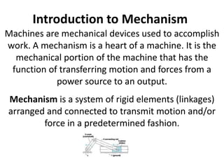
  • 1. Introduction to Mechanism Machines are mechanical devices used to accomplish work. A mechanism is a heart of a machine. It is the mechanical portion of the machine that has the function of transferring motion and forces from a power source to an output. Mechanism is a system of rigid elements (linkages) arranged and connected to transmit motion and/or force in a predetermined fashion. Mechanism consists of linkages and joints.
  • 2. Introduction Vehicle Frame High Rise Building Bridge Supporting Roadway Residential Dwelling Structures can be seen all around us in our everyday lives.
  • 3. Structure or Mechanism? • Can you identify a Structure within this bicycle? • Can you name a mechanisms on this bicycle? Frame = Structure Chain and Sprocket = One example of a mechanism
  • 4. Introduction Machinery is a central part of life today. How many can you identify? Drill Tractor Car Luas Exercise Bicycle
  • 5. Introduction Rack and Pinion Pulley Wheels Cam and Follower All these machines have working parts called – Mechanisms
  • 6. Example of Mechanism Can crusher Simple press Rear-window wiper
  • 7. Example of Mechanisms Moves packages from an assembly bench to a conveyor Lift platform Microwave carrier to assist people on wheelchair
  • 8. Example of Mechanisms Lift platform Front loader Device to close the top flap of boxes
  • 9. 9 Example of Mechanisms Stair climbing mechanism A box that turns itself off Airplane landing gear mechanism
  • 10. Mechanisms and Motion Mechanism A system of moving parts that performs some function. Motion The process of continual change in the position of an object “movement”
  • 11. Motion There are four main types of motion. Linear motion – Train Oscillating Motion – Pendulum of a clock Reciprocating Motion – Hacksaw Rotary Motion - Shaft Pendulum Train Shaft
  • 12. • A kinematic chain is defined as: An assemblage of links and joints, interconnected in a way to provide a controlled output motion in response to a supplied input motion. • A mechanism is defined as: A kinematic chain in which at least one link has been “grounded,” or attached, to the frame of reference (which itself may be in motion). • A machine is defined as: A combination of resistant bodies arranged to compel the mechanical forces of nature to do work accompanied by determinate motions.
  • 13. The similarity between machines and mechanisms is that • They are both combinations of rigid bodies • The relative motion among the rigid bodies are definite.
  • 14. • The difference between machine and mechanism is that machines transform energy to do work, while mechanisms so not necessarily perform this function. • The term machinery generally means machines and mechanisms. The mechanism of its cylinder-link-crank parts is a slider-crank mechanism.
  • 15. Links, kinematic Pair and Chains • A link is defined as a rigid body having two or more pairing elements which connect it to other bodies for the purpose of transmitting force or motion. • A joint of two links having relative motion between them is known as a kinematic pair. • The combination of links and pairs without a fixed link is not a mechanism but a kinematic chain.
  • 16. LINKS • A link, as shown in Figure is an (assumed) rigid body that possesses at least two nodes that are points for attachment to other links. • Binary link - one with two nodes. • Ternary link - one with three nodes. • Quaternary link - one with four nodes.
  • 20. Ken Youssefi Mechanical Engineering Dept. 20 Type of Motion and Mechanisms Translation to Translation Most power sources that are readily available today are either of the pure rotational motion type, such as electric motor or hand crank, or of the pure translational type, such as pneumatic or hydraulic cylinder, or linear actuators.
  • 21. Type of Motion and Mechanisms Rotational to Rotational
  • 22. Type of Motion and Mechanisms Rotation to Translation
  • 23. Classification of kinematic Pairs • According to nature of contact between links. i) Lower Pair ii) Higher pair • According to type of relative motion between the links. i) Sliding Pair ii) Turning Pair iii) Rolling Pair iv) Screw Pair v) Spherical Pair • According to nature of mechanical constraint between two links. i) Closed Pair ii) Unclosed Pair
  • 24. Acc. to the nature of contact 1. Lower pair – When the two links have surface contact between them, it is known as lower pair. 2. Higher pair - When the two links have line or point contact between them, it is known as lower pair. Acc. to nature of relative motion 1. Sliding pair – When one link slides relative to another link, it is known as sliding pair. 2. Turning pair – When one link turns or revolve relative to another link, it is known as turning pair 3. Rolling pair – When one link rolls over the other pair, it is known as rolling pair. 4. Screw pair – If two pairs have turning as well as rolling motion between them, it is known as screw pair. 5. Spherical pair – When a spherical link turns inside a fixed link, it is known as spherical pair. Acc. to nature of constraint 1. Self closed pair – When the two links are joined together mechanically, it is known as self closed pair. 2. Unclosed pair – When the two links are connected either due to gravity or by some external forces, it is known as unclosed pair.
  • 25. Lower Pair A kinematic pair is said to be a lower pair if the links in the pair have surface or area contact between them. Along with a cylinder, a piston forms a lower pair
  • 26. Higher Pair A higher pair is a kinematic pair in which the links have point or line contact. Ball bearings, cam and follower are examples of higher pair. Ball Bearings
  • 27.
  • 28. Sliding Pair As the name suggests, a sliding pair is a kinematic pair in which each element has sliding contact with respect to the other element. Some good examples of sliding pairs are piston inside a cylinder, spur gear drive and square bar in a square hole. Square Bar in a Square Hole – An example of Sliding Pair
  • 29. Rolling Pair In a rolling pair, one element undergoes rolling motion with respect to the other. Wheel rolling on a flat surface – An example of Rolling Pair
  • 30. Turning Pair In a turning pair, one link undergoes turning motion relative to the other link. Example is a shaft with collars in a circular hole.
  • 31. Screw pair A screw pair consists of links that have both turning and sliding motion relative to each other Bolt and Nut – An Example of Screw Pair
  • 32. Cylindrical Pair A cylindrical pair is a kinematic pair in which the links undergo both rotational and translational motion relative to one another.
  • 33. Spherical Pair In a spherical pair, a spherical link turns inside a fixed link.
  • 34. Completely constrained motion Completely constrained motion is a type of constrained motion in which relative motion between the links of a kinematic pair occurs in a definite direction by itself, irrespective of the external forces applied. Square bar in a square hole undergoes completely constrained motion.
  • 35. Incompletely constrained motion In incompletely constrained motion, the relative motion between the links depend on the direction of external forces acting on them. A good example of incompletely constrained motion is the motion of a shaft inside a circular hole. Depending on the direction of external forces applied, the shaft may slide or turn (or do both) inside the circular hole. Shaft in a circular hole
  • 36. Partially (or successfully) constrained motion A kinematic pair is said to be partially or successfully constrained if the relative motion between its links occurs in a definite direction, not by itself, but by some other means. A good example of successfully constrained motion is piston reciprocating inside a cylinder in an internal combustion engine. Normally, when a piston is placed in a cylinder, it may undergo reciprocating motion (upward and downward motion) and turning motion, depending on the external forces applied. It is incompletely constrained. However, if the piston is connected to a connecting rod, its motion is successfully constrained i.e., it can only undergo only reciprocating motion inside the cylinder. Here, some other means (i.e., connecting rod) is used for successfully constraining the motion of the piston. A Piston
  • 37.
  • 38. Types of Joints •Binary Joint •Ternary Joint •Quaternary Joint
  • 39. THE GRASHOF CONDITION • The Grashof condition is a very simple relationship that predicts the rotation behavior or rotatability of a fourbar linkage’s inversions based only on the link lengths. • The linkage is Grashof and at least one link will be capable of making a full revolution with respect to the ground plane. This is called a Class I kinematic chain. If the inequality is not true, then the linkage is non-Grashof and no link will be capable of a complete revolution relative to any other link. This is a Class II kinematic chain.
  • 40.
  • 41.
  • 42. THEORY OF MACHINES AND MECHANISMS John J. Uicker, Jr. / Gordon R. Pennock Copyright © 2011 by Oxford University Press, Inc. Figure 1.28 Four inversions of the Grashof chain: (a, b) crank-rocker mechanisms, (c) draglink mechanism, and (d) double-rocker mechanism.
  • 43. • For the Class I case, S + L < P + Q: • Ground either link adjacent to the shortest and you get a crank-rocker, in which the shortest link will fully rotate and the other link pivoted to ground will oscillate. Ground the shortest link and you will get a double- crank, in which both links pivoted to ground make complete revolutions as does the coupler. • Ground the link opposite the shortest and you will get a Grashof double-rocker, in which both links pivoted to ground oscillate and only the coupler makes a full revolution. • For the Class II case, S + L > P + Q: • All inversions will be triple-rockers in which no link can fully rotate. • For the Class III case, S + L = P + Q: