ROTEX Controls Industrial NEMA 4 and NEMA 7 Limit Switch Catalog
•
1 j'aime•2,150 vues

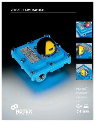
Catalog of ROTEX Controls industrial limit switches used for valve automation and control.

Recommandé
Contenu connexe
Tendances
Tendances (20)
En vedette
En vedette (15)
Similaire à ROTEX Controls Industrial NEMA 4 and NEMA 7 Limit Switch Catalog
Similaire à ROTEX Controls Industrial NEMA 4 and NEMA 7 Limit Switch Catalog (20)
Dernier
Dernier (20)
ROTEX Controls Industrial NEMA 4 and NEMA 7 Limit Switch Catalog
- 1. VERSATILE LIMITSWITCH C O N T R O L S , I N C .
- 2. VERSATILE LIMITSWITCH Series Switch Qty. Switches Conduit Entry 1 2 DXLW Weatherproof DNLF Explosion Proof Entry Threads DXLW DNLF 4R ½” NPT áP 6R ¾” NPT Oá 3M M20X1.5 PP CODE MAKE TYPE 1A Honeywell SPDT Mech, AC/DC, 10A 11A Honeywell SPDT Mech, AC/DC, 15A 2A P & F Prox - IS, DC, 8mA 12A P & F Prox - IS, DC, 100mA 22A P & F Prox - Non IS, DC, 100mA, LED 32A P & F Prox - Non IS, DC,100mA 42A P & F Prox - Non IS, AC, 200mA 2C Ifm Prox - IS, DC, 8 mA 12C Ifm Prox - Non IS, DC,150mA, LED 3A P & F Prox - IS, DC, 3 mA 13A P & F Prox - Non IS, DC, 100mA 3C Ifm Prox - Non IS, DC, 200mA 13C Ifm Prox - IS, DC, 8mA 23C Ifm Prox - Non IS, AC/DC, 100 mA 5A Honeywell DPDT Mech, AC/DC, 10A 15A Honeywell DPDT Mech, AC/DC, 15A 5B Cherry DPDT Mech, AC/DC, 5A 15B Cherry DPDT Mech, AC/DC, 15A 6A Hermitic Sealed Prox, AC/DC, 2A 16A Hermitic Sealed Prox, AC/DC, 2A Body/Cover Bracket Certificates B Aluminum-Black Y Aluminum- Yellow L Aluminum- Blue B5 CF8M Stainless Steel U CU , UL L L C CE A ATEX CM CMRI CC CMRI CCOE BKS1 SS 80 X 30 X 20mm BKC1 CS 80 X 30 X 20mm BKS2 SS 80 X 30 X 30mm BKC2 CS 80 X 30 X 30mm BKS3 SS 130 X 30 X 30mm BKC3 CS 130 X 30 X 30mm BKS4 SS 130 X 30 X 50mm BKC4 CS 130 X 30 X 50mm Standard Stock Items Limit Switch Ordering Code Options 1 Specifications are subject to change without notice
- 3. VERSATILE LIMITSWITCH Bracket for Rotex Actuator models ECV50 through ECV175 Bracket for Rotex Actuator models ECV200 through ECV350 Mounting Bracket Ordering Code Options Brackets are supplied with fasteners for top and bottom, to fit standard actuator ISO threads. ISO-1 30mm X 80mm X 20mm CODE BRACKET MATERIAL BKS1 304 SS BKC1 STEEL, Powder Coated ISO-2 30mm X 80mm X 30mm CODE BRACKET MATERIAL BKS2 304 SS BKC2 STEEL, Powder Coated ISO-3 30mm X 130mm X 30mm CODE BRACKET MATERIAL BKS3 304 SS BKC3 STEEL, Powder Coated ISO-4 30mm X 130mm X 50mm CODE BRACKET MATERIAL BKS4 304 SS BKC4 STEEL, Powder Coated 57SQ 35.4SQ. Ø6 HOLES-4Nos. Ø9 HOLES-4Nos. 110 80 20 45 3 Ø6 110 3 45 55 10 80 Ø6 30 160 30 3 45 55 10 130 Ø6 160 130 Ø6 30 75 3 30 45 Specifications are subject to change without notice 2
- 4. VERSATILE LIMITSWITCH DNLF - Explosion Proof Switch Boxes To Enhance The Performance Of Valve Automation Systems NEMA 4, 4X, 7 & 9 CLASS I, GROUP C & D, CLASS II, GROUP E, F & G, DIVISION 1 & 2 FEATURES • Stainless Steel CF8M housing • Shatterproof Polycarbonate Dome • Easily settable colour coded cam • The locked Serrated cams, ensures the secured settings against any vibration • The switch box confirms to Ex d IIC, T6 Highest level of safety • Cable entry M20, 1/2” NPT or 3/4” NPT • A special PCB, eliminates all the wiring from the switch element to the terminals. Complete protection against short circuit. • All fasteners in stainless steel • Additional mounting hole is threaded as per the UNC series • ATEX, certified by Baseefa United Kingdom Certification no. Baseefa09ATEX0126 • UL Certified confirms to file no. Ul1203 and UL508, File no. 246615 • Temperature range -20 °C to +80 °C On request -40 °C to +80 °C, -60 °C to +80 °C, -20 °C to +120 °C • Cable entry Dual cable entry Optional 4 cable entry • IP 67 : Water, Rain and Dust Proof • IP 68 : Upto 100m on request EC94/9 Ex d, IIC, T6 EN/IS/IEC 60079-0, EN/IS/IEC 60079-1 DOME Unique “two piece” dome arrangement. The black plastic makes the transparent dome an integral part. This ensure an extra long life 3 Way dome Standard dome Only segment is transperent 90° 270° rest all is black 3 Specifications are subject to change without notice
- 5. VERSATILE LIMITSWITCH DXLW1-Weather Proof SPDT Mechanical Switch FEATURES • Aluminum die cast enclosure, powder coated for superior corrosion resistance • Weather proof enclosure to IP67 • Enclosure Certified by UL to UL508, File No. E249752 • Poly carbonate Dome, Shatterproof • Red and Yellow Indicator • Color coded cams easy to identify, and easy to set • Serrated cams locked together ensures adjusted settings secured against any vibration • Special circuit board eliminates internal wiring • Circuit board laminated for complete corrosion protection • Solenoid termination inside the switch box is standard • Three conduit entries provided as standard • Conduit entry options : ½” NPT, M20X1.5 • Complies to Namur mounting standard • Temperature range 4°F to 146°F • Bracket available as option Series Switch Qty. Switches Conduit Entry 4R ½” NPT 3M M20X1.5 Bracket Certificates U CU , UL L L C CE Body/Cover B Aluminum-Black Y Yellow L Blue B5 CF8M Stainless Steel Refer to Bracket Selection Page CODE MAKE MODEL RATING 1A Honeywell V5C010EN3D 10Amp 120 or 250 VAC, 220 VDC 50Hz/60Hz, NO/NC 11A Honeywell V7 1C17E9 201 15Amp 120 or 250 VAC, 220 VDC 50Hz/60Hz, NO/NC Aluminum- Aluminum- Specifications are subject to change without notice 4 ORDERING OPTIONS DXLW ORDERING EXAMPLE 1 2 • DXLW-1A2-4R-B-BKS1-U • Weather proof switch box provided with (2) Honeywell 10 Amp switches, ½” NPT conduit entry, black enclosure. With stainless steel bracket suitable for 80X30 tapping and for 20mm pinion, UL approved.
- 6. VERSATILE LIMITSWITCH DXLW1-Weather Proof SPDT Mechanical Switch MATERIAL OF CONSTRUCTION Valve open BOTTOM Yellow cam SWITCH Valve closed TOP Red cam SWITCH P N GND SOLENOID VALVE ‘X’-½” 5 Specifications are subject to change without notice P N 13 GND SOLENOID CONTROL SIGNAL COM NO NC COM NO NC COM NO NC COM NO NC 10 9 19 6 2 15 4 11 831 17 14 5 12 20 7 16 18 4 136.5 29 4 A/F4 Ø12 5/16UNC-4NOS. SQ.57 M6-4NOS. SQ.35.4 120 105 DIMENSION NPT M20X1.5 X CROSS SECTION 20 COVER FOR MICROSWITCH 1 POLYAMIDE 19 ‘O’RING 1 NBR 18 CIRCUIT BOARD 1 - 17 ‘O’RING 1 NBR 16 PAD 1 POLYAMIDE 15 SPRING 1 STAINLESS STEEL 14 ‘E’ TYPE CIRCLIP 1 SPRING STEEL 13 NON FALLING SCREW 4 STAINLESS STEEL 12 SCREW FOR MICROSWITCH 2 STAINLESS STEEL 11 GASKET 1 NBR 10 INDICATOR COVER 1 POLYCARBONATE 9 INDICATOR 1 ABS PLASTIC 8 THREE WAY TERMINAL BLOCK 4 - 7 MICROSWITCH (SPDT) 2 HONEYWELL/CHERRY 6 SPRING DOWEL 2 SPRING STEEL 5 SHAFT 1 STAINLESS STEEL 4 CAM-LOCK 2 DELRIN 3 CAM 2 POLYCARBONATE 2 COVER 1 ALUMINUM ALLOY LM-6 1 HOUSING 1 ALUMINUM ALLOY LM-6 S.NO. DESCRIPTION QTY. MATERIAL DIMENSION DETAILS WIRING DIAGRAM
- 7. VERSATILE LIMITSWITCH DXLW2-Weather Proof Cylindrical Prox Switch With Option for Intrinsically Safe Switch FEATURES • Intrinsically safe • Cylindrical inductive proximity sensors (EExia) • Aluminum die cast enclosure, powder coated for superior corrosion resistance • Weather proof enclosure to IP67 • Switch box conforms to UL50S,UL File No. E249752 • Polycarbonate Dome, Shatterproof • Red and Yellow Indicator • Color coded cams easy to identify, and easy to set • Solenoid termination inside the switch box is standard • Serrated cams locked together ensures adjusted settings secured against any vibration • Three conduit entries provided as standard • Conduit entry options: ½” NPT, M20X1.5 • Complies to Namur mounting standard • Temperature range 4°F to 146°F • Bracket available as option Series Switch Qty. Switches Conduit Entry Body/Cover B Aluminum-Black Y Yellow L Blue B5 CF8M Stainless Steel Specifications are subject to change without notice 6 ORDERING OPTIONS ORDERING EXAMPLE • DXLW-12A2-4R-B-BKS1 U • UL approved, Weather proof box provided with (2) PEPPERL+FUCHS switches, DC output, each with one NO, ½” NPT conduit entries, black enclosure. With Stainless Steel bracket suitable for 80X30 tapping and for 20mm pinion height. 1 2 4R ½” NPT 3M M20X1.5 Certificates U CU , UL L L C CE Bracket Refer to Bracket Selection Page DXLW CODE MAKE MODEL RATING 2A P & F NJ2 12 GMN 8 VDC, NC 12A P & F NCB2 12GMN35 NO 8V, 24V, 100 mA, NO IS 22A P & F NBN4 12GMN40 Z0 6V-24V, 100 mA, NO IS 32A P & F NCN4 12GMN35 NO 8 VDC, NC 42A P & F NJ4 12GM50 WO 220VAC 200mA 50/60Hz, NC 2C Ifm NF 5003 8 VDC, NC IS 12C Ifm IF 5718 24VDC, 150mA, NO/NC Aluminum- Aluminum-
- 8. VERSATILE LIMITSWITCH DXLW2-Weather Proof Cylindrical Prox Switch MATERIAL OF CONSTRUCTION 16 CROSS SECTION 1 3 DIMENSION DETAILS WIRING DIAGRAM 2 WIRE PROXIMITY-NO P N P N 9 SOLENOID VALVE SOLENOID 2 WIRE PROXIMITY-NC P N GND SOLENOID VALVE HAZARDOUS AREA I 7 Specifications are subject to change without notice P N GND CONTROL SIGNAL NO SOLENOID SIGNAL CONTROL GND GND NO I BU - BN + COM NO NC COM NO NC BU - BN + I Valve open BOTTOM Yellow cam SWITCH Valve closed TOP Red cam SWITCH 4 136.5 29 4 A/F4 Ø12 5/16UNC-4NOS. M6-4NOS. X 105 SQ.35.4 120 DIMENSION ‘X’-½” NPT M20X1.5 SQ.57 10 6 2 15 4 11 8 17 14 5 13 7 18 12 20 COVER FOR MICROSWITCH 1 POLYAMIDE 19 ‘O’RING 1 NBR 18 CIRCUIT BOARD 1 - 17 ‘O’RING 1 NBR 16 PAD 1 POLYAMIDE 15 SPRING 1 STAINLESS STEEL 14 ‘E’ TYPE CIRCLIP 1 SPRING STEEL 13 NON FALLING SCREW 4 STAINLESS STEEL 12 SCREW FOR MICROSWITCH 2 STAINLESS STEEL 11 GASKET 1 NBR 10 INDICATOR COVER 1 POLYCARBONATE 9 INDICATOR 1 ABS PLASTIC 8 THREE WAY TERMINAL BLOCK 4 - 7 PROXIMITY SENSOR 2 P & F, iFM 6 SPRING DOWEL 2 SPRING STEEL 5 SHAFT 1 STAINLESS STEEL 4 CAM-LOCK 2 DELRIN 3 CAM 2 POLYCARBONATE 2 COVER 1 ALUMINUM ALLOY LM-6 1 HOUSING 1 ALUMINUM ALLOY LM-6 S.NO. DESCRIPTION QTY. MATERIAL BU - BN + BU - BN + SAFE AREA POWER SUPPLY NC COM NO NC COM NO NOT IN ROTEX SCOPE Ex ia BARRIER Valve open BOTTOM Yellow cam SWITCH Valve closed TOP Red cam SWITCH NC BU - BN + NC BU - I BN + COM NO NC COM NO NC
- 9. VERSATILE LIMITSWITCH DXLW3-Weather Proof Flat Type Prox Switch With Option for Intrinsically Safe Switch • Intrinsically safe • Flat type inductive proximity sensors (EExia) • Aluminum die cast enclosure, powder coated for superior corrosion resistance • Weather proof enclosure to IP67 • Enclosure Certified by UL to UL50S, UL File No. E249752 • Polycarbonate Dome, Shatterproof • Red and Yellow Indicator • Color coded cams easy to identify, and easy to set • Serrated cams locked together ensures adjusted settings secured against any vibration • Special circuit board eliminates internal wiring • Circuit board laminated for complete corrosion protection • Solenoid termination inside the switch box is standard • Three conduit entries provided as standard • Conduit entry options: ½” NPT, M20X1.5 • Complies to Namur mounting standard • Temperature range 4°F to 146°F • Bracket available as option Series Switch Qty. Switches Conduit Entry 1 2 4R ½” NPT 3M M20X1.5 Body/Cover Aluminum- Aluminum- CODE MAKE MODEL RATING 3A P & F 13A P & F 3C Ifm 13C Ifm 8 VDC, NO/NC IS 23C Ifm Specifications are subject to change without notice 8 FEATURES ORDERING OPTIONS ORDERING EXAMPLE • DXLW-13A2-4RY-BKS1-U • UL approved, Weather proof box provided with (2) PEPPERL+FUCHS flat switches, DC output, each with one NO, ½” NPT conduit entries, yellow enclosure. With Stainless Steel bracket suitable for 80X30 tapping and for 20mm pinion height. NJ2 V3N 8 VDC, 3mA, NC IS NBB3 V3 Z4 10-60VDC, 100mA, NO IS 5026 24V, 200 mA, NO/NC NS 5002 IN 0073 24VDC, 150mA, NO/NC Certificates U CU , UL L L C CE Bracket Refer to Bracket Selection Page DXLW B Aluminum-Black Y Yellow L Blue B5 CF8M Stainless Steel
- 10. VERSATILE LIMITSWITCH DXLW3-Weather Proof Flat Type Prox Switch MATERIALS OF CONSTRUCTION CROSS SECTION 2 STAINLESS STEEL 22 PHILIPS HEAD SCREW 21 CAP FOR SENSOR 2 STAINLESS STEEL 20 COVER FOR MICROSWITCH 1 POLYAMIDE 19 ‘O’RING 1 NBR 18 CIRCUIT BOARD 1 - 17 ‘O’RING 2 NBR 16 PAD 1 POLYAMIDE 15 SPRING 1 STAINLESS STEEL 14 ‘E’ TYPE CIRCLIP 1 SPRING STEEL 13 NON FALLING SCREW 2 STAINLESS STEEL 12 SCREW FOR MICROSWITCH 2 STAINLESS STEEL 11 GASKET 1 NBR 10 INDICATOR COVER 1 POLYCARBONATE 9 INDICATOR 1 ABS PLASTIC 8 THREE WAY TERMINAL BLOCK 2 - 7 PROXIMITY SENSOR 2 P & F, iFM 6 SPRING DOWEL 2 SPRING STEEL 5 SHAFT 1 STAINLESS STEEL 4 CAM-LOCK 2 DELRIN 3 CAM 2 POLYCARBONATE 2 COVER 1 ALUMINUM ALLOY LM-6 1 HOUSING 1 ALUMINUM ALLOY LM-6 S.NO. DESCRIPTION QTY. MATERIAL 20 DIMENSION DETAILS WIRING DIAGRAM 2 WIRE PROXIMITY-NO P N GND 10 HAZARDOUS AREA I 9 Specifications are subject to change without notice P N P N 13 15 8 SOLENOID VALVE SOLENOID CONTROL SIGNAL GND GND 2 WIRE PROXIMITY-NC SOLENOID VALVE BU - BN + P N GND NO I NO SOLENOID CONTROL SIGNAL COM NO NC COM NO NC BU - BN + I Valve open BOTTOM Yellow cam SWITCH Valve closed TOP Red cam SWITCH NC BU - BN + NC BU - I BN + COM NO NC COM NO NC BU - BN + BU - BN + SAFE AREA POWER SUPPLY NC COM NO NC COM NO NOT IN ROTEX SCOPE Ex ia BARRIER Valve open BOTTOM Yellow cam SWITCH Valve closed TOP Red cam SWITCH 9 19 12 2 11 16 6 7 21 3 4 17 1 14 5 18 136.5 29 4 4 Ø12 A/F4 5/16UNC-4NOS. M6-4NOS. X 105 SQ.35.4 120 DIMENSION ‘X’-½” NPT M20X1.5 SQ.57
- 11. VERSATILE LIMITSWITCH DNLF1-Explosion Proof SPDT Mechanical Switch FEATURES • Explosion proof to l, IIA, IIB, and IIC • Enclosure Certified by UL to UL 1203 and UL 508, File No. E246615 • Switch Box conforms to Ex D IIC, T6 highest level of safety • ATEX Certified by CESI, Italy, Certification No. CESI 05 ATEX017 • Aluminum die cast enclosure, powder coated for superior corrosion resistance • Weather proof enclosure to lP67 • Polycarbonate Dome, Shatterproof • Red and Yellow Indicator • Color coded cams easy to identify, and easy to set • Serrated cams locked together ensures adjusted settings secured against any vibration • Special circuit board eliminates internal wiring • Circuit board laminated for complete corrosion protection • Solenoid termination inside the switch box is standard • Two conduit entries provided as standard • Conduit entry options: ½” NPT, ¾” NPT, M20X1.5 • Complies to Namur mounting standard • Temperature range 4°F to 146°F • Bracket available as option ORDERING OPTIONS Body/Cover Series Switch Qty. Switches Conduit Entry Bracket • DNLF-1A2-6R-B-BKS1-U • Explosion proof to I, II A and II B and Weather proof box provided with Honeywell 15 Amps switches 2 nos, each with one NO and one NC, 3/4” NPT cable gland entry. With Stainless Steel bracket, 80X30 tapping, 20mm pinion height, UL approved. Specifications are subject to change without notice 10 ORDERING EXAMPLE 1 2 Refer to Bracket Selection Page Certificates DNLF 4R ½” NPT 6R ¾” NPT 3M M20X1.5 CODE MAKE MODEL RATING 1A Honeywell V5C010EN3D 10Amp 120 or 250 VAC, 220 VDC 50Hz/60Hz, NO/NC 11A Honeywell V7 1C17E9 201 15Amp 120 or 250 VAC, 220 VDC 50Hz/60Hz, NO/NC 1B Cherry D43 CQ1 RA 5Amp 125 or 250 VAC, 220 VDC NO/NC 11B Cherry D45 CQ1 RA 15Amp 125 or 250 VAC, 220 VDC NO/NC U CU , UL L L C CE A ATEX CM CMRI CC CMRI CCDE B Aluminum-Black Y Aluminum- Yellow L Aluminum- Blue B5 CF8M Stainless Steel
- 12. VERSATILE LIMITSWITCH DNLF1-Explosion Proof SPDT Mechanical Switch MATERIAL OF CONSTRUCTION CROSS SECTION ‘O’RING 1 NBR 5/16” UNC 4 NOS. 11 Specifications are subject to change without notice P N GND 10 SOLENOID VALVE P N GND 11 SOLENOID CONTROL SIGNAL COM NO NC COM NO NC COM NO NC COM NO NC Valve open BOTTOM Yellow cam SWITCH Valve closed TOP Red cam SWITCH 154 29 4 Ø12 59 96 155 SQ.57 SQ.35.4 148 M6-4 NOS. ½” NPT or ¾” NPT or M20 X 1.5 3 22 21 14 7 16 17 19 18 15 13 8 1 20 6 4 2 9 5 12 22 21 PHILIPS HEAD SCREW 4 STAINLESS STEEL 20 SCREW FOR EARTHING 2 STAINLESS STEEL 19 CIRCUIT BOARD 1 - 18 ‘O’RING 2 NBR 17 PAD 1 POLYAMIDE 16 SPRING 1 STAINLESS STEEL 15 ‘E’ TYPE CIRCLIP 1 SPRING STEEL 14 SCREW FOR COVER 8 STAINLESS STEEL 13 SCREW FOR CONN. STRIP 2 STAINLESS STEEL 12 SCREW FOR MICROSWITCH 2 STAINLESS STEEL 11 GASKET 1 NBR 10 INDICATOR COVER 1 POLYCARBONATE 9 INDICATOR 1 ABS PLASTIC 8 CONNECTOR STRIP-6WAY 1 POLYMIDE 7 MICROSWITCH (SPDT) 2 HONEYWELL/CHERRY 6 SPRING DOWEL 2 SPRING STEEL 5 SHAFT 1 STAINLESS STEEL 4 CAM-LOCK 2 POM 3 CAM 2 POLYCAMIDE 2 COVER 1 ALUMINUM ALLOY LM-6 1 HOUSING 1 ALUMINUM ALLOY LM-6 S.NO. DESCRIPTION QTY. MATERIAL DIMENSION DETAILS WIRING DIAGRAM DIMENSION ‘X’ OPTIONS : ½” NPT ¾” NPT M20X1.5
- 13. VERSATILE LIMITSWITCH DNLF2-Explosion Proof Cylindrical Prox Switch With Option for Intrinsically Safe Switch • Intrinsically safe • Cylindrical inductive proximity sensors (Eexia) • Aluminum die cast enclosure, powder coated for superior corrosion resistance • Weather proof enclosure to IP67 • Switch box conforms to Ex d llC, T6 highest level of safety • Explosion proof to l, IIA, IIB , and IIC • ATEX certified by CESI, ltaly, Certification No. CESI 05 ATEX017 • ATEX as per EN 60079 • UL Certified, conforms to UL 1203 & UL 508, File No. 246615 • Polycarbonate Dome, Shatterproof • Red and Yellow Indicator • Color coded cams easy to identify, and easy to set • Solenoid termination inside the switch box is standard • Serrated cams locked together ensures adjusted settings secured against any vibration • Two conduit entries provided as standard • Conduit entry options ½” NPT, ¾” NPT, M20X1.5 • Temperature range 4°F to 146°F • Bracket available as option Body/Cover Series Switch Qty. Switches Conduit Entry Bracket U CU , UL L L C CE A ATEX CM CMRI CC CMRI CCDE B Aluminum-Black Y Yellow L Blue B5 CF8M Stainless Steel Refer to Bracket Selection Page Certificates DNLF 4R ½” NPT 6R ¾” NPT 3M M20X1.5 Aluminum- Aluminum- CODE MAKE MODEL RATING 2A P & F NJ2 12 GMN 8 VDC, NC IS 12A P & F NCB2 12GMN35 NO 8V, 24V, 100 mA, NO IS 22A P & F NBN4 12GMN40 Z0 6V-24V, 100 mA, NO 32A P & F NCN4 12GMN35 NO 8V, 24V, 100mA, NC 42A P & F NJ4 12GM50 WO 220VAC 200mA 50/60Hz, NC 2C Ifm NF 5003 8 VDC, NC IS 12C Ifm IF 5718 24VED, 150mA, NO/NC Specifications are subject to change without notice 12 FEATURES ORDERING OPTIONS ORDERING EXAMPLE 1 2 • DNLF-12A2-4R-BU • UL approved, Explosion proof box with (2) PEPPERL +FUCHS switches, DC output, ½” NPT conduit entry, black enclosure.
- 14. VERSATILE LIMITSWITCH DNLF2-Explosion Proof Cylindrical Prox Switch MATERIAL OF CONSTRUCTION CROSS SECTION PHILIPS HEAD SCREW 4 STAINLESS STEEL 21 20 NON FALLING SCREW 8 STAINLESS STEEL 19 ‘O’RING 1 NBR 18 ‘O’RING 2 NBR 17 BRACKET 1 M.S. 16 SPRING 1 STAINLESS STEEL 15 ‘E’ TYPE CIRCLIP 1 SPRING STEEL 14 SCREW FOR EARTHING 2 STAINLESS STEEL 13 SCREW FOR CONN. STRIP 2 STAINLESS STEEL 12 SCREW FOR BRACKET 2 STAINLESS STEEL 11 GASKET 1 NBR 10 INDICATOR COVER 1 POLYCARBONATE 9 INDICATOR 1 ABS PLASTIC 8 TERMINAL BLOCK-6WAY 1 - 7 PROXIMITY SENSOR 2 P&F, iFM 6 SPRING DOWEL 2 SPRING STEEL 5 SHAFT 1 STAINLESS STEEL 4 CAM-LOCK 2 DELRIN 3 CAM 2 POLYCARBONATE 2 COVER 1 ALUMINUM ALLOY LM-6 1 HOUSING 1 ALUMINUM ALLOY LM-6 S.NO. DESCRIPTION QTY. MATERIAL 19 20 1 8 DIMENSION DETAILS WIRING DIAGRAM 2 WIRE PROXIMITY-NC P N GND P N SOLENOID VALVE HAZARDOUS AREA I 13 Specifications are subject to change without notice P N GND P N NO SOLENOID CONTROL SIGNAL 2 WIRE PROXIMITY-NO SOLENOID VALVE SOLENOID CONTROL SIGNAL GND GND NO I BU - BN + COM NO NC COM NO NC BU - BN + I Valve open BOTTOM Yellow cam SWITCH Valve closed TOP Red cam SWITCH NC BU - BN + NC BU - I BN + COM NO NC COM NO NC BU - BN + BU - BN + SAFE AREA POWER SUPPLY NC COM NO NC COM NO NOT IN ROTEX SCOPE Ex ia BARRIER Valve open BOTTOM Yellow cam SWITCH Valve closed TOP Red cam SWITCH 154 29 4 59 155 96 Ø12 ½” NPT or ¾” NPT or M20 X 1.5 SQ.57 5/16”UNC 4 NOS. SQ.35.4 148 M6-4 NOS. DIMENSION ‘X’ OPTIONS : ½” NPT ¾” NPT M20X1.5 3 17 12 15 18 13 16 4 14 7 11 6 2 21 10 9 5
- 15. VERSATILE LIMITSWITCH DNLF3-Explosion Proof Flat Prox Switch With Option for Intrinsically Safe Switch • Intrinsically safe • Flat inductive proximity sensors (Eexia) • Aluminum die cast enclosure, powder coated for superior corrosion resistance • Weather proof enclosure to IP67 • Switch box conforms to Ex d llC, T6 highest level of safety • Explosion proof to l, IIA, IIB , and IIC • ATEX certified by CESI, ltaly, Certification No. CESI 05 ATEX017 • ATEX as per EN 60079 • UL Certified, conforms to UL 1203 & UL 508, File No. 246615 • Polycarbonate Dome, Shatterproof • Red and Yellow Indicator • Color coded cams easy to identify, and easy to set • Solenoid termination inside the switch box is standard • Serrated cams locked together ensures adjusted settings secured against any vibration • Two conduit entries provided as standard • Conduit entry options ½” NPT, ¾” NPT, M20X1.5 • Temperature range 4°F to 146°F • Bracket available as option Body/Cover Series Switch Qty. Switches Conduit Entry Bracket U CU , UL L L C CE A ATEX CM CMRI CC CMRI CCDE B Aluminum-Black Y Yellow L Blue B5 CF8M Stainless Steel Refer to Bracket Selection Page Certificates DNLF 4R ½” NPT 6R ¾” NPT 3M M20X1.5 CODE MAKE MODEL RATING 3A P & F NJ2 V3N 8 VDC, 3mA, NC IS 13A P & F NBB3 V3 Z4 10-60VDC, 100mA, NO 3C Ifm IS 5026 24V, 200 mA, NO/NC 13C Ifm NS 5002 8 VDC, NO/NC IS 23C Ifm IN 0073 24VDC, 150mA, NO/NC Aluminum- Aluminum- Specifications are subject to change without notice 14 FEATURES ORDERING OPTIONS ORDERING EXAMPLE 1 2 • DNLF-3A2-4R-BU • UL approved, Explosion proof box with (2) PEPPERL +FUCHS switches, Intrinsicaly safe, ½” NPT conduit entry, black enclosure
- 16. VERSATILE LIMITSWITCH DNLF3-Explosion Proof Flat Prox Switch MATERIAL OF CONSTRUCTION CROSS SECTION 12 2 WIRE PROXIMITY-NO P N P N SOLENOID VALVE SOLENOID 2 WIRE PROXIMITY-NC P N GND SOLENOID VALVE HAZARDOUS AREA I 21 20 NON FALLING SCREW 8 STAINLESS STEEL 19 ‘O’RING 1 NBR 18 ‘O’RING 2 NBR 17 BRACKET 1 M.S. 16 SPRING 1 STAINLESS STEEL 15 ‘E’ TYPE CIRCLIP 1 SPRING STEEL 14 SCREW FOR EARTHING 2 STAINLESS STEEL 13 SCREW FOR CONN. STRIP 2 STAINLESS STEEL 12 SCREW FOR BRACKET 2 STAINLESS STEEL 11 GASKET 1 NBR 10 INDICATOR COVER 1 POLYCARBONATE 9 INDICATOR 1 ABS PLASTIC 8 TERMINAL BLOCK-6WAY 1 - 7 PROXIMITY SENSOR 2 P&F, iFM 6 SPRING DOWEL 2 SPRING STEEL 5 SHAFT 1 STAINLESS STEEL 4 CAM-LOCK 2 DELRIN 3 CAM 2 POLYCARBONATE 2 COVER 1 ALUMINUM ALLOY LM-6 1 HOUSING 1 ALUMINUM ALLOY LM-6 15 Specifications are subject to change without notice P N GND CONTROL SIGNAL NO SOLENOID CONTROL SIGNAL GND GND NO I BU - BN + COM NO NC COM NO NC BU - BN + I Valve open BOTTOM Yellow cam SWITCH Valve closed TOP Red cam SWITCH NC BU - BN + NC BU - I BN + COM NO NC COM NO NC BU - BN + BU - BN + SAFE AREA POWER SUPPLY NC COM NO NC COM NO NOT IN ROTEX SCOPE Ex ia BARRIER Valve open BOTTOM Yellow cam SWITCH Valve closed TOP Red cam SWITCH 154 29 4 59 96 155 ½” NPT ¾” NPT M20 X 1.5 Ø12 SQ.57 5/16” UNC 4 NOS. SQ.35.4 M6-4NOS. 148 PHILIPS HEAD SCREW 4 STAINLESS STEEL S.NO. DESCRIPTION QTY. MATERIAL DIMENSION DETAILS WIRING DIAGRAM DIMENSION ‘X’ OPTIONS : ½” NPT ¾” NPT M20X1.5 22 3 17 5 9 10 21 6 2 11 7 4 16 1 8 13 18 15 19 20 23 14
- 17. VERSATILE LIMITSWITCH DNLF5-Explosion Proof DPDT Mechanical Switch • Explosion proof to l, IIA, IIB, and IIC • Enclosure certified to UL 1203 & UL508, File No. 246615 • Switch Box conforms to Ex D IIC, T6 highest level of safety • ATEX certified by CESI, ltaly, Cert No. CESI 05 ATEX017 • Aluminum die cast enclosure, powder coated for superior corrosion resistance • Weather proof enclosure to lP67 • Polycarbonate Dome, Shatterproof • Red and Yellow Indicator • Color coded cams easy to identify, easy to set • Special circuit board eliminates internal wiring • Circuit board laminated for complete corrosion protection • Solenoid termination inside the switch box not available • Serrated cams locked together ensures adjusted settings secured against any vibration • Two conduit entries provided as standard • Conduit entry options ½” NPT, ¾” NPT, M20X1.5 • Temperature 4°F to 146°F • Bracket available as option Body/Cover Series Switch Qty. Switches Conduit Entry Bracket DNLF 4R ½” NPT 1 2 6R ¾” NPT 3M M20X1.5 CODE MAKE MODEL RATING 5A Honeywell V5C010EN3D 10Amp B Aluminum-Black Y Yellow L Blue B5 CF8M Stainless Steel 120 or 250 VAC, 220 VDC 50Hz/60Hz, NO/NC 15A Honeywell V7 1C17E9 201 15Amp 120 or 250 VAC, 220 VDC 50Hz/60Hz, NO/NC 1B Cherry D43 CQ1 RA 5Amp 125 or 250 VAC, 220 VDC NO/NC 11B Cherry D45 CQ1 RA 15Amp 125 or 250 VAC, 220 VDC NO/NC U CU , UL L L C CE A ATEX CM CMRI CC CMRI CCDE Refer to Bracket Selection Page Certificates Aluminum- Aluminum- Specifications are subject to change without notice 16 FEATURES •• ORDERING OPTIONS ORDERING EXAMPLE DNLF-5A2-6R-B-BKS1-A Explosion proof to I, II A and II B and Weather proof box provided with Honeywell 10 Amp switches 2 nos, each with two NO and two NC, 3/4" NPT cable gland entry. With Stainless Steel bracket suitable for 80X30 tapping and for 20mm pinion height. With ATEX Certification.
- 18. VERSATILE LIMITSWITCH DNLF5-Explosion Proof DPDT Mechanical Switch MATERIAL OF CONSTRUCTION CROSS SECTION PHILIPS HEAD SCREW 4 STAINLESS STEEL 21 20 SCREW FOR EARTHING 2 STAINLESS STEEL 19 CIRCUIT BOARD 1 - 18 ‘O’RING 2 NBR 17 ‘O’RING 1 NBR 16 SPRING 1 STAINLESS STEEL 15 ‘E’ TYPE CIRCLIP 1 SPRING STEEL 14 SCREW FOR COVER 8 STAINLESS STEEL 13 SCREW FOR CONN. STRIP 2 STAINLESS STEEL 12 SCREW FOR BRACKET 2 STAINLESS STEEL 11 GASKET 1 NBR 10 INDICATOR COVER 1 POLYCARBONATE 9 INDICATOR 1 ABS PLASTIC 8 CONNECTOR STRIP 6 WAY 1 POLYMIDE 7 MICROSWITCH (DPDT) 2 HONEYWELL/CHERRY 6 SPRING DOWEL 2 SPRING STEEL 5 SHAFT 1 STAINLESS STEEL 4 CAM-LOCK 2 POM 3 CAM 2 POLYMIDE 2 COVER 1 ALUMINUM ALLOY LM-6 1 HOUSING 1 ALUMINUM ALLOY LM-6 S.NO. DESCRIPTION QTY. MATERIAL 12 3 17 21 14 7 19 18 15 Ø12 ½” NPT or ¾” NPT or M20 X 1.5 17 Specifications are subject to change without notice NO NC COM NO NC NO NC NO NC NO NC NO NC COM NO NC COM NO NC COM Valve open BOTTOM Yellow cam SWITCH Valve closed TOP Red cam SWITCH 10 13 8 11 20 1 6 4 2 9 5 16 DIMENSION DETAILS WIRING DIAGRAM 154 29 4 59 96 155 SQ.57 5/16” UNC 4 NOS. SQ.35.4 148 M6-4 NOS. DIMENSION ‘X’ OPTIONS : ½” NPT ¾” NPT M20X1.5
- 19. VERSATILE LIMITSWITCH DNLF6-Explosion Proof Hermetically Sealed Prox Switch ROTEX Cobra Switch • Explosion proof to l, IIA, IIB, and IIC • Enclosure certified to UL 1203 & UL508, File No. 246615 • Switch Box conforms to Ex D IIC, T6 highest level of safety • ATEX certified by CESI, ltaly, Cert No. CESI 05 ATEX017 • Aluminum die cast enclosure, powder coated for superior corrosion resistance • Weather proof enclosure to lP67 • Polycarbonate Dome, Shatterproof • Red and Yellow Indicator • Color coded cams easy to identify, easy to set • Special circuit board eliminates internal wiring • Circuit board laminated for complete corrosion protection • Solenoid termination inside the switch box is standard • Serrated cams locked together ensures adjusted settings secured against any vibration • Two conduit entries provided as standard • Conduit entry options ½” NPT, ¾” NPT, M20X1.5 • Temperature 4°F to 146°F • Bracket available as option Series Switch Qty. Switches Conduit Entry DNLF 4R ½” NPT 1 2 6R ¾” NPT 3M M20X1.5 CODE MAKE MODEL RATING 6A Hermetic Switch Inc. COBRA 2Amps, 220V AC/DC, 50Hz/60Hz, NO/NC Body/Cover B Aluminum-Black Y Yellow L Blue B5 CF8M Stainless Steel Hermetic Switch Inc. COBRA GOLD 0-48 VDC, up to 100mA 0-220 VAC, 20 mA Bracket U CU , UL L L C CE A ATEX Refer to Bracket Selection Page Certificates Aluminum- Aluminum- Specifications are subject to change without notice 18 FEATURES ORDERING OPTIONS •• 16A ORDERING EXAMPLE DNLF-6A2-6R-B-BKS1-A Explosion proof box with (2) hermetically sealed switches, ¾” conduit entries, black enclosure, with stainless steel bracket suitable for 80X30 tapping and for 20mm pinion height. With ATEX certificate
- 20. VERSATILE LIMITSWITCH DNLF6-Explosion Proof Hermetically Sealed Prox Switch ROTEX Cobra Switch MATERIAL OF CONSTRUCTION CROSS SECTION 23 CIRCUIT BOARD 1 - 22 ‘O’RING 1 NBR 21 PHILIPS HEAD SCREW 4 STAINLESS STEEL 20 SCREW FOR EARTHING 2 STAINLESS STEEL 19 MOUNTING PLATE 1 M.S. 18 ‘O’RING 2 NBR 17 CAM INSERT 2 POLYAMIDE 16 SPRING 1 STAINLESS STEEL 15 ‘E’ TYPE CIRCLIP 1 SPRING STEEL 14 NON FALLING SCREW 8 STAINLESS STEEL 13 SCREW FOR CONN. STRIP 2 STAINLESS STEEL 12 SCREW FOR REEDSWITCH 2 STAINLESS STEEL 11 GASKET 1 NBR 10 INDICATOR COVER 1 POLYCARBONATE 9 INDICATOR 1 ABS PLASTIC 8 CONNECTOR STRIP-6WAY 1 POLYMIDE 7 REED SWITCH ASSEMBLY 2 - 6 SPRING DOWEL 2 SPRING STEEL 5 SHAFT 1 STAINLESS STEEL 4 CAM-LOCK 2 POM 3 CAM 2 POLYCAMIDE 2 COVER 1 ALUMINUM ALLOY LM-6 1 HOUSING 1 ALUMINUM ALLOY LM-6 S.NO. DESCRIPTION QTY. MATERIAL 12 15 DIMENSION DETAILS WIRING DIAGRAM P N GND SOLENOID VALVE 3 22 21 14 7 17 19 23 18 19 Specifications are subject to change without notice P N GND SOLENOID CONTROL SIGNAL COM NO NC COM NO NC COM NO NC COM NO NC Valve open BOTTOM Yellow cam SWITCH Valve closed TOP Red cam SWITCH 10 13 8 1 11 20 6 4 2 9 5 16 154 29 4 59 ½” NPT or ¾” NPT or M20 X1.5 Ø12 96 155 SQ.57 5/16” UNC 4 NOS. SQ.35.4 M6-4 NOS. 148 DIMENSION ‘X’ OPTIONS : ½” NPT ¾” NPT M20X1.5
- 21. VERSATILE LIMITSWITCH DNLF-Limit Switch With Integral Solenoid Valve ROTEX STRIKER Switch NEMA 4, 4X, 7 & 9 ORDERING OPTIONS Switch Qty Switches Conduit Entry Body/Cover Coils Voltage Sol. Body S Single D Dual A Aluminum S 316 SS Bracket Certificates MAKE MODEL RATING Honeywell V15S05-CZ100A05-0 15Amp 125 OR 250V AC, Specifications are subject to change without notice 20 •• FEATURES Explosion proof to I, IIA, IIB, and IIC Enclosure certified to UL 1203 & Ul508, File No. 246615 • Switch Box conforms to Ex D IIC, T6 highest level of safety • ATEX certified by CESI, Italy, Cert No. CESI 05 ATEX017 • Aluminum die cast enclosure, powder coated • Weatherproof enclosure to IP67 • Temperature -4 °F to 176 °F • Polycarbonate Dome, Shatterproof, Red/Yellow • Color coded cams easy to identify, easy to set • Serrated cams locked together ensures adjusted settings are secure against any vibration • Two conduit entries provided as standard • Conduit entry options ½” NPT, ¾” NPT (Std), M20X1.5 • Choice of proximity type or mechanical switches • Solenoid coils are mounted INSIDE the box • 4 way solenoid can work for DA or SR actuator • ¼” NPT solenoid body in SS or aluminum, Cv=1.1 • Available single coil or dual coil • Special configurations may be available on request B Aluminum-Black Y Aluminum- Yellow L Aluminum- Blue B5 CF8M Stainless Steel 4R ½” NPT 6R ¾” NPT 3M M20X1.5 Series DNLF 1 2 1 120V AC 2 24V DC Refer to Bracket Selection Page U UL C CE A ATEX CODE 1A 0.1Amp 48V DC, NO/ NC 11A Honeywell V7-1C17E9-201 15Amp 125 OR 250V AC, 0.5Amp 125V DC, 0.25Amp 250V DC, NO/ NC 3A P&F NJ2-V3-N 8V DC, 3mA, NC Type EEx ia 13A (Intrinsically Safe) NBB3-V3-Z4 10-60V DC, 100mA, NO 6A Hermetic Switch Inc. R1 2Amps, 220V AC/ DC 16A R2 0.2Amps, 24V DC •• ORDERING EXAMPLE DNLF-6A26RL-S1A-U Explosion proof aluminum box with (2) Hermetically sealed switches, (2) ¾” conduit entries, blue enclosure with single coil 120 VAC solenoid ¼” aluminum body, UL Certified Consult Rotex Controls with your specific application requirements
- 22. VERSATILE LIMITSWITCH DNLF-Limit Switch For Dribble Control ROTEX STRIKER DRIBBLE Switch NEMA 4, 4X, 7 & 9 Body/Cover FEATURES Explosion proof to I, IIA, IIB, and IIC Switch Qty Switches Conduit Entry Dribble B Aluminum-Black Y Aluminum- Yellow L Aluminum- Blue B5 CF8M Stainless Steel 4R ½” NPT 6R ¾” NPT 3M M20X1.5 MAKE MODEL RATING Honeywell V15S05-CZ100A05-0 15Amp 125 OR 250V AC, Voltage Sol. Body ORDERING EXAMPLE DNLF-1A36RL-DR1A-U 21 Specifications are subject to change without notice Series DNLF 3 4 CODE 1A 0.1Amp 48V DC, NO/ NC 11A Honeywell V7-1C17E9-201 15Amp 125 OR 250V AC, 0.5Amp 125V DC, 0.25Amp 250V DC, NO/ NC 3A P&F NJ2-V3-N 8V DC, 3mA, NC Type EEx ia 13A (Intrinsically Safe) NBB3-V3-Z4 10-60V DC, 100mA, NO 6A Hermetic Switch Inc. R1 2Amps, 220V AC/ DC 16A R2 0.2Amps, 24V DC 1 120V AC 2 24V DC Bracket Certificates A Aluminum S 316 SS U UL C CE A ATEX Refer to Bracket Selection Page DR •• Enclosure certified to UL 1203 & Ul508, File No. 246615 • Switch Box conforms to Ex D IIC, T6 highest level of safety • ATEX certified by CESI, Italy, Cert No. CESI 05 ATEX017 • Aluminum die cast enclosure, powder coated • Weatherproof enclosure to IP67 • Temperature -4 °F to 176 °F • Polycarbonate Dome, Shatterproof, Red/Yellow • Color coded cams easy to identify, easy to set • Serrated cams locked together ensures adjusted settings are secure against any vibration • Two conduit entries provided as standard • Conduit entry options ½” NPT, ¾” NPT (Std), M20X1.5 • Choice of proximity type or mechanical switches • Solenoid coils are mounted INSIDE the box • Dribble configuration allows midway valve position for applications such as tank filling • ¼” NPT solenoid body in SS or aluminum, Cv=1.1 • Special configurations may be available on rquest ORDERING OPTIONS •• Explosion proof aluminum box with (3) mechanical switches, (2) ¾” conduit entries, blue enclosure with 120 VAC dribble control ¼” aluminum body, UL Certified Consult Rotex Controls with your specific application requirements
- 23. VERSATILE LIMITSWITCH DNLF1-P-NEMA 4 SPDT Mechanical Switch with Position Transmitter FEATURES Position transmitter may be added to DNLF1 switches only. Feedback Bracket Certificates U CU , UL L L C CE Honeywell V5C010EN3D 10Amp Body/Cover Specifications are subject to change without notice 22 •• ORDERING OPTIONS Series Switch Qty Switches DNLF-1A2-P1-4R-B-BSK1-C Explosion proof box having a potentiometer output of 1 K ohm resistance when rotated 90 degree. The switch has a 10 amp Honeywell micro switch, with ½” cable entries, Black color, Stainless Steel Bracket 80x30 tapping, pinion height 20 mm, CE approved. •• Limit Switch with position feedback rated NEMA 4, 4X • 0.2% FS - Repeatability 0.2% FS • Hysterisis 0.3% FS • Field adjustable Feedback, 1 K or 10 K Ohms • Two conduit entries provided as standard • Conduit entry options : ½” NPT, ¾” NPT, M20X1.5 • Complies to Namur mounting standard • 2 wire system • Spring loaded resistive feedback • Microswitch feedback for on and off provided • Visual percentage indicator provided • Red and Yellow Indicator • Temperature range 4°F to 146°F • Bracket available as option ORDERING EXAMPLE 4R ½” NPT 6R ¾” NPT 3M M20X1.5 DNLF Conduit Entry 1 2 P1 1 K Ohm P10 10 K Ohm Refer to Bracket Selection Page CODE MAKE MODEL RATING 1A 11A Honeywell V7-1C17E9-201 15Amp 1B Cherry 11B Cherry 120 or 250 VAC, 220 VDC 50Hz/60Hz, NO/NC 120 or 250 VAC, 220 VDC 50Hz/60Hz, NO/NC D43 CQ1 RA 5Amp 125 or 250 VAC, 220 VDC NO/NC D45 CQ1 RA 15Amp 125 or 250 VAC, 220 VDC NO/NC B Aluminum-Black Y Aluminum- Yellow L Aluminum- Blue B5 CF8M Stainless Steel
- 24. VERSATILE LIMITSWITCH DNLF1-P-NEMA 4 SPDT Mechanical Switch with Position Transmitter MATERIAL OF CONSTRUCTION CROSS SECTION 27 HEX SOC. SET SCREW 2 STAINLESS STEEL 26 POTENTIOMETER 1 - 25 PHILIPS HEAD SCREW 4 STAINLESS STEEL 24 CAM-2 1 ALUMINUM 23 CAM-1 1 ALUMINUM 22 BRACKET 1 M.S. 21 SLOTTED CHEESE HEAD SCREW 2 STAINLESS STEEL 20 NON FALLING SCREW 8 STAINLESS STEEL 19 ‘O’RING 1 NBR 18 ‘O’RING 2 NBR 17 PAD 1 POLYAMIDE 16 SPRING 1 STAINLESS STEEL 15 ‘E’ TYPE CIRCLIP 1 SPRING STEEL 14 SCREW FOR EARTHING 2 STAINLESS STEEL 13 SCREW FOR CONN. STRIP 2 STAINLESS STEEL 12 SCREW FOR MICROSWITCH 2 STAINLESS STEEL 11 GASKET 1 NBR 10 INDICATOR COVER 1 POLYCARBONATE 9 INDICATOR 1 ABS PLASTIC 8 TERMINAL BLOCK-6WAY 1 - 7 MICRO SWITCH (SPDT) 2 HONEYWELL/CHERRY 6 SPRING DOWEL 2 SPRING STEEL 5 SHAFT 1 STAINLESS STEEL 4 CAM-LOCK 2 DELRIN 3 CAM 2 POLYCARBONATE 2 COVER 1 ALUMINUM ALLOY LM-6 1 HOUSING 1 ALUMINUM ALLOY LM-6 S.NO. DESCRIPTION QTY. MATERIAL DNLF 1A2+P1 WITH MICROSWITCH DIMENSION DETAILS WIRING DIAGRAM 154 29 4 Ø12 ½” NPT or ¾” NPT or M20 X 1.5 59 96 155 SQ.57 5/16” UNC 4 NOS. SQ.35.4 148 M6-4 NOS. 3 22 21 14 7 16 17 19 18 15 P N GND 23 Specifications are subject to change without notice 10 13 8 1 11 20 6 4 2 9 5 12 SOLENOID VALVE P N GND SOLENOID CONTROL SIGNAL COM NO NC COM NO NC COM NO NC COM NO NC Valve open BOTTOM Yellow cam SWITCH Valve closed TOP Red cam SWITCH DIMENSION ‘X’ OPTIONS : ½” NPT ¾” NPT M20X1.5
- 25. VERSATILE LIMITSWITCH DXLW-AF Weather Proof Limit Switch AS-I Protocol DXLW-AFD-Weather Proof Limit Switch-AS-I Protocol, Dribble control • Weather proof type “W” limit switch box has been designed to overcome lengthy wiring. It is easy to operate, maintain and control. • The limit switch box is configured to exchange data through field bus using AS-I protocol. • Field bus connectivity is achieved by using one or two cables depending on wiring system. • Solenoid termination inside enclosure is standard. COMMUNICATION CHARACTERISTICS Protocol : AS-I Interface using V2.1 profile 4140 simple addressing Transmission : AS-I cable flat type 2 wire, need 2 pair, or 5 wire cable Bus Structure : Line or tree using repeaters Max # of Slaves : 31 Input/output per Box : 2 Outputs / 2 Inputs Bus Cable Length : 100m, 300m with repeaters Field Communication : Hand held infra-red controller ELECTRICAL CHARACTERISTICS Supply Voltage : 24 V DC +/- 10% with max 15% ripple Bus Consumption : <250 mA Solenoid Consumption : Up to 8 Watts Protection : IP 55 Supply Connection (24V) : Flat with vampire type connector Ground Connection : Ground screw inside enclosure Electromagnetic Compatibility : CE, Directive EMC 89/336/EEC Body/Cover ORDERING OPTIONS Series Switch Qty. Switches Conduit Entry Protocol Certificates B Aluminum-Black Y Aluminum- Yellow L Aluminum- Blue B5 CF8M Stainless Steel 4R ½” NPT 3M M20X1.5 CODE MAKE MODEL RATING 1A Honeywell 3A P & F 13A P & F V5SC010EN3D 24 VDC, 5Amp NJ2 V3N 8 VDC, 3mA, NC IS NBB3 V3 Z4 10-60VDC, 100mA, NO Specifications are subject to change without notice 24 1 2 AF AS-I AFD AS-I Dribble C CE Bracket Refer to Bracket Selection Page DXLW •• ORDERING EXAMPLE DXLW-13A2-4R-B-AF Weather proof box provided with (2) PEPPERL+FUCHS flat switches, DC output, each with one NO, ½” NPT conduit entries, black enclosure. With AS-I Protocol.
- 26. VERSATILE LIMITSWITCH DNLF-AF Explosion Proof Limit Switch AS-I Protocol DNLF-AFD-Explosion Proof Limit Switch-AS-I Protocol, Dribble control • Explosion proof type 'F' limit switch box has been designed to overcome lengthy wiring. It is easy to operate, maintain and control. • The limit switch box is configured to exchange data through field bus using AS-I protocol. • Field bus connectivity is achieved by using one or two cables depending on wiring system. • Solenoid termination inside enclosure is standard. COMMUNICATION CHARACTERISTICS Protocol : AS-I Interface using V2.1 profile 4140 simple addressing Transmission : AS-I cable flat type 2 wire, need 2 pair, or 5 wire cable Bus Structure : Line or tree using repeaters Max # of Slaves : 31 Input/output per Box : 2 Outputs / 2 Inputs Bus Cable Length : 100m, 300m with repeaters Field Communication : Hand held infra-red controller ELECTRICAL CHARACTERISTICS Supply Voltage : 24 V DC +/- 10% with max 15% ripple Bus Consumption : <250 mA Solenoid Consumption : Up to 8 Watts Protection : IP 55 Supply Connection (24V) : Flat with vampire type connector Ground Connection : Ground screw on enclosure exterior Electromagnetic Compatibility : CE, Directive EMC 89/336/EEC Body/Cover ORDERING OPTIONS Series Switch Qty. Switches Conduit Entry Protocol Certificates B Aluminum-Black Y Aluminum- Yellow L Aluminum- Blue B5 CF8M Stainless Steel 4R ½” NPT 6R ¾” NPT 3M M20X1.5 1 2 CODE MAKE MODEL RATING 1A Honeywell 3A P & F 13A P & F V5SC010EN3D 24 VDC, 5Amp NJ2 V3N 8 VDC, 3mA, NC IS NBB3 V3 Z4 10-60VDC, 100mA, NO ORDERING EXAMPLE 25 Specifications are subject to change without notice AF AS-I AFD AS-I Dribble CM CMRI CC CMRI CCOE C CE Bracket Refer to Bracket Selection Page DNLF •• DNLF-13A2-4R-Y-AF Explosion proof box provided with (2) PEPPERL+FUCHS flat switches, DC output, each with one NO, ½” NPT conduit entries, yellow enclosure. With AS-I Protocol.
- 27. VERSATILE LIMITSWITCH DXLW-DF/ DXLW-CF Weather Proof Limit Switch DEVICENET or CAN OPEN Protocol • Weather proof type ‘W’ limit switch box has been designed to overcome lengthy wiring. It is easy to operate, maintain and control. • The limit switch box is configured to exchange data through field bus using either DEVICENET or CAN OPEN protocol. • Field bus connectivity is achieved by using 2X2 cable and grounding, 5 core cable. • Solenoid termination inside enclosure is standard. COMMUNICATION CHARACTERISTICS Protocol : DEVICENET or CAN OPEN Transmission : Shielded and twisted pair 2X2-wire cable Bus Structure : Line or tree using repeaters Max # of Slaves : 63 Input/output per Box : 2 Outputs / 2 Inputs Bus Cable Length : 500m at 125 KBD and 100m at 500 KBd Field Communication : Dip switch on the circuit board Supply Voltage : 24 V DC +/- 10% with max 15% ripple Bus Consumption : <100 mA Solenoid Consumption : Up to 8 Watts Protection : IP 55 Supply Connection (24V) : M8 socket 4 pin male Bus Connection : 5 pin M12-A male Ground Connection : Ground screw inside enclosure Electromagnetic Compatibility : CE, Directive EMC 89/336/EEC Body/Cover ORDERING OPTIONS Series Switch Qty. Switches Conduit Entry Certificates 4R ½” NPT 3M M20X1.5 Specifications are subject to change without notice 26 ELECTRICAL CHARACTERISTICS B Aluminum-Black Y Aluminum- Yellow L Aluminum- Blue B5 CF8M Stainless Steel 1 2 CODE MAKE MODEL RATING 1A Honeywell 3A P & F 13A P & F V5SC010EN3D 24 VDC, 5Amp NJ2 V3N 8 VDC, 3mA, NC IS NBB3 V3 Z4 10-60VDC, 100mA, NO C CE Protocol Bracket DF DEVICENET CF CAN OPEN Refer to Bracket Selection Page DXLW •• ORDERING EXAMPLE DXLW-13A2-4R-Y-DF Weather proof box provided with (2) PEPPERL+FUCHS flat switches, DC output, each with one NO, ½” NPT conduit entries, yellow enclosure. With DEVICENET Protocol.
- 28. VERSATILE LIMITSWITCH DNLF-DF/ DNLF-CF Explosion Proof Limit Switch DEVICENET or CAN OPEN Protocol • Explosion proof type ‘F’ limit switch box has been designed to overcome lengthy wiring. It is easy to operate, maintain and control. • The limit switch box is configured to exchange data through field bus using either DEVICENET or CAN OPEN protocol. • Field bus connectivity is achieved by using 2X2 cable and grounding, 5 core cable. • Solenoid termination inside enclosure is standard. COMMUNICATION CHARACTERISTICS Protocol : DEVICENET or CAN OPEN Transmission : Shielded and twisted pair 2X2-wire cable Bus Structure : Line or tree using repeaters Max # of Slaves : 63 Input/output per Box : 2 Outputs/ 2 Inputs Bus Cable Length : 500m at 125 KBD and 100m at 500 KBd Field Communication : Dip switch on the circuit board ELECTRICAL CHARACTERISTICS Supply Voltage : 24 V DC +/- 10% with max 15% ripple Bus Consumption : <100 mA Solenoid Consumption : Up to 8 Watts Protection : IP 55 Supply Connection (24V) : M8 socket 4 pin male Bus Connection : 5 pin M12-A male Ground Connection : Ground screw on enclosure exterior Electromagnetic Compatibility : CE, Directive EMC 89/336/EEC Body/Cover ORDERING OPTIONS Series Switch Qty. Switches Conduit Entry B Aluminum-Black Y Aluminum- Yellow L Aluminum- Blue B5 CF8M Stainless Steel 4R ½” NPT 6R ¾” NPT 3M M20X1.5 1 2 CODE MAKE MODEL RATING 1A Honeywell 3A P & F 13A P & F V5SC010EN3D 24 VDC, 5Amp NJ2 V3N 8 VDC, 3mA, NC IS NBB3 V3 Z4 10-60VDC, 100mA, NO ORDERING EXAMPLE 27 Specifications are subject to change without notice Protocol Bracket Certificates CM CMRI CC CMRI CCOE C CE DF DEVICENET CF CAN OPEN Refer to Bracket Selection Page DNLF •• DNLF-13A2-4R-Y-DF Explosion proof box provided with (2) PEPPERL+FUCHS flat switches, DC output, each with one NO, ½” NPT conduit entries, yellow enclosure. With DEVICENET Protocol
- 29. VERSATILE LIMITSWITCH DXLW-PF Weather Proof Limit Switch PROFIBUS-DP Protocol • Weather proof type 'W' limit switch box has been designed to overcome lengthy wiring. It is easy to operate, maintain and control. • The limit switch box is configured to exchange data through field bus using Profibus-DP protocol. • Field bus connectivity is achieved by using RS 485 interface 5 core cable. • Solenoid termination inside enclosure is standard. COMMUNICATION CHARACTERISTICS Protocol : PROFIBUS-DP, DIN 19245-Part 3-EN50170 Transmission : Shielded and twisted pair Bus Structure : Line or tree using repeaters Max # of Slaves : 63 Input/ output per Box : 2 Outputs/ 2 Inputs Bus Cable Length : 1,200m at 9.6 KPS and 100m at 12 Mbps Field Communication : By rotary switch ELECTRICAL CHARACTERISTICS Supply Voltage : 24 V DC +/- 10% with max 15% ripple Bus Consumption : <150 mA Solenoid Consumption : Up to 8 Watts Protection : IP 55 Supply Connection (24V) : M8 socket 4 pin male Bus Connection : IN: 5 pin M12-B male OUT : 5 pin M12-B female Ground Connection : Ground screw on enclosure exterior Electromagnetic Compatibility : CE, Directive EMC 89/336/EEC Body/Cover ORDERING OPTIONS Series Switch Qty. Switches Conduit Entry B Aluminum-Black Y Aluminum- Yellow L Aluminum- Blue B5 CF8M Stainless Steel 4R ½” NPT 6R ¾” NPT 3M M20X1.5 CODE MAKE MODEL RATING 1A Honeywell 3A P & F 13A P & F V5SC010EN3D 24 VDC, 5Amp NJ2 V3N 8 VDC, 3mA, NC IS NBB3 V3 Z4 10-60VDC, 100mA, NO Protocol Bracket Certificates Specifications are subject to change without notice 28 1 2 PF Profibus-DP CM CMRI CC CMRI CCOE C CE Refer to Bracket Selection Page DNLF •• ORDERING EXAMPLE DNLF-13A2-4R-Y-PF Explosion proof box provided with (2) PEPPERL+FUCHS flat switches, DC output, each with one NO, ½” NPT conduit entries, yellow enclosure. With PROFIBUS-DP Protocol
- 30. VERSATILE LIMITSWITCH DNLF-PF Explosion Proof Limit Switch PROFIBUS-DP Protocol • Explosion proof type 'F' limit switch box has been designed to overcome lengthy wiring. It is easy to operate, maintain and control. • The limit switch box is configured to exchange data through field bus using Profibus-DP protocol. • Field bus connectivity is achieved by using RS 485 interface 5 core cable. • Solenoid termination inside enclosure is standard. COMMUNICATION CHARACTERISTICS Protocol : PROFIBUS-DP, DIN 19245-Part 3-EN50170 Transmission : Shielded and twisted pair Bus Structure : Line or tree using repeaters Max # of Slaves : 63 Input/ output per Box : 2 Outputs/ 2 Inputs Bus Cable Length : 1,200m at 9.6 KPS and 100m at 12 Mbps Field Communication : By rotary switch ELECTRICAL CHARACTERISTICS Supply Voltage : 24 V DC +/- 10% with max 15% ripple Bus Consumption : <150 mA Solenoid Consumption : Up to 8 Watts Protection : IP 55 Supply Connection (24V) : M8 socket 4 pin male Bus Connection : IN : 5 pin M12-B male OUT : 5 pin M12-B female Ground Connection : Ground screw on enclosure exterior Electromagnetic Compatibility : CE, Directive EMC 89/336/EEC ORDERING OPTIONS Series Switch Qty. Switches Conduit Entry 1 2 DNLF CODE MAKE MODEL RATING 1A Honeywell 3A P & F 13A P & F Body/Cover B Aluminum-Black Y Aluminum- Yellow L Aluminum- Blue B5 CF8M Stainless Steel V5SC010EN3D 24 VDC, 5Amp NJ2 V3N 8 VDC, 3mA, NC IS NBB3 V3 Z4 10-60VDC, 100mA, NO ORDERING EXAMPLE 4R ½” NPT 6R ¾” NPT 3M M20X1.5 29 Specifications are subject to change without notice •• Protocol Bracket Certificates PF Profibus-DP CM CMRI CC CMRI CCOE C CE Refer to Bracket Selection Page DNLF-13A2-4R-Y-PF Explosion proof box provided with (2) PEPPERL+FUCHS flat switches, DC output, each with one NO, ½” NPT conduit entries, yellow enclosure. With PROFIBUS-DP Protocol.
- 31. INFINITY ACTUATORS 21 Sullivan Parkway, Fort Edward, NY 12828 Tel : (888) 813 - 9772 Fax : (866) 478 - 9620 www.rotexcontrols.com LI SW - 01 - 13 - M1 DESIGN : Media Inc. Ph. +91-265-2422835