1. CHAPTER 1 Flip-Flops & Related Devices
Sequential circuits are circuits which incorporate some aspect of memory in their structure.
Combinational logic produces an active output that reflects present inputs, as long as they remain
active. In contrast, sequential circuits produce an active output based on both past and present
inputs. An output can remain active even though the input(s) associated with the initial response
are no longer asserted. For this reason a sequential circuit’s output or logic level is typically
referred to as its state.
Historically, the first digital devices that were created based on positive feedback and having a
memory characteristic, were called multivibrators. Positive feedback is an amplified output
response that reinforces the initial input action whether transient or purposely injected into the
circuit. Most commonly, it is two cross coupled inverting amplifiers, whether transistor or IC,
that are used. In a digital logic context the two inverters would likely be NOT gates or alternately
NAND or NOR gates configured as inverters. The circuit is considered shortly. Based on
whether the feedback path is capacitively coupled or directly coupled between the two inverters,
three classes of multivibrators result:
Bistable Devices
A pair of directly coupled interconnections results in a device that resides in either of two stable
states (output conditions) indefinitely, awaiting a trigger input which will flip it to the opposite
state. Latches and flip-flops fall into this category.
Monostable Devices
Direct coupling paired with capacitively coupling produces a device that remains in the stable
state dictated by the direct coupling. Upon triggering, it goes to a quasi-stable state for a time
determined by a resistor/capacitor time constant (RC product, in seconds), after which it returns
to its initial stable state. One-shots and timers fall into this category.
Astable Devices
Only capacitive coupling is used to complete the feedback path causing the circuit to oscillate
back and forth between two quasi-stable states without any external triggering. The time in
either state is determined by two separate resistor/capacitor time constants. Clock circuits and
oscillators fall into this category.
1. Latches
A. Introduction
The term latch is synonymous with the term memory in the simplest one-bit context. Static
Random Access Memory (SRAM) is based on the latch configuration. When “n” 1-bit memory
elements are grouped together, this functional unit is called an n-bit register. This type of
memory is volatile (functional only when bias voltage is applied).
When a latch is stimulated or triggered by an external signal it will react, taking a particular state
(output logic level). When a group of latches function as a register, then the entire output word of
“n” bits will also be referred to as a state. For example, if the output of a four bit register in a
counter circuit is 1001, then we would say the counter is in state 9.
2. Flip-Flops and Related Devices Pg. 17
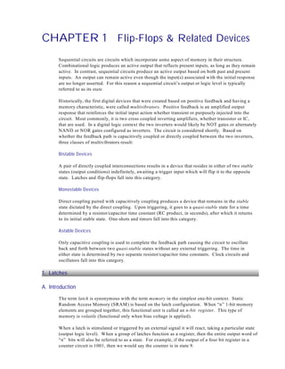
E. Setup and Hold Times
Edge triggered flip-flops perform according to specification only when the desired input, i.e. D in
Figure 1-23, is unchanging during an active clock edge. Otherwise, an undesirable phenomenon
know as metastability may occur. Setup time (tsu ) is the time the input must be unchanging,
preceding the clock edge. Hold time (th ) is the time the input must remain unchanging following
the clock edge. To illustrate, the manufacturer specified tsu and th have been represented by
crosshatch located at three active clock edges. Clock Î: a low which is to be written, is asserted
ahead of the clock edge but not maintained long enough to satisfy the hold time. Q therefore
cannot be guaranteed to be a correct low value after the clock. Clock Ï: there is no problem with
“hold time” but the low was not present long enough preceding the clock edge to satisfy “setup
time”. Clock Ð: a desirable situation where both “setup” and “hold” times are easily satisfied.
In Quartus II the term “slack” is used: (c) has the desired “setup” slack and “hold” slack (both
+ve), (b) has -ve “setup” slack while (a) has negative “hold” slack, which is unacceptable.
Figure 1-23 D Flip-Flop Setup and Hold Specifications.
Flip-flop input levels must be unchanging during an active clock edge (and have +ve slack), otherwise
the latched value will be unpredictable. Manufacturers guarantee performance based on minimum
requirements for setup (tsu) and hold (th ) times. (a) Setup is satisfied but the low is not held long
enough to satisfy the th requirement. (b) The low was not asserted soon enough to satisfy tsu (c)
The setup and hold requirements are easily met for the high to be reliably latched.
Modern flip-flops have tSU in the low 10’s of nanoseconds and t h as low as zero or slightly
negative. For these flip-flops, the t h requirement is always less than tp (typically 15 ns to 40 ns)
from clock to output Q, which ensures the correct operation of shift register type circuits.
Figure 1-24 Flip-Flop Timing Considerations.
For synchronous multi-flip-flop circuits to operate properly it is necessary for the hold time requirement
to be less than the propagation delay. (a) A 2-bit shift register (b) Q 0 output must be unchanging
during the active clock edge because it is the D 1 input. As illustrated, the hold time requirement is
easily satisfied because of propagation delay, and the 0 is correctly latched to Q 0.
3. Flip-Flops and Related Devices Pg. 21
Table 1-4 74VHC123 Truth Table.
Inputs Outputs
Function
&
A B &&&
C LR Q &
Q
H H pulse out
t W = Cx Rx
X L H L H inhibit
H X H L H inhibit
L H pulse out
L H pulse out
X X L L H reset
Figure 1-28 74VHC123 One-Shot .
The 74VHC123 retriggerable one-shot is a versatile modern version of an old device, having improved
characteristics. The calculation, tw = Cx Rx, is simplified and a broad range of values of R and C are
allowed. Schmitt trigger inputs are provided for both active high and low triggering. A low assertion of
CLR can be used to inhibit the output and when removed it also triggers the one-shot.
Clock Circuit
A versatile clock circuit based on a single 74VHC123 is shown in Figure 1-29. It has low and
high times which are set by separate Rx/Cx pairs. The first one-shot triggers the second after its
pulse time. The second then triggers the first in the same way, resulting in continuous
oscillations. For very large C values the device could be damaged when power is removed unless
a clamping diode is placed across Rx (see manufacturer’s data sheet).
Figure 1-29 74VHC123 Oscillator.
The two one-shots in a package allows a very simple but versatile clock circuit to be implemented.
There is full control over the pulse width and duty cycle by way of the variable resistors. An unused
input could be configured to inhibit the clock, if desired. f = 1/(t w1 +t w2), t w = Cx Rx. Pin numbers have
been included.
5. Flip-Flops in Quartus II.
The maxplus2 Quartus II Library contains the 74xx series flip-flops which can be used as needed.
However there are also some HDL based flip-flop megafunctions which allow multiple instances
and a degree of customization, such as the exclusion or inclusion of synchronous or asynchronous
set/reset inputs. The flip-flops are naturally positive edge triggered but the clock port can be
inverted to produce negative edge triggering. We will look briefly at a representative example.
4. Flip-Flops and Related Devices Pg. 27
Practice Problem Set 1-1 Chapter 1
1. Circle the correct true/false answer.
T F A 74HC00 can be configured as a debounce circuit for a single-pole double-throw switch
with the addition of external pull-up resistors.
T F A monostable device has two quasi-stable states.
T F A clock is an example of an astable multivibrator.
T F The basic latch is based on positive feedback around two inverters.
T F The SRAM cell that is typically used in FPGAs is essentially just a latch.
T F If a simple SR latch has both its S and R inputs asserted, it will operate in hold mode.
T F The SR latch which is based on two 2-input NOR gates will have active low S, R inputs.
T F The gated SR latch uses flow control gates to implement the Enable input.
T F Switch bounce is an oscillation caused by positive feedback.
T F The term “transparent” is descriptive of D latch operation when the latch is simply enabled.
T F The term flip-flop is used to describe latch type circuits that are edge triggered.
T F Edge detection circuitry in the 74HCxx series of flip-flops is based on the principle of a race
hazzard creating a very brief pulse.
T F A 74HC74 is a negative edge triggered D flip-flop.
T F Toggle flip-flop operation produces a divide by two action with respect to the clock.
T F The defining equation for the JK flip-flop is & Q + K & .
J Q
T F Set-up time is the time it takes for the Q output to display a response to the active clock edge.
T F The Hold time requirements of modern flip-flops is extremely small.
T F Other flip-flop types can be derived from the D flip-flop.
T F The data inputs of a LUT in a modern FPGA are hard wired in order to establish the desired
logic function.
T F It is important that a flip-flop exhibit set-up times that exceed its hold time requirements.
2. Complete the sketch of Q for the following SR latch.
5. Flip-Flops and Related Devices Pg. 31
Practice Problem Set 1-1 Chapter 1 SOLUTION
1. Circle the correct true/false answer.
T A 74HC00 can be configured as a debounce circuit for a single-pole double-throw switch
with the addition of external pull-up resistors.
F A monostable device has two quasi-stable states.
T A clock is an example of an astable multivibrator.
T The basic latch is based on positive feedback around two inverters.
T The SRAM cell that is typically used in FPGAs is essentially just a latch.
F If a simple SR latch has both its S and R inputs asserted, it will operate in hold mode.
F The SR latch which is based on two 2-input NOR gates will have active low S, R inputs.
T The gated SR latch uses flow control gates to implement the Enable input.
F Switch bounce is an oscillation caused by positive feedback.
T The term “transparent” is descriptive of D latch operation when the latch is simply enabled.
T The term flip-flop is used to describe latch type circuits that are edge triggered.
T Edge detection circuitry in the 74HCxx series of flip-flops is based on the principle of a race
hazzard creating a very brief pulse.
F A 74HC74 is a negative edge triggered D flip-flop.
T Toggle flip-flop operation produces a divide by two action with respect to the clock.
F The defining equation for the JK flip-flop is & Q + K & .
J Q
F Setup time is the time it takes for the Q output to display a response to the active clock edge.
T The hold time requirements of modern flip-flops is extremely small.
T Other flip-flop types can be derived from the D flip-flop by adding gating.
F The data inputs of a LUT in a modern FPGA are hard wired in order to establish the desired
logic function.
F It is important that a flip-flop exhibit setup times that exceed its hold time requirements.
2. Complete the sketch of Q for the following SR latch.