Arup Presentation Iqpc Warschau 03112010
•Download as PPTX, PDF•
1 like•887 views

Presentation given during the IQPC Bridge Symposium in Warsaw at the 4th of November 2010 about the Managing Contractor project Steel Bridge Renovation in the Netherlands

Recommended
Recommended
More Related Content
What's hot
What's hot (20)
Similar to Arup Presentation Iqpc Warschau 03112010
Similar to Arup Presentation Iqpc Warschau 03112010 (20)
Recently uploaded
Recently uploaded (20)
Arup Presentation Iqpc Warschau 03112010
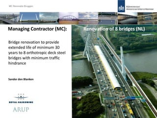
- 1. Sander den Blanken Managing Contractor (MC): Renovation of 8 bridges (NL) Bridge renovation to provide extended life of minimum 30 years to 8 orthotropic deck steel bridges with minimum traffic hindrance 1
- 2. Content: 1. The project (history & start) 2. The contract: Cost Plus Incentive Fee Contract 3. MC approach: BrIM & Technical 4. Current situation 5. Future developments 2Content
- 4. Experience RWS: • Until 2000 own engineering department • 2 Pilot projects: Moerdijk & Hagestein • Preferred solution: HSC overlay • Phd Study: HSC solution • Lessons Learned document • Several laboratorium tests • Reference Plan MC 41. The project
- 5. The Project: • Incentives contract for engineering firms: Managing Contractor • EPIC - Engineering, Procurement, Construction (traditional) • Asset Management: 8 major steel highways bridges 1960-1990 • Whole life cost assessment • Extending the life of existing assets > 30 Years • Orthotropic steel decks: Fatigue cracks & static strength issues • Local & global strengthening • Renovation in 6 years (2009-2015) • Incentive contract for 3 combinations for construction 51. The project
- 6. Main requirements: • Further 30 years life without significantly increased maintenance • Renovation with minimum/no traffic disruption • Implement high strength concrete overlay to improve deck fatigue performance 61. The project
- 7. Responsibility of Managing Contractor: • Delegated Client position • Project & contract management • Traffic & Environmental management • Project administration/project control • Technical Management: • Inspection 8 structures • Assessment 8 bridges, existing & strengthened condition • Design and engineer enhancement measures • Preparing tender documents • Management and supervision of the contractors 71. The project
- 8. Content: 1. The project (history & start) 2. The contract: Cost Plus Incentive Fee Contract 3. MC approach: BrIM & Technical 4. Current situation 5. Future developments 8Content
- 9. Contract: Costs Plus Incentive Fee (1) • Framework contract MC - RWS: 17 part orders (2 per bridge + 1) • Payments: • Costs: 2.8 x Gross Year Salary/2080 < SAL +OHC • Hours: approx 25.000 per bridge • Plus: Fixed Fee after finishing each part orders • Incentive Fee: Bonuses • Framework contract RWS/MC – Contractors (3): • Mini-tender per bridge • Same incentives as MC, and therefore same as RWS 92. The contract
- 10. Reference plan vs. Incentives MC • Reference plan made by Client based on own experience • Bonuses: 1. Minimise Traffic Hindrance: availability of lanes 2. Minimise Building Costs 3. Safety: no safety incidents + no shortcomings 4. Customer Evaluation: increase public opinion 5. Mobility 102. The contract
- 11. Content: 1. The project (history & start) 2. The contract: Cost Plus Incentive Fee Contract 3. MC approach: BrIM & Technical 4. Current situation 5. Future situation 11Content
- 12. General approach: MC Renovatie Bruggen – BrIM strategie • JV Royal Haskoning & Arup, Greisch • Get the best of each JV partner and cooperate • Working in the same office as Client with complete team • BrIM solutions to facilitate teams • Development MC along the project duration • Product & process development with contractors 123. MC approach: General
- 13. BrIM: Bringing pieces together MC Renovatie Bruggen – BrIM strategie •3D modelling of complex geometry • Creating of 2D drawings • Structural analysis • Document control • Availability of information 133. MC approach: BrIM
- 14. Project Wise • Working at same documents remotely • Document control • Storage of documents • QA system: • Control is automated • Notifications send for checking and approval • Documents only issued when trial is followed MC Renovatie Bruggen – BrIM strategie143. MC approach: BrIM
- 15. MC Renovatie Bruggen – BrIM strategie http://mcportal.arup.com/ 153. MC approach: BrIM
- 16. MC Renovatie Bruggen – BrIM strategie163. MC approach: BrIM
- 17. Content: 1. The project (history & start) 2. The contract: Cost Plus Incentive Fee Contract 3. MC approach: BrIM & Technical 4. Current situation 5. Future developments 17Content
- 18. Phased technical approach: 1. Initial global assessment: are the bridges adequate for strength with current lane layout 2. Detailed global strength and fatigue assessment & Detailed local fatigue assessment 3. Concept, scheme and detailed design of global and local strengthening 183. MC approach: Technical
- 19. Local fatigue assessment (1) • NEN-EN 1993-1-9:2006 - Eurocode 3: Design of steel structures – Part 1-9 • Load Model 5: • Weight in motion study (completed on Moerdijk bridge) • Trend factor to give vehicle numbers and axle loads • Current use and current layout • Convoy loading included • Influence of two lorries side-by-side included 193. MC approach: Technical
- 20. Local fatigue assessment (2) Important parameters influence on the estimation of fatigue damage: • Lane positions of lanes in relation to the main supporting structure • The lateral deviation of the trucks from lane centre (weave) • Influence of asphalt stiffness variation with temperature • Historical positions of the lanes • The distribution of traffic between on/off, slow and 1st fast lanes • Cracked / uncracked concrete 203. MC approach: Technical
- 21. Classification fatigue details: Detail category information taken from: •Kolstein’s Fatigue Classification of Welded Joints in Orthotropic Steel Bridge Decks •Eurocode 3, Part 1-9 213. MC approach: Technical
- 22. Local FEM for fatigue analysis of deck structure 223. MC approach: Technical
- 23. Validation • Compare with previous FE models (left) • Compare with strains measured on bridges (right) • Mean SN curves and mean stresses with actual damage 233. MC approach: Technical
- 24. Truck position • Position of vehicle compared to main structure • Variation of lateral position (Weave) 243. MC approach: Technical
- 25. Damage calculation VBA programme combines inputs from: - FE analysis - Loading regime (historic & future) - Weld characteristics - EC3 fatigue damage assessment 253. MC approach: Technical
- 26. Deck fatigue results Trough to deck plate joint: crack in weld Trough splice joints Trough to crossbea m joints (on trough) Trough to crossbeam joints (on web) Trough, deck plate and crossbeam joint Crossbe am to deck plate Deck plate butt welds Detail Category 50 36 124 71 125 100 36 Fatigue Detail 2 3 4 4a 5 6 7 Predicted Damage in 2010 PD-2010 10.90 26.55 0.13 0.01 1.23 0.00 0.04 Predicted damage 2040 Cracked- HSB, no steelwork repairs 2010 PD-2040-C 10.90 26.55 0.13 0.01 1.23 0.00 0.04 Predicted damage 2040 Cracked-HSB, submerged Arc steelwork repairs 2010 PD-2040-SA-C - - - - 0.36 - - Predicted damage 2040 Cracked- HSB, zero damage set at 2010 PD-2040-Z-C 0.90 9.39 0.00 0.00 0.16 0.00 0.00 Predicted damage – 2040 Cracked- HSB, Repair threshold limit of 0.66 damage set at 2010 - - - - 0.82 - - 263. MC approach: Technical
- 27. Deck fatigue solutions 273. MC approach: Technical
- 28. HSB Overlay •C90/105 Concrete •Closely spaced reinforcement •Minimal cover •tight tolerances HSB 284. Current situation: Muider
- 29. Edge Details HSB • Formed from angle sections and plates. • Designed for prefabrication. • Welded or epoxy fixed to deck plate. •Slotted holes for flexibility. • Starterbars welded to strip. Welded to deckplate Strip Starter barsAngle Weld Bolted connection 294. Current situation: Muider
- 30. Content: 1. The project (history & start) 2. The contract: Cost Plus Incentive Fee Contract 3. MC approach: BrIM & Technical 4. Current situation 5. Future developments 30Content
- 31. What’s happening now: • 2 bridges on-site • 1 bridge being tendered • 1 bridge at phase 3 assessment • 2 bridges beginning phase 2 314. Current situation
- 32. 1) Muider Bridge (special) • Under construction • Built in 1969 • Total length of 305m length, three spans • Two identical but structurally independent bridges each with a 18 m with. • Main load-bearing structure consists of 3 box-type main girders • Work currently in progress for local and global reinforcements supporting the bridge centrally with a free-standing suspended structure • Construction ends 1 Dec 2010 Project: Managing Contractor Project 324. Current situation: Muiderbrug
- 56. 2) Arch Beek Bridge • Built in 1967 • Spans a 4 tracks railway and a local road • 117 m long and 35 m of width • Steel tied arched bridge with free-standing arches • Construction starts September 2010 • Construction starteded on site 564. Current situation: Beek
- 57. Global Strengthening Measures – Beneath Structure • New plates • Several stiffeners • Additional flanges cross girders • Corner plates • Full penetration weld 574. Current situation: Beek
- 58. Global Strengthening Measures – Beneath Structure • Interaction with railways = 26 repairs 2 repairs 584. Current situation: Beek
- 59. 594. Current situation: Beek
- 60. 604. Current situation: Beek
- 61. Global Strengthening Measures – Above Deck • Strengthening Rivetted Connections Arch • Strengthening above arch • Overplate deck next to arch ends 614. Current situation: Beek
- 62. HSB Overlay 624. Current situation: Beek
- 63. Edge Details HSB 634. Current situation: Beek
- 64. 3) Scharberg Bridge • Being tendered • Built in 1972 • Spans both the Maas river and the Juliana Canal. • Total length of steel part is 301 m over 4 spans • Twin beam and slab bridge • Construction starts April 2011 644. Current situation: Scharberg
- 65. Deck Plate Repair & HSB Overlay 654. Current situation: Scharberg
- 66. Global Strengthening Measures • Either End Bearing Stiffeners - Additional stiffeners added • Full Height Stiffeners • Panel 1 Stiffeners • Type 6 Splice Plates • Bottom flange 664. Current situation: Scharberg
- 67. • Widening needed due to future traffic increase: option study • Construction starts June 2012 • Phase 3 just started 4) Galecopper Bridge • Built in 1975 • Canal span consists of two separate grid suspension bridges • Total length both bridges 320 m, width 34.6 m. • Pylons and suspension surface 674. Current situation: Galecopper
- 68. 5) Suurhoff Bridge • Built in 1972 • 2x2 traffic lanes and one parallel road opened for cyclists, pedestrians and agricultural traffic. • 3 main parts: – 40 m solid abutment – Bascule bridge with a facing tail – Main 2 spans of 95 and 55.7 meters • Construction starts on May 2012 • Phase 2 just started 68 4. Current situation: Suurhof
- 69. • Opened for traffic in 1976, after a construction time of almost 4 years. • A50 between Ewijk and Valburg junctions at Nijmegen • Spans the Waal and the flood plains of the Waal. • 2x2 traffic lanes, a hard shoulder and 2 parallel roads on both sides • Construction starts January 2014, phase 2 just started 6) 1st bridge at Ewijk 69 4. Current situation: Ewijk
- 70. Content: 1. The project (history & start) 2. The contract: Cost Plus Incentive Fee Contract 3. MC approach: BrIM & Technical 4. Current situation 5. Future developments 70Content
- 71. 7) Kreekrak Bridge • Opened for traffic in 1974 after a construction time of 4 years. • River span consists of two separate bridges with identical steel structure constructed from steel plate girders. • Total length is 240 m with four support points: two pillars and two abutments. • Partial overstresses are 50, 140 and 50 meters. • Each bridge with vehicle deck space for 2x2 traffic lanes and a hard shoulder. Project: Managing Contractor Project 715. Future: Kreekrak
- 72. • 2nd arch built in 1990 in order to double the lanes into twelve • Spanning the river Maas as two fixed bridges with a steel main span and a moveable part = already replaced • Western arch bridge 300 m span • The arch is connected by diagonal steel tension cables to steel main girders 3.90 m in height that carry the road deck. • Construction starts in April 2015 8) 2nd Van Brienenoord Bridge 725. Future: van Brienenoord
- 73. Other developments: 1. Local strengthening with glued steel plates (8-20 mm) on slow lane 2. HSB without reinforcement 3. Standardisation: repair methods, edge details, hsb overlay 4. Product development with contractors 5. Local strengthening with FRP (less stiffness, high strength) 6. Global replacement by combination of steel and FRP 735. Future developments
- 74. Questions? Next IQPC Bridge Symposium Frankfurt 27th of January 2010: • More results HSB & sensitivity analysis • Tests results HSB • New alternative: glued plate E: sander.den-blanken@arup.com 745. Future developments
Editor's Notes
- Reasons: high risks, lots of uncertainties on scope/limited starting information, flexibility till start of construction, increase speed of assessment, design & construction, multidisc approach: minimise traffic hindrance is key
- Develop approach & get to know each other, learn, share and listen Working remotely > 9 months (fortnightly meetings of 3 days)
- BrIM probeert verschillende puzzelstukjes te linken. Bespreek de voorbeelden die hier genoemd zijn. Omdat de puzzelstukjes verschillend zijn voor ieder project, moet BrIM aangepast worden op de specifieke eigenschappen van een project.
- ProjectWise is het basissysteem binnen BrIM. Dit stelt ons in staat om samen te werken aan documenten, het beheert te documenten, versienummering, et cetera.
- Geef eerst een demonstratie van de portal
- Geef eerst een demonstratie van de portal
- Position of lanes in relation to the main supporting structure The lateral deviation of the trucks from lane centre (weave) Influence of asphalt stiffness variation with temperature Historical positions of the lanes The distribution of traffic between on/off, slow and 1st fast lanes
- The edge details in the HSB are formed from steel angle sections or plates. They are designed to be prefabricated and to allow flexibility in height. Permanent edge of HSB detail (detail A): Comprises an angle section on outside face and a strip plate on inside face. The angle section is welded to the deckplates. They are connected together by bolts, both have slotted holes to allow variation in height. Starter reinforcement bars are welded to the plate. The main mat of reinforcement can then be lapped onto these starter bars. Edge detail between phases is similar in that the plates are bolted together and slotted holes allow variation in height. They are not full height of the HSB, to allow for concrete cover. The starter bars here sit at the top level of the vertical steel plate. The plates are attached to the deck with epoxy.
- First an overview of strengthening beneath the bridge. The area owned by Prorail covers half of the area beneath the bridge. New plates welded to botttom flange of girders in the corners of the bridge. Several stiffener details above bearings, including in the arch box (which requires access to the box). 3) 21 m long plates welded from below to underside of main cross girders. 3 of 5 are above the railway. 4) New full penetration butt weld details at 14 locations beneath the deck, 7 above railway. And weld repairs to trough-hoofddwarsdrager connections – large number.
- The troughs on the orthotropic deck are welded to the webs of main cross girders. There is a fatigue issue with this detail which means it must be replaced to give a 30 year residual life. As shown on diagram there are a large number of these locations on the bridge. Slightly less than half over the railway. The existing full penetration butt weld should be replaced with similar. This detail can be undertaken after installation of HSB, but in this case the method must be chosen not to excessively heat the deckplate and bonding layer above.
- This photograph illustrates the previously described measures. Note presence of bovenleiding close to underside of structure. Strengthening works must work around this.
- Now onto main structure strengthening measures above the deck. These measures must all be undertaken before installation of the the HSB. Rivetted connections in the arch require to be strengthened at each location where there is a change in angle. 2 extra stiffener plates required at ends of the arch, acute corners. 4 extra plates added to the deck plates near arch ends.
- Now onto main structure strengthening measures above the deck. These measures must all be undertaken before installation of the the HSB. Rivetted connections in the arch require to be strengthened at each location where there is a change in angle. 2 extra stiffener plates required at ends of the arch, acute corners. 4 extra plates added to the deck plates near arch ends.
- The edge details in the HSB are formed from steel angle sections or plates. They are designed to be prefabricated and to allow flexibility in height. Permanent edge of HSB detail (detail A): Comprises an angle section on outside face and a strip plate on inside face. The angle section is welded to the deckplates. They are connected together by bolts, both have slotted holes to allow variation in height. Starter reinforcement bars are welded to the plate. The main mat of reinforcement can then be lapped onto these starter bars. Edge detail between phases is similar in that the plates are bolted together and slotted holes allow variation in height. They are not full height of the HSB, to allow for concrete cover. The starter bars here sit at the top level of the vertical steel plate. The plates are attached to the deck with epoxy.
- Deck Repairs Beneath existing and historic lanes positions TOFD testing after asphalt removal Procedures for deck plate repair set out in specifications Cracks below deck The HSB Overlay represents the largest part of the works. Over full width of deck Installed in 2 traffic phases per bridge TOFD testing and deck plate repair required prior to installation Thickness varies Main features described above The HSB is the same width throughout and parallel to edges of bridge. The thickness varies due to the existing unevenness of the bridge deck (refer to alignment drawing)
- Full Heigth Stiffeners Required for Panels 1 to 4 Small Stiffeners Weld Strengthening Possibly