Gas Turbine Efficiency with Exhaust Heat Exchanger
1. THE EFFECT OF FRICTION ON THE JOULE CYCLE
TURBINE
The isentropic efficiency for a gas turbine is given by:
i = (Actual change in enthalpy)/(Ideal change in enthalpy)
i = (Actual change in temperature)/(Ideal change in temperature)
COMPRESSOR
For a compressor the isentropic efficiency is inverted and becomes as follows.
i = (Ideal change in enthalpy)/(Actual change in enthalpy)
hi = (Ideal change in temperature)/(Actual change in temperature)
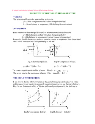
Remember that friction always produces a smaller change in temperature than for the ideal
case. This is shown on the T-s diagrams (fig.4a and 4b).
Fig.4a Turbine expansion. Fig.4b Compression process.
i = ((T3 – T4)/(T3 – T4’) i = (T2’ – T1)/(T2 – T1)
The power output from the turbine is hence P(out) = m c p (T3 – T4’) i
The power input to the compressor is hence P(in) = m cp (T2’ – T1)/ i
THE CYCLE WITH FRICTION
It can be seen that the effect of friction on the gas turbine cycle is reduced power output
and increased power input with an overall reduction in nett power and thermal efficiency.
Figs. 5a and 5b show the effect of friction on T-s and p-h diagrams for the Joule cycle.
Fig.5a Temperature - Entropy Fig.5b. Pressure - Enthalpy
Dr Subrata Das,Hindustan College of Science & Technology, Mathura.
2. A Joule Cycle uses a pressure ratio of 8. Calculate the air standard efficiency. The
isentropic efficiency of the turbine and compressor are both 90%. The low pressure in
the cycle is 120 kPa. The coldest and hottest temperatures in the cycle are 20oC and
1200oC respectively. Calculate the cycle efficiency with friction and deduce the
change. Calculate the nett power output. = 1.4 and cp = 1.005 kJ/kg K. Take the mass
flow as 3 kg/s.
No friction th = 1 - rp1/ -1 = 0.448 or 48.8 %
Withfriction T2' = 293 x 8 0.286 = 531 K
i = 0.9 = (531-293)/(T2-293) T 2 = 531 K
T4' = 1473/8 0.286 = 812.7 K
i = 0.9 = (1473-T4)/(1473-812.7) T 4= 878.7
th = 1 -(out)/ (in) = 1 - (T4-T1)/(T3-T2)
th= 0.36 or 36%
The change in efficiency is a reduction of 8.8%
(in) = m cp (T3-T2) = 3x1.005 x (1473-557) = 2760 kW
Nett Power Output = P(nett) = th x (in) = 0.36 x 2760 = 994 kW
A gas turbine uses a standard Joule cycle but there is friction in the compressor and
turbine. The air is drawn into the compressor at 1 bar 15 oC and is compressed with an
isentropic efficiency of 94% to a pressure of 9 bar. After heating, the gas temperature
is 1000oC. The isentropic efficiency of the turbine is also 94%. The mass flow rate is
2.1 kg/s. Determine the following.
1. The net power output.
2. The thermal efficiency of the plant.
= 1.4 and cp = 1.005 kJ/kg K.
(Answers 612 kW and 40.4%)
Dr Subrata Das,Hindustan College of Science & Technology, Mathura.
3. VARIANTS OF THE BASIC CYCLE
In this section we will examine how practical gas turbine engine sets vary from the basic
Joule cycle.
GAS CONSTANTS
The first point is that in reality, although air is used in the compressor, the gas going
through the turbine contains products of combustion so the adiabatic index and specific
heat capacity is different in the turbine and compressor.
FREE TURBINES
Most designs used for gas turbine sets use two turbines, one to drive the compressor and a
free turbine. The free turbine drives the load and it is not connected directly to the
compressor. It may also run at a different speed to the compressor.
Fig.shows such a layout with turbines in parallel configuration. Fig.b shows the layout
with series configuration.
Parallel turbines
b. Series turbines
Dr Subrata Das,Hindustan College of Science & Technology, Mathura.
8. EXHAUST HEAT EXCHANGERS
Because the gas leaving the turbine is hotter than the gas leaving the compressor, it is
possible to heat up the air before it enters the combustion chamber by use of an exhaust gas
heat exchanger. This results in less fuel being burned in order to produce the same
temperature prior to the turbine and so makes the cycle more efficient. The layout of such a
plant is shown on fig.
In order to solve problems associated with this cycle, it is necessary to determine the
temperature prior to the combustion chamber (T3).
A perfect heat exchanger would heat up the air so that T 3 is the same as T 5. It would also
cool down the exhaust gas so that T 6 becomes T 2. In reality this is not possible so the
concept of THERMAL RATIO is used. This is defined as the ratio of the enthalpy given to
the air to the maximum possible enthalpy lost by the exhaust gas. The enthalpy lost by the
exhaust gas is
H = mgcpg(T5-T6)
This would be a maximum if the gas is cooled down such that T 6 = T2. Of course in reality
this does not occur and the maximum is not achieved and the gas turbine does not perform
as well as predicted by this idealisation.
H(maximum) = H = mgcpg(T5-T6)
The enthalpy gained by the air is
H(air) = macpa(T3-T2)
Hence the thermal ratio is
T.R. = macpa(T3-T2)/ mgcpg(T5-T2)
The suffix ‘a’ refers to the air and g to the exhaust gas. Since the mass of fuel added in the
combustion chamber is small compared to the air flow we often neglect the difference in
mass and the equation becomes
25
23
..
TTc
TTc
RT
pg
pa
Dr Subrata Das,Hindustan College of Science & Technology, Mathura.
9. A gas turbine uses a pressure ratio of 7.5/1. The inlet temperature and pressure are
respectively 10 oC and 105 kPa. The temperature after heating in the combustion
chamber is 1300 oC. The specific heat capacity c p for air is 1.005 kJ/kg K and for the
exhaust gas is 1.15 kJ/kg K. The adiabatic index is 1.4 for air and 1.33 for the gas.
Assume isentropic compression and expansion. The mass flow rate is 1kg/s.
Calculate the air standard efficiency if no heat exchanger is used and compare it to the
thermal efficiency when an exhaust heat exchanger with a thermal ratio of 0.88 is used.
Referring to the numbers used on fig.8 the solution is as follows.
Air standard efficiency = 1 - rp
(1-1/ )
= 1-7.5
0.286
= 0.438 0r 43.8%
Solution with heat exchanger
T2 =T1rp
(1-1/ )
= 283 (7.5)
0.286
=503.6 K
T5=T4/rp
(1-1/ )
= 1573/(7.5)
0.25
= 950.5 K
Use the thermal ratio to find T3.
K953.6
6.5035.95015.1
6.503T1.005
15.1
T1.005
88.0
3
3
25
23
T
TT
T
In order find the thermal efficiency, it is best to solve the energy transfers.
P(in)= mcpa(T2-T1) = 1 x 1.005 (503.6-283) = 221.7 kW
P(out) = mcpg(T4-T5) = 1 x 1.15 (1573-953.6) = 712.3 kW
P(nett) = P(out) - P(in) = 397.3 kW
(in)combustion chamber) = mcpg(T4-T3)
(in)= 1.15(1573-953.6) = 712.3 kW
th = P(nett)/ (in) = 494.2/712.3 = 0.693 or 69.3%
Dr Subrata Das,Hindustan College of Science & Technology, Mathura.
10. 1. A gas turbine uses a pressure ratio of 7/1. The inlet temperature and pressure are
respectively 10 oC and 100 kPa. The temperature after heating in the combustion
chamber is 1000 oC. The specific heat capacity c p is 1.005 kJ/kg K and the adiabatic
index is 1.4 for air and gas. Assume isentropic compression and expansion. The mass
flow rate is 0.7 kg/s.
Calculate the net power output and the thermal efficiency when an exhaust heat
exchanger with a thermal ratio of 0.8 is used.
(Answers 234 kW and 57%)
2. A gas turbine uses a pressure ratio of 6.5/1. The inlet temperature and pressure are
respectively 15oC and 1 bar. The temperature after heating in the combustion chamber
is 1200 oC. The specific heat capacity c p for air is 1.005 kJ/kg K and for the exhaust
gas is 1.15 kJ/kg K. The adiabatic index is 1.4 for air and 1.333 for the gas. The
isentropic efficiency is 85% for both the compression and expansion process. The mass
flow rate is 1kg/s.
Calculate the thermal efficiency when an exhaust heat exchanger with a thermal ratio
of 0.75 is used.
(Answer 48.3%)
11. A gas turbine has a free turbine in parallel with the turbine which drives the
compressor. An exhaust heat exchanger is used with a thermal ratio of 0.8. The
isentropic efficiency of the compressor is 80% and for both turbines is 0.85.
The heat transfer rate to the combustion chamber is 1.48 MW. The gas leaves the
combustion chamber at 1100 oC. The air is drawn into the compressor at 1 bar and
25oC. The pressure after compression is 7.2 bar.
The adiabatic index is 1.4 for air and 1.333 for the gas produced by combustion. The
specific heat c p is 1.005 kJ/kg K for air and 1.15 kJ/kg K for the gas. Determine the
following.
i. The mass flow rate in each turbine.
ii. The net power output.
iii. The thermodynamic efficiency of the cycle.
T1 = 298 K
T2= 298(7.2)
(1-1/1.4)
= 524 K
T4 = 1373 K
T5 = 1373(1/7.2)
(1-1/1.333)
= 838.5 K
COMPRESSOR
i = 0.8 = (524-298)/(T2-298) hence T2= 580.5 K
TURBINES
Treat as one expansion with gas taking parallel paths.
i = 0.85 = (1373-T5)/(1373-838.5) hence T5 = 918.7 K
HEATEXCHANGER
Thermal ratio = 0.8 = 1.005(T
3
-580.5)/1.15(918.7-580.5)
henceT3= 890.1 K
COMBUSTION CHAMBER
(in)= mcp(T4-T3) = 1480 kW
1480 = m(1.15)(1373-890.1) hence m = 2.665 kg/s
COMPRESSOR
P(in) = mcp (T2-T1) = 2.665(1.005)(580.5-298) = 756.64 kW
Dr Subrata Das,Hindustan College of Science & Technology, Mathura.
12. TURBINE A
P(out) = 756.64 kW = mAcp(T4-T5)
756.64 = = 2.665(1.15)(1373-918.7) hence mA= 1.448 kg/s
Hence mass flow through the free turbine is 1.2168 kg/s
P(nett) = Power from free turbine =1.2168(1.15)(1373-918.7) = 635.7 kW
THERMODYNAMIC EFFICIENCY
th = P(nett)/ (in)= 635.7/1480 = 0.429 or 42.8 %
1. List the relative advantages of open and closed cycle gas turbine engines.
Sketch the simple gas turbine cycle on a T-s diagram. Explain how the efficiency can
be improved by the inclusion of a heat exchanger.
In an open cycle gas turbine plant, air is compressed from 1 bar and 15 oC to 4 bar. The
combustion gases enter the turbine at 800 oC and after expansion pass through a heat
exchanger in which the compressor delivery temperature is raised by 75% of the
maximum possible rise. The exhaust gases leave the exchanger at 1 bar. Neglecting
transmission losses in the combustion chamber and heat exchanger, and differences in
compressor and turbine mass flow rates, find the following.
(i) The specific work output.
(ii) The work ratio
(iii) The cycle efficiency
The compressor and turbine polytropic efficiencies are both 0.84.
Compressor c p = 1.005 kJ/kg K = 1.4
Turbine cp = 1.148 kJ/kg K = 1.333
Dr Subrata Das,Hindustan College of Science & Technology, Mathura.
13. 2. A gas turbine for aircraft propulsion is mounted on a test bed. Air at 1 bar and 293K
enters the compressor at low velocity and is compressed through a pressure ratio of 4
with an isentropic efficiency of 85%. The air then passes to a combustion chamber
where it is heated to 1175 K. The hot gas then expands through a turbine which drives
the compressor and has an isentropic efficiency of 87%. The gas is then further
expanded isentropically through a nozzle leaving at the speed of sound. The exit area
of the nozzle is 0.1 m2. Determine the following.
(i) The pressures at the turbine and nozzle outlets.
(ii) The mass flow rate.
(iii) The thrust on the engine mountings.
Assume the properties of air throughout.
Dr Subrata Das,Hindustan College of Science & Technology, Mathura.
A gas turbine plant operates with a pressure ratio of 6 and a turbine inlet
temperature of 927 oC. The compressor inlet temperature is 27
o
C. The isentropic
efficiency of the compressor is 84% and of the turbine 90%. Making sensible
assumptions, calculate the following.
(i) The thermal efficiency of the plant.
(ii) The work ratio.
Treat the gas as air throughout.
If a heat exchanger is incorporated in the plant, calculate the maximum possible
efficiency which could be achieved assuming no other conditions are changed.
Explain why the actual efficiency is less than that predicted.