PLC arithmatic functions
•
4 j'aime•5,400 vues

plc, PLC Applications, Programmable Logic Controllers, Programmable, Logic, Controllers, PROGRAMMING, gates, COUNTERS, Timers,LOGIC CIRCUITS, INTERNAL RELAYS, ARITHMETIC FUNCTIONS, Application, Data Types and Addressing,

Recommandé
Contenu connexe
Tendances
Tendances (20)
En vedette
En vedette (20)
Similaire à PLC arithmatic functions
Similaire à PLC arithmatic functions (20)
Plus de Ameen San
Plus de Ameen San (16)
Dernier
Dernier (20)
PLC arithmatic functions
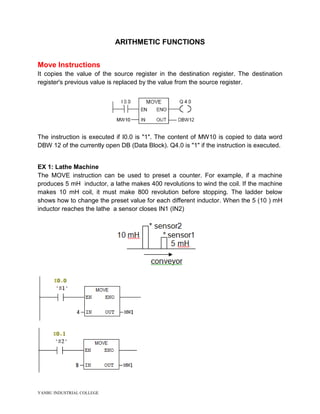
- 1. YANBU INDUSTRIAL COLLEGE ARITHMETIC FUNCTIONS Move Instructions It copies the value of the source register in the destination register. The destination register's previous value is replaced by the value from the source register. The instruction is executed if I0.0 is "1". The content of MW10 is copied to data word DBW 12 of the currently open DB (Data Block). Q4.0 is "1" if the instruction is executed. EX 1: Lathe Machine The MOVE instruction can be used to preset a counter. For example, if a machine produces 5 mH inductor, a lathe makes 400 revolutions to wind the coil. If the machine makes 10 mH coil, it must make 800 revolution before stopping. The ladder below shows how to change the preset value for each different inductor. When the 5 (10 ) mH inductor reaches the lathe a sensor closes IN1 (IN2)
- 2. YANBU INDUSTRIAL COLLEGE EX 2: Selecting motor duration The parts in a production line have two sizes, as in the above task. When a large piece comes under the drill machine, a large hole has to be drilled (corresponding to 10 s), For a small piece, 5 seconds is enough to drill a hole. Design and test a ladder diagram to achieve this.
- 3. YANBU INDUSTRIAL COLLEGE EX 3: Temperature monitor In an industrial process it is required to keep the temperature between 120 and 570 o C. If the temperature is within the range, a green lamp is on. Otherwise a red is on. For this try the following ladder Network 1: A Temperature sensor provides the actual temperature as 150 o C. Move it to the memory word address MW1 150 MW1 Figure 6. Network 2 Compare the value in MW1 with the allowed temperature range. M0.0 ( ) MW1 MW1 120 570 Figure 7. Network 3 Q125.0 = green lamp. Network 4 Q125.1 = red lamp. MOVE IN OUT CMP>1 IN1 IN2 OUT CMP<1 IN1 IN2 OUT
- 4. YANBU INDUSTRIAL COLLEGE Mathematical Instructions ADD_I Add Integer ADD_I (Add Integer) is activated by a logic "1" at the Enable (EN) Input. IN1 and IN2 are added and the result can be scanned at OUT. If the result is outside the permissible range for an integer (16-bit), the OV bit and OS bit will be "1" and ENO is logic "0", so that other functions after this math box which are connected by the ENO (cascade arrangement) are not executed. The ADD_I box is activated if I0.0 = "1". The result of the addition MW0 + MW2 is output to MW10. If the result was outside the permissible range for an integer, the output Q4.0 is set. EX 1: Counting circuit for two conveyors Figure below shows two conveyors used in a manufacturing process. Each photo detectors counts the work pieces as they pass by. Obtain the total count from the two conveyors Pulses Conveyor 1 Light source (IN1) Conveyor 2 (IN2) The ladder logic below achieves the control objectives required PLC
- 5. YANBU INDUSTRIAL COLLEGE SUB_I Subtract Integer SUB_I (Subtract Integer) is activated by a logic "1" at the Enable (EN) Input. IN2 is subtracted from IN1 and the result can be scanned at OUT. If the result is outside the permissible range for an integer (16-bit), the OV bit and OS bit will be "1" and ENO is logic "0", so that other functions after this math box which are connected by the ENO (cascade arrangement) are not executed.
- 6. YANBU INDUSTRIAL COLLEGE The SUB_I box is activated if I0.0 = "1". The result of the subtraction MW0 - MW2 is output to MW10. If the result was outside the permissible range for an integer or the signal state of I0.0 = 0, the output Q4.0 is set. Ex 2: Counting sound parts Figure below shows a main conveyor with a diverter gate for defective parts. Write a program using subtraction function that determine the number of parts that passed inspection Reject coveyor Reject counter Main - Conveyor Main counter Diverter Figure 14.
- 7. YANBU INDUSTRIAL COLLEGE MUL_I Multiply Integer MUL_I (Multiply Integer) is activated by a logic "1" at the Enable (EN) Input. IN1 and IN2 are multiplied and the result can be scanned at OUT. If the result is outside the permissible range for an integer (16-bit), the OV bit and OS bit will be "1" and ENO is logic "0", so that other functions after this math box which are connected by the ENO (cascade arrangement) are not executed. The MUL_I box is activated if I0.0 = "1". The result of the multiplication MW0 x MW2 is output to MW10. If the result was outside the permissible range for an integer, the output Q4.0 is set. Ex 3: Total plant bottle count Figure below shows a conveyor transporting cartons (counted with a counter). Each carton has 12 bottles. Develop a ladder diagram to find the total plant bottle production. Counter
- 8. YANBU INDUSTRIAL COLLEGE Ex 4: Power Generation Monitoring If the power generated does not exceed the max limit of 200/3 = 66.7 MW/phase, a green lamp is on, and otherwise a red lamp is on. Calculate the active power cos..IVP , the angle in radians, where ,36.63/11 KVV ,10KAI .1.0 rad Complete the ladder below. ________________________________ DIV_I Divide Integer DIV_I (Divide Integer) is activated by a logic "1" at the Enable (EN) Input. IN1 is divided by IN2 and the result can be scanned at OUT. If the result is outside the permissible range for an integer (16-bit), the OV bit and OS bit is "1" and ENO is logic "0", so that other functions after this math box which are connected by ENO (cascade arrangement) are not executed. The DIV_I box is activated if I0.0 = "1". The result of the division MW0 by MW2 is output to MW10. If the result was outside the permissible range for an integer, the output Q4.0 is set.
- 9. YANBU INDUSTRIAL COLLEGE Ex 5: Total plant carton count Similar to task 4 however the number of bottles is counted (using a counter).Develop a ladder diagram to count the number of cartons (each having 6 bottles).