VVIP Pune Call Girls Warje (7001035870) Pune Escorts Nearby with Complete Sat...
Service Presentation Advanced M52.pdf
1. Mission Critical Climate Control
Advanced M52 Controller
P R O D U C T
4
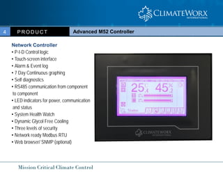
Network Controller
• P-I-D Control logic
• Touch-screen interface
• Alarm & Event log
• 7 Day Continuous graphing
• Self diagnostics
• RS485 communication from component
to component
• LED indicators for power, communication
and status
• System Health Watch
• Dynamic Glycol Free Cooling
• Three levels of security
• Network ready Modbus RTU
• Web browser/ SNMP (optional)
4. Mission Critical Climate Control
Advanced M52 Controller
P R O D U C T
4
Process Status Display
This region shows the current operating status of the
system by means of graphic icons and analogue bar
5. Mission Critical Climate Control
Advanced M52 Controller
P R O D U C T
4
On/ Off Mode Icon
The On/Off mode icons keep you aware of the current On/Off mode
selection. The On/Off mode selection can be set in the “On/Off
mode” setting under the {Setting} tab.
6. Mission Critical Climate Control
Advanced M52 Controller
P R O D U C T
4
Co-Work Mode Icon
This shows the Co-Work™ operation mode and Co-work network address.
Duty Master (e.g. Address 1) Duty Slave (e.g. Address 1)
Co-work icon visible only when the unit is connected in a Co-work network
7. Mission Critical Climate Control
Advanced M52 Controller
P R O D U C T
4
Co-Work Mode Icon
This shows the Co-Work™ operation mode and Co-work network address.
8. Mission Critical Climate Control
Advanced M52 Controller
P R O D U C T
4
Security
The factory default password and access right for each security level is summarized in the
following table:
Function / Description Level 1 Level 2 Level 3
Default password 1024 4321 1234
Local on/off control
Alarm clear
Alarm configuration
Time schedule / clock
Setting - configuration 1
Setting - configuration 2
Setting - reading
Setting - control parameter
Testmode - Microprocessor board
Testmode - digital I/O board
Testmode - sensor
Testmode - default value
9. Mission Critical Climate Control
Advanced M52 Controller
P R O D U C T
4
Security
To invoke security log-in or log-out, simply press the active tab on the
Tab bar:
Press active tab
not logged-in already logged-in
12. Mission Critical Climate Control
Advanced M52 Controller
P R O D U C T
4
Alarm configuration will be automatically synchronized across the Co-Work
network.
Every alarm has a number of configuration options. You can customize the way
alarms are reported and what automatic actions will be performed.
13. Mission Critical Climate Control
Advanced M52 Controller
P R O D U C T
4
Historical Event Log
Log date
Event description
Scroll bar Log time
Unit no.
14. Mission Critical Climate Control
Advanced M52 Controller
P R O D U C T
4
Historical Event Log
Alarm raised
Alarm acknowledged
Power failure / Power restore / Unit start / Unit stop
Alarm cleared
18. Mission Critical Climate Control
Advanced M52 Controller
P R O D U C T
4
Temperature and Humidity Log Graph
Switch curve display - to cycle temperature only,
humidity only or both curves display.
Zoom in & Zoom out - to enlarge or reduce the scale
of the curve display.
Guide movement - to move the guide along the time
axis.
21. Mission Critical Climate Control
Advanced M52 Controller
P R O D U C T
4
Settings Summary Glossary
Page 1 : Readings 1
Description Range Default Units Definition
Software version - - - Version of software operating on the microprocessor main board
Co-Work ID 1-16 - - Specific unit address in the Co-Work network
Co-Work Total 1-16 - - Total number of members in the Co-Work network
*CW EWT 1 0-45 - °C Chilled Water entering temperature circuit 1 (optional)
*CW LWT 1 0-45 - °C Chilled Water leaving temperature circuit 1 (optional)
*CWEWT 2 0-45 - °C Chilled Water entering temperature circuit 2 (optional)
*CW LWT 2 0-45 - °C Chilled Water leaving temperature circuit 2 (optional)
*Temp. Return Air 0-50 - °C Temperature of sensor designated as return air
*Temp. Supply Air 0-50 - °C Temperature of sensor designated as supply air
Hum. Return Air 0-99.9 - % RH Humidity of sensor designated at return air
Hum. Supply Air 0-99.9 - % RH Humidity of sensor designated at supply air
*TempFilterDrierA1 0-45 - °C Refrigerant temperature entering Filter Drier Circuit 1 (optional)
*Temp.FilterDrierB1 0-45 - °C Refrigerant temperature leaving Filter Drier Circuit 1 (optional)
*Temp.FilterDrierA2 0-45 - °C Refrigerant temperature entering Filter Drier Circuit 2 (optional)
*Temp.FilterDrierB1 0-45 - °C Refrigerant temperature leaving Filter Drier Circuit 2 (optional)
*Temp. Glycol 0-45 - °C Temperature of Glycol used in the Glycol Free Cooling Configuration
22. Mission Critical Climate Control
Advanced M52 Controller
P R O D U C T
4
Settings Summary Glossary
Page 1 : Readings 1
Description Range Default Units Definition
Air Pressure 0-9.9 - Ps Pressure reading from a transducer either under floor or in a duct (optional)
Suction Pressure1 0-300 - Ps Pressure reading from a pressure transducer Circuit 1(optional)
Discharge Pressure1 15-515 - Ps Pressure reading from a pressure transducer Circuit 1(optional)
Suction Pressure2 0-300 - Ps Pressure reading from a pressure transducer Circuit 2(optional)
Discharge Pressure2 15-515 - Ps Pressure reading from a pressure transducer Circuit 2(optional)
Voltage 50-130 - % Control voltage output
Fan runtime 0-65535 - hours Total fan run time
Comp 1 runtime 0-65535 - hours Total compressor run time Circuit 1
Comp 2 runtime 0-65535 - hours Total compressor run time Circuit 2
Heater 1 runtime 0-65535 - hours SCR Heater run time or heater 1 runtime if no SCR
Heater 2 runtime 0-65535 - hours Heater 2 run time
Heater 3 runtime 0-65535 - hours Heater 3 run time
Humid runtime 0-65535 - hours Total humidifier run time
Cooling runtime 1 0-65535 - hours Total cooling run time Circuit 1
Cooling runtime 2 0-65535 - hours Total cooling run time Circuit 2
23. Mission Critical Climate Control
Advanced M52 Controller
P R O D U C T
4
Settings Summary Glossary
Page 2 : Readings 2
Description Range Default Units Definition
EXT1 Software ver - - - Version of software operating on the microprocessor expansion board circuit 1
EXT2 Software ver - - - Version of software operating on the microprocessor expansion board circuit 2
*Suction Temp 1 0-30 - °C Suction Temperature reading from circuit 1 (optional)
*Suction Temp 2 0-30 - °C Suction Temperature reading from circuit 2 (optional)
*Suction Cal.Temp 1 -10-40 - °C Saturated Suction Temperature calculated from Suction pressure circuit 1 (optional used with E txv)
*Suction Cal.Temp 2 -10-40 - °C Saturated Suction Temperature calculated from Suction pressure circuit 2 (optional used with E txv)
E TX Valve 1 Step 2-16 - Step Operating increments for the Electronic Expansion valve circuit 1 (optional)
E TX Valve 2 Step 2-16 - Step Operating increments for the Electronic Expansion valve circuit 2 (optional)
Comp1 VFD Speed 1200-7200 - rpm Speed that the VFD is operating at circuit 1 (optional)
Comp2 VFD Speed 1200-7200 - rpm Speed that the VFD is operating at circuit 2 (optional)
Comp1 DC Voltage 400-600 - Volts Output voltage measurement circuit 1 (optional)
Comp2 DC Voltage 400-600 - Volts Output voltage measurement circuit 2 (optional)
Comp1 VFD Amps 1-50 - Amps Output amp measurement circuit 1 (optional)
Comp2 VFD Amps 1-50 - Amps Output amp measurement circuit 2 (optional)
*IPM 1 Temp. 30-80 - °C Internal temperature of VFD Intelligent power module circuit 1 (optional)
*IPM 2 Temp. 30-80 - °C Internal temperature of VFD Intelligent power module circuit 2 (optional)
VFD 1 State. 0-20 - 00 Status of VFD circuit 1 (optional)
VFD 2 State. 0-20 - 00 Status of VFD circuit 2 (optional)
24. Mission Critical Climate Control
Advanced M52 Controller
P R O D U C T
4
Settings Summary Glossary
Page 3 : Configuration 1
Description Range Default Units Synchronization Definition
No. of duty unit 1-16 1 - Units required to run together in a Co-Work network to satisfy the load.
*Temp. set point 12-30 22 °C Controls space temperature based on return or supply air temperature.
*Temp. set point 53-86 72 °F Controls space temperature based on return or supply air temperature.
Humid. Set point 30-80 50 % RH Controls space humidity based on return or supply air humidity
Ht/Dehum/Hum Fan 10-100 80 % Sets the fan speed when humidification/heating or dehum demand is present.
Standby Fan 0-100 0 % Sets the fan speed when the unit is in standby operation
Cooling Min Fan 10-100 65 % Sets the minimum fan speed when cooling demand is not present
Cooling Max Fan 10-100 90 % Sets the maximum fan speed when cooling demand is present
CW Valve Start - Pt 10-100 20 % Sets the minimum demand required for the CW valve to begin opening
Discharge Set - Pt 10-500 275 Ps Sets the fan speed based on static pressure
Discharge Dead Bd 1-50 10 Ps Tolerance for discharge fan speed pressure
Water Reg Min AO 10-100 20 % Minimum open setting for modulating water regulating valve
Comp. Max Speed 0-7200 5400 rpm Sets the maximum compressor speed when cooling demand is present.
Comp. Min Speed 0-7200 1200 rpm Sets the minimum compressor speed when cooling demand is not present.
Comp. Hum Speed 0-7200 2400 rpm Sets the compressor speed when humidity control is required.
25. Mission Critical Climate Control
Advanced M52 Controller
P R O D U C T
4
Settings Summary Glossary
Page 4 : Configuration 2
Description Range Default Units Synchronization Definition
Baud rate 1200-19.2k 2400 bps Network communication speed
On/Off mode Local/Remote/Timer Local - Sets unit to turn “ON” and “OFF” by local keypad, remote signal or timer schedule.
Auto changeover 0-9999 24 hours Time interval after which duty and standby unit switch in a Co-Work network
Warm-up period 0-180 120 seconds Allows sensor reading to stabilize before tripping alarms
Fan purge delay 0-9999 120 seconds Runs fan for minimum time to dissipate heat in components before fan shuts down
Comp. elapse 30-300 180 seconds Prevents compressors from restarting for minimum time after stopping
Comp. Min time 30-300 180 seconds Prevents compressors from running for less than this time
Pos. start delay 0-600 180 seconds By passes refrigerant low-pressure switch and alarm during compressor start-up to
prevent nuisance alarms in cold weather.
Humid. Fault delay 0-9999 900 seconds Connected to the humidifier high water level sensor and delays boiler dirty alarm to
prevent nuisance alarms on humidifier start-up.
Liquid H/L Fault delay 0-30 0 seconds Time interval to activate alarm after fault has been detected.
*Temp. units °C/°F °C - Sets ALL temperature display units to °F or °C
Sensor display Unit/ Site Unit - In a Co-Work network choose to display the individual unit sensor readings or the
average readings (SITE readings are the average of all sensor readings in a Co-Work
network)
Language English/ Chinese English - Choose between English and Chinese
Control Sensor Return/Supply/ Mix Return - Enables the unit to be controlled by Supply or Return Air Sensor. Mix is Supply
Temperature and Return Humidity.
26. Mission Critical Climate Control
Advanced M52 Controller
P R O D U C T
4
Settings Summary Glossary
Page 5 : Configuration 3
Description Range Default Units Synchronization Definition
*Temp. dead band 0-10 2 °C Tolerance for return air, + or – ½ deadband. Range of temperature where temperature control
operation does not change
*Relaxed band Temp 0-20 5 °C Used in the timer schedule allows an alternate deadband setting
*Temp. dead band 0-18 0 °F Tolerance for return air, + or – ½ deadband. Range of temperature where temperature control
operation does not change
*Relaxed band Temp 0-36 9 °F Used in the timer schedule allows an alternate deadband setting
Hum. Dead band 0-30 6 %RH Tolerance for return air, + or – ½ deadband. Range of humidity where humidity control
operation does not changes
Relaxed band Humid 0-50 20 %RH Used in the timer schedule allows an alternate deadband setting
*Prop. band Cool 1-10 2 °C Temperature range over which all cooling stages are equally activated or chilled water valve
modulates to full open.
*Prop. band Heat 1-10 2 °C Temperature range over which all heater are modulated (Staged AP)
*Prop. band Cool 2-18 4 °F Temperature range over which all cooling stages are equally activated or chilled water valve
modulates to full open.
*Prop. band Heat 2-18 4 °F Temperature range over which all heater are modulated (Staged AP)
Prop. band Humid 2-10 5 %RH Humidity range over which all humidifier stages are equally activated.
Prop. band Dehum 2-10 5 %RH Humidity range over which all dehumidification stages are equally activated or chilled water
valve modulates to full open.
27. Mission Critical Climate Control
Advanced M52 Controller
P R O D U C T
4
Settings Summary Glossary
Page 5 : Configuration 3
Description Range Default Units Synchronization Definition
Temp. I-time 1-30 30 seconds Integral action time constant used in the PID control loop
Humid. I-time 1-30 30 seconds Integral action time constant used in the PID control loop
Temp. D-time 0-61 15 - Derivative function used in PID control loop
Humid. D-time 0-94 15 - Derivative function used in PID control loop
Humid. Control Enable/ Disable Enable - Choose to enable or disable humidity control or control Humidification.
Reheat Control Enable/ Disable Enable - Choose to enable or disable reheat control or control reheat.
Dehum. Control Enable/ Disable Enable - Choose to enable or disable humidity control or control Dehumidification.
Free Cooling Control Enable/ Disable Enable - Choose to enable or disable Glycol Free Cooling
*Free Cooling T/D 3-7 3 °C Adjusts the temperature difference change over set point for Economizer to DX change over.
*Free Cooling H/L 4-12 7.2 °C Adjusts the change over set point for Economizer to DX change over.
*Free Cooling T/D 6-14 6 °F Adjusts the temperature difference change over set point for Economizer to DX change over.
*Free Cooling H/L 39-54 45 °F Adjusts the change over set point for Economizer to DX change over.
Damper end switch delay
Temp Control
30-180
AVG/ Max
30
AVG
Seconds
-
Adjusts the time for the fan to turn on in damper applications.
When multiple sensors are used allows control by Average or Maximum
28. Mission Critical Climate Control
Advanced M52 Controller
P R O D U C T
4
Settings Summary Glossary
Page 6 : Configuration 4
Description Range Default Units Definition
System Type CHW/Single/Dual Dual - Identifies cooling type and number of stages
Control Mode Auto/Manual Auto - This function is used in the test mode to be able to select manual operation and activate devises
manually from the test mode pages.
Restart delay 0-9999 10 seconds Delays the unit from starting until the time limit expires.
Network address 1-99 1 - Controller address to identify the unit in a BMS network.
Sensor Mode Local/Remote/Disable Local - Enables or disables the unit air temperature sensor from the averaging features in a Co-Work network
during standby periods. Also used for disabling sensor for demonstrations.
Heater Min. On 0-100 20 % Sets the minimum demand required for the Reheat to begin operating.
Cool Min. On 0-100 20 % Sets the minimum demand required for the Cooling to begin operating
*R. Temp Hi limit 12-37 30 °C Maximum of controlling return temperature sensor before activating alarm
*R. Temp Low limit 5-30 15 °C Minimum of controlling return temperature sensor before activating alarm
*R. Temp Hi limit 53-99 86 °F Maximum of controlling return temperature sensor before activating alarm
*R. Temp Low limit 41-86 59 °F Minimum of controlling return temperature sensor before activating alarm
Humid. Hi limit 50-90 70 % RH Maximum of controlling return humidity sensor before activating alarm
Humid Lo limit 20-50 30 % RH Minimum of controlling return humidity sensor before activating alarm
29. Mission Critical Climate Control
Advanced M52 Controller
P R O D U C T
4
Settings Summary Glossary
Page 6 : Configuration 4
Description Range Default Units Definition
*S. Temp Hi limit 12-37 30 °C Maximum of controlling supply temperature sensor before activating alarm
*S. Temp Low limit 5-30 15 °C Minimum of controlling supply temperature sensor before activating alarm
*S. Temp Hi limit 53-99 86 °F Maximum of controlling supply temperature sensor before activating alarm
*S. Temp Low limit 41-86 59 °F Minimum of controlling supply temperature sensor before activating alarm
Volt Hi limit 102-120 115 % Maximum allowable voltage before activating alarm
Volt Low limit 80-98 85 % Minimum allowable voltage before activating alarm
Volt adjust 80-120 100 % Calibration function used to fine tune the voltage reading from the control transformer.
*R. temp offset +5 /- 5 0 °C Calibration function used to fine tune the return temperature sensor reading.
*R. temp offset +10/ -10 0 °F Calibration function used to fine tune the return temperature sensor reading.
R. hum offset +10/ -10 0 % RH Calibration function used to fine-tune the return humidity sensor reading.
*S. temp offset +5 /- 5 0 °C Calibration function used to fine tune the supply temperature sensor reading.
*S. temp offset +10/ -10 0 °F Calibration function used to fine tune the supply temperature sensor reading.
S. hum offset +10/ -10 0 % RH Calibration function used to fine-tune the supply humidity sensor reading.
30. Mission Critical Climate Control
Advanced M52 Controller
P R O D U C T
4
Settings Summary Glossary
Page 7 : Configuration 5
Description Range Default Units Definition
*Max Superheat Temp 2-20 10 °C Sets the maximum superheat when a electronic txv valve is used
*Max Superheat Temp 36-68 50.0 °F Sets the maximum superheat when a electronic txv valve is used
*Min Superheat Temp 1-10 7 °C Sets the minimum superheat when a electronic txv valve is used
*Min Superheat Temp 34-50 44.6 °F Sets the minimum superheat when a electronic txv valve is used
E TX Max Step 0-750 450 - Sets the maximum step (open) when a electronic txv valve is used
E TX Min Step 0-750 100 - Sets the minimum step (closed)when a electronic txv valve is used
Valve Adjust Time 10-360 60 seconds Sets the interval time between adjustments of the electronic txv valve
Initial Valve Step 0-750 250 - Sets the initial increment that the electronic txv valve opens
Low Pressure Reset 20-100 6 psi Pressure point that is used to opens the E TX valve regardless of super heat
E TX Valve Step 2-20 4 - Number of steps valve is being opened based on above condition
Comp1 VFD Speed 1200-7200 0 rpm Speed that compressor 1 will operate at in manual mode
Comp 2 VFD Speed 1200-7200 0 rpm Speed that compressor 2 will operate at in manual mode
Fan Run Time Reset - - - Resets fan run time to zero
Comp 1 Run Time Reset - - - Resets compressor 1 run time to zero
Comp 2 Run Time Reset - - - Resets compressor 2 run time to zero
Heater 1 Run Time Reset - - - Resets SCR reheat or Heater 1 run time to zero
Heater 2 Run Time Reset - - - Resets heater 2 runtime to zero
Heater 3 Run Time Reset - - - Resets heater 3 runtime to zero
Humid Run Time Reset - - - Resets humidifier run time to zero
31. Mission Critical Climate Control
Advanced M52 Controller
P R O D U C T
4
Test Mode
The Testmode tab/screen contains an assortment of utilities designed to simplify field testing and troubleshooting.
The utilities are divided into ten pages:
-Microprocessor board Alarm diagnostic
-Digital EXP board Alarm diagnostic
-Microprocessor board diagnostic
-Digital EXP board diagnostic
-Switched Analogue output diagnostic
-Analogue EXP board diagnostic
-Data re-initialization
-Local Network Setting
-Server Setting
32. Mission Critical Climate Control
Advanced M52 Controller
P R O D U C T
4
Microprocessor Board Diagnostic
The Microprocessor board diagnostic page under the {Test mode} tab is as follows:
Selected input
Selected board and function
Change page
Description line
Switched inputs
33. Mission Critical Climate Control
Advanced M52 Controller
P R O D U C T
4
Microprocessor Board Diagnostic
Selected input
Selected board and function
Change page
Description line
Switched inputs
34. Mission Critical Climate Control
Advanced M52 Controller
P R O D U C T
4
Microprocessor Board Diagnostic
Under the Microprocessor board diagnostic page, you can:
-Review the status of the switched inputs on the Microprocessor board.
-Review the status of the switched outputs on the Microprocessor board, and override control of the outputs by using the
state selector.
-Review the status of the analogue outputs on the Microprocessor board, and override control of the outputs by using the
state selector.
In the Microprocessor board diagnostic page, each input or output on the Microprocessor board are represented by a symbol
on the display. The representation of each graphic symbol is listed in the following diagram:
Switched input / output opened
Switched output opened under override control
Switched input / output closed
Switched output closed under override control
Analogue output in percentage
Analogue output in percentage under override control
By "touching" the corresponding symbol, you can review the description of an input or output on the description line.
35. Mission Critical Climate Control
Advanced M52 Controller
P R O D U C T
4
Digital Board Diagnostic
The main board diagnostic page under the {Test mode} tab is as follows:
Selected board
Change page
Description line
State selector
Switched outputs
36. Mission Critical Climate Control
Advanced M52 Controller
P R O D U C T
4
Digital Board Diagnostic
The main board diagnostic page under the {Test mode} tab is as follows:
Selected board
Change page
Description line
State selector
Switched outputs
37. Mission Critical Climate Control
Advanced M52 Controller
P R O D U C T
4
Digital Board Diagnostic
The main board diagnostic page under the {Test mode} tab is as follows:
Under the digital main board diagnostic page, you can:
-Select the digital main board to review.
-Review the status of the switched outputs on the selected digital main board.
-Review the status of the switched outputs on the selected digital main board, and override control of the outputs by using the
state selector.
This function is only active when Control Mode is in “Manual”. See settings page 6. The fan must also be turned on to
have certain devices to operate in manual mode. If you find a device is turning off or reverting back to a 0% setting it is
indicating that the fan is off and the device will not operate until the fan is enabled in manual mode.
38. Mission Critical Climate Control
Advanced M52 Controller
P R O D U C T
4
Test Mode Unit on/off
A state selector appears only in the manual mode. You can turn items on/off by selecting the state selector. You can also increase
and decrease the Analogue O/P by selecting the device then the state selector. The +/- characters will appear. When the over-ride
is selected the board will appear with square brackets around it indicating it is in over-ride. To select a specific input or output
for any card simply press the input or output light bulb.
Selected board
Change page
Description line
Switched outputs
39. Mission Critical Climate Control
Advanced M52 Controller
P R O D U C T
4
Test Mode Unit on/off
Selected board
Change page
Description line
State selector
Switched outputs
40. Mission Critical Climate Control
Advanced M52 Controller
P R O D U C T
4
Data Re-initialization
Under this page, you can:
-Set alarm configurations to default configurations (See Alarm Response Summary)1.
-Set timer on/off schedule to default configurations (See Timer On/Off Schedule).
-Set system configuration and control settings to default configurations (See Setting Summary)
-Clear log data in historical event log.
-Clear log data in temperature and humidity log graph
Load default alarm configuration
Change page
Clear event data
Load default settings
Clear graph data
Load default timer schedule
41. Mission Critical Climate Control
Advanced M52 Controller
P R O D U C T
4
IP Address and Net Mask
44. Mission Critical Climate Control
Advanced M52 Controller
P R O D U C T
4
Test Mode
* Duty Sharing
* Sequential Load Activation
* Data Synchronization
* Control Value Averaging
* Expansion of Control Steps
* Controller Redundancy
Co-Work™
Co-Work™ is a six function networking feature that is built into every Advanced M52 controller. Through the use of a three
wire telephone cable you can link up to 16 units with up to 32 compressor circuits on one local area network. What this does
is it makes all units in the network operate as one system which improves the system performance, reliability and
manageability
45. Mission Critical Climate Control
Control Redundancy
Co-Work™ allows multiple master units to coexist on the same network. In case any master requires service the remaining units
will automatically take over control of the whole system. In the event of a controller failure control will be transferred
automatically to the other masters minimizing loss of system control and down time.
Expansion of Control Steps
Co-Work™ improves the system performance by utilizing the limited number of control steps in individual units and converts them
to a maximum of 16 steps. This provides more precise control and limits on/off cycles by matching capacity to load
Advanced M52 Controller
P R O D U C T
4
Co-Work™
Two Levels of Duty Sharing.
The first level maintains the required number of duty units in the network and automatically sequences duty and redundant
units on to even out run time. This function is time based and is factory set for 24hrs. This value is adjustable.
The second level of duty sharing automatically initiates lead/lag sequence of the components among the duty units to
equalize run time.
Data Synchronization.
Unit operation data such as set points, time schedule, alarm status (see Setting Summary page for list of synchronized data)
is synchronized among units under the same Co-Work™ network.
Sequential Load Activation.
Co-Work™ coordinates the activation and deactivation of components in a unit and within a group of units to minimize in-rush
current.
Control Value Averaging
Co-Work™ exchanges sensor reading of temperature and humidity of network units and operates from the average reading.
This prevents units from fighting each other when multiple units control one space.
46. Mission Critical Climate Control
Advanced M52 Controller
P R O D U C T
4
Co-Work™
Settings Menu, Sensor mode:
Additional flexibility in configuring a ‘n+1’ Co-Work network has been added. In certain cases it could be desirable to ignore
the sensor data from standby units. Therefore, the client may now select to ignore or include sensor data from standby units.
In the factory default setting, the Advanced M52 will ignore sensor data from a standby unit in the calculation to determine
the average return air temperature and humidity in the controlled space. To include sensor data for standby units, open page 6
of the Settings section and review the Sensor mode entry. To include the sensor data of a standby unit in calculating the
average return air temperature and humidity for a space, select REMOTE option instead of LOCAL.
48. Mission Critical Climate Control
Advanced M52 Controller
P R O D U C T
4
Setting up the Co-Work™ network:
Follow the field wiring diagram as shown . Also on page 75 of user’s guide
49. Mission Critical Climate Control
Advanced M52 Controller
P R O D U C T
4
Setting up the Co-Work™ network:
Power off each unit as detailed in section Powering On/Powering Down. Turn off power at the unit mounted disconnect
and open control panel door. Make your Co-Work™ wiring terminations.
Set the dip switch setting on each microprocessor main board as shown below. Also on page 16 of the use’s guide.
Jumpers must also be installed on 2 units in each Co-work network at position JP501 as shown on page 16 also.
CANBUS ID 1 2 3 4
1 0 0 0 0
2 0 0 0 1
3 0 0 1 0
4 0 0 1 1
5 0 1 0 0
6 0 1 0 1
7 0 1 1 0
8 0 1 1 1
9 1 0 0 0
10 1 0 0 1
11 1 0 1 0
12 1 0 1 1
13 1 1 0 0
14 1 1 0 1
15 1 1 1 0
16 1 1 1 1
50. Mission Critical Climate Control
Advanced M52 Controller
P R O D U C T
4
Setting up the Co-Work™ network:
Jumpers must also be installed on 2 units in each Co-work network at position JP501 as shown below. Also on page 16 of
the user’s guide.
Close control panel door and restore disconnect switch to on position. Logon to one unit in the network and start the unit
51. Mission Critical Climate Control
Advanced M52 Controller
P R O D U C T
4
Setting up the Co-Work™ network:
The setting of these switches will create individual addresses for each unit. The address will be displayed in the top right
corner of the display . Note the Network address located in the top left corner of the screen refers to the RS485
communication network and is ClimateWorx’s control and monitoring software system. Consult your local
representative or the factory for details.
The number of duty units will be established by the controller based on the cooling demand. The number of duty units
on page three of the settings tab can be adjusted manually if required.
Log off of the system
The Co-Work network is now set up. Each unit has a unique address that identifies each printed circuit board in the
network.
52. Mission Critical Climate Control
Advanced M52 Controller
P R O D U C T
4
Co-Work™ Address Icon
Each display must have the corresponding Co-work address selected to display in the upper right hand corner. This is
done by logging in with level 1 pass word and then touching the co work icon in the upper right hand corner. Selected
the appropriate number of icon to correspond with the addressing of the main board done in the previous step.
Note: In the Co-work configuration the member with the lowest Co-work number will always be the master unit.
53. Mission Critical Climate Control
Advanced M52 Controller
P R O D U C T
4
Co-Work™ Alarm Setting Response
Note: In the Co-work configuration the member with the lowest Co-work number will always be the master unit.
54. Mission Critical Climate Control
Advanced M52 Controller
P R O D U C T
4
Standby communication option
55. Mission Critical Climate Control
Advanced M52 Controller
P R O D U C T
4
CWI PAC Control
• Stand alone Application
Unit Controller
• M52 Co-WorkTM
• BAS
• Multiple Units Application
Network Control
• Expanded Co-WorkTM
• BAS
• Expanded Co-WorkTM + BAS
56. Mission Critical Climate Control
Advanced M52 Controller
P R O D U C T
4
Network Arrangement: two to N+1units, N-duty, 1- Standby
Standby Unit Response
Standby Start/
Co-Work Standby Enable
Turn off disconnect switch Standby Unit starts Standby Unit remains off 1
Turn off unit from Controller Entire network stops
Alarm intervention Standby unit starts if programmed
1 External relay required to provide start for standby unit
Duty Unit stops, Standby
unit remains off 1
Standby unit starts if
programmed
Action
57. Mission Critical Climate Control
Advanced M52 Controller
P R O D U C T
4
Typical Functions of BAS
• Control and Monitoring
• Fire Protection
• Security
• Elevator
• Power Supply
• HVAC
• PAC – Very Small Part
58. Mission Critical Climate Control
Advanced M52 Controller
P R O D U C T
4
Remote Monitoring Gateway
• Network ready for direct network connection
• Popular protocol standards:
1. Modbus TCP/ IP
2. BACnet Ethernet
3. BACnet IP
4. BACnet MS/TP
5. Johnson Metasys N2
6. LonWorks
59. Mission Critical Climate Control
Advanced M52 Controller
P R O D U C T
4
Remote Monitoring
• Network ready for direct network connection
1. Web Browser
2. SNMP
60. Mission Critical Climate Control
Advanced M52 Controller
P R O D U C T
4
Interconnecting Wiring
The numbered terminal block will accept control wiring up to #12 AWG (4 mm²). The terminal assignment is listed as
follows:
Terminal Function Requirement
11-12 Standby enable Normally open output
13-14 Common alarm (General) Normally open output
21-22 Common alarm (Critical) Normally open output
15-16 Remote on / off Normally open dry contact input
17-18 Standby start Normally open dry contact input
19-20 Fire alarm Normally closed dry contact input
23 thru 28 Condenser/Pump interlock Normally open dry contact output
31-32 Compressor disable (optional) Normally open dry contact input
35-36 Remote on/off Interrupt (optional) Normally open dry contact input
37-38 Unit Status (optional) Normally open dry contact output
39 - 42 Custom Fault1/2 (optional) Normally open dry contact input
43 - 44 Liquid High Limit (optional) Normally open dry contact input
49 - 50 Hum/ Reheat disable (optional) Normally open dry contact input
57 - 58 Damper Motor Interlock (optional) Normally open dry contact output
59 - 60 Damper End Switch (optional) Normally open dry contact input
61. Mission Critical Climate Control
Advanced M52 Priority Parts
P R O D U C T
4
Advanced M52 Display
Standard Part#: 210-200-0007
With Ethernet Part#: 210-200-0005
Advanced M52 Main Board
Part#; 210-200-0001
With out
Ethernet
With
Ethernet
Advanced M52 Expansion Board
Part#: 210-200-0002
62. Mission Critical Climate Control
Advanced M52 Priority Parts
P R O D U C T
4
Advanced M52 T/H Sensor
Part#: 210-200-0003
Advanced M52 Sensor Hub
Part#: 210-200-0008
Advanced M52 T Sensor Board
Part#: 210-200-0004
Advanced M52 DC Power Supply
Part#: 210-200-0010
Advanced M52 Water Detection Relay
Part#: 210-200-0009
Advanced M52 T Sensor
Part#: 210-200-0006