SlideShare a Scribd company logo
1 of 77
Reinforced Masonry Working Stress Design of flexural members strain Ref: NCMA TEK 14-2  Reinforced Concrete Masonry BIA Tech. Note 17  Reinforced Brick Masonry - Part I BIA Tech. Note 17A  Reinforced Brick Masonry - Materials and Construction T s  = A s f s C m  = f m b kd/2 M b d t A s grout unit n.a. kd f m f s /n stress
Assumptions 1.  plane sections remain plane after bending (shear deformations are neglected, strain distribution is linear with depth) 2.  neglect all masonry in tension 3.  stress-strain relation for masonry is linear in compression 4.  stress-strain relation for steel is linear 5.  perfect bond between reinforcement and grout (strain in grout is equal to strain in adjacent reinforcement) 6.  masonry units and grout have same properties  Reinforced Masonry Working Stress Design of flexural members
Reinforced Masonry Working Stress Design of flexural members If  f s =F s  then moment capacity will be limited by reinforcement. Allowable reinforcement tensile stress per MSJC Sec.2.3.2:   F s =20 ksi for Grades 40 or 50;  F s =24 ksi for Grade 60 F s =30 ksi for wire joint reinforcement Allowable reinforcement tensile stress per UBC Sec.2107.2.11 :   F s = 0.5 f y  < 24 ksi for deformed bars;  F s = 0.5 f y   < 30 ksi for wire reinforcement F s = 0.4 f y   < 20 ksi for ties, anchors, and smooth bars from equilibrium: where jd=d-kd/3 or j=1-k/3
Reinforced Masonry Working Stress Design of flexural members If  f m = F b  then moment capacity will be limited by masonry. UBC 2107.2.6 & MSJC Sec.2.3.3.2: F b =0.33f’ m from equilibrium:
WSD: Balanced Condition ,[object Object],[object Object],Reinforced Masonry Definition:   The balanced condition occurs when the extreme fiber stress in the masonry is equal to the allowable compressive stress, F b , and the tensile stress in the reinforcement is equal to the allowable tensile stress, F s .   C = f m b kd/2 f s /n = F s  /n d k b d f m  = F b T = A s  f s
WSD: Balanced Condition Reinforced Masonry from geometry:   f s /n = F s  /n d k b d f m  = F b from equilibrium: C=T
Example:  Balanced Condition Determine the ratio of reinforcement that will result in a balanced condition per UBC. Given:  f’ m  = 2000 psi and Grade 60 reinforcement
Design Strategy for RM Flexural Design Procedure for sizing section and reinforcement for given moment. Calculate   b  knowing f’ m  and f y determine F b  from f’ m determine F s  from f y determine E m from f’ m   determine n = E s /E m Size section for some   b   determine k and j bd 2  = M/  jF s select b and   d using common units Size reinforcement A s  = M/F s jd select number and size of rebars Check design M s  = A s F s jd > M f b  = M/0.5jkbd 2  < F b   Note:   Section must also be sized for shear.
Example:  Reinforced Masonry Design a beam section for a moment equal to 370 kip-in. Prisms have been tested and  f’ m  is specified at 2000 psi.  Use Grade 60 reinforcement and 8” CMU’s.
Example: Reinforced Masonry 5.  Select dimensions of beam using 8” CMU’s: b = 7.63” d req’d  = [4321 / 7.63] 0.5  = 23.8” use four units and center bars in bottom unit, d = 27.8” 4 - 8” CMU’s d=27.8” 7.63”
Flexural Capacity of Partially Grouted Masonry Case A:  neutral axis in flange * per MSJC Sec. 2.3.3.3 If kd < t f  assumption is valid,  determine moment capacity as for rectangular section.  If kd > t f  assumption is not valid , need to consider web portion. t t f A s  per width b b = 6t or 72” or s * A s flange b d kd neutral axis If neutral axis is in flange, cracked section is the same as a solid rectangular section with width “b.”  Therefore, depth to neutral axis from extreme compression fiber may be calculated using:
Shear Design of Reinforced Masonry d s ,[object Object],[object Object],Once diagonal crack forms: ,[object Object],[object Object],A s f s C m R Basic shear mechanisms: before cracking:  V ext  = V int  = V m  + V d  + V iy  + V s V d V m V ext. V iy V s Presence of shear reinforcement will: ,[object Object],[object Object],[object Object]
Shear Design of Reinforced Masonry after cracking:   V ext  =  V int  = V s  = nA v f s   where  n  is the number of transverse bars across the diagonal crack.  Assuming a 45 degree slope,  n=d/s V s  = (d/s)A v f s UBC Sec. 2107.2.17 (Eq. 7.38) MSJC Sec. 2.3.5.3 (Eq. 2-26)
Shear Design of Reinforced Masomry Flexural shear stress f v b dx = dT = dM/jd f v  = (dM/dx)/bjd dx UBC Sec. 2107.2.17 (Eq. 7-38) MSJC Sec. 2.3.5.2.1 (Eq. 2-19) M M + dM C jd T C + dC T + dT na T T + dT f v bdx
Shear Design of Reinforced Masonry Allowable shear stresses for flexural members per UBC and MSJC UBC Sec. 2107.2.8.A and MSJC Sec. 2.3.5.2.2(a):  members with no shear reinforcement UBC Eq. 7-17; MSJC Eq. 2-20 UBC Sec. 2107.2.8.B and MSJC Sec. 2.3.5.2.3(a):  members with shear reinforcement designed to take the entire shear UBC Eq. 7-18; MSJC Eq. 2-23
Shear Design of Reinforced Masonry Allowable shear stresses for shear walls per UBC and MSJC UBC Sec. 2107.2.9.i and MSJC Sec. 2.3.5.2.2(b):  walls with in-plane flexural reinforcement and no shear reinforcement UBC Sec. 2107.2.9.ii and MSJC Sec. 2.3.5.2.3(b): walls with in-plane flexural reinforcement and shear reinforcement designed to take 100% of shear UBC Eq. 7-19; MSJC Eq. 2-21 UBC Eq. 7-21; MSJC Eq. 2-24 UBC Eq. 7-20; MSJC Eq. 2-22 UBC Eq. 7-22; MSJC Eq. 2-25
Shear Design of Reinforced Masonry Moment-to-Shear Ratios d V M For a single-story  cantilevered shear walls h V M M For piers between openings h d
Shear Design of Reinforced Masonry MSJC Sec. 2.3.5.3.1   s max  = d/2 or 48” d/2 V design Additional MSJC Requirements V design MSJC Sec. 2.3.3.4.2   minimum reinforcement perpendicular to  shear reinforcement = A v /3  s max  = 8 ft MSJC Sec. 2.3.5.5 design for shear force at distance “d/2” out from support
Shear Design of Reinforced Masonry consider as unreinforced  End Resize  Section  Determine F v  Assuming Shear Reinforcement to take 100% of Shear  Determine F v  Assuming No Shear Reinforcement  Determine Maximum Design Shear Shear Design Strategy for Reinforced Sections Determine Flexural Tension Stress f t = -P/A+Mc/I Start Provide Reinforcement to Take 100% of Shear Determine Shear Stress is f v <F v ? is f t >F t ? yes no is f v <F v ? no yes no yes
Example: Design of RM Shear Wall Determine the maximum lateral force, H wind  per UBC and MSJC 8” CMU wall Type S - PCL mortar solidly grouted  f’ m =3000 psi #4 @ 32” 2 - #8’s each end of wall 6’-8” 6’-4” 8’-0” 120 psi Case A:  neglect all reinforcement Case B:  consider vertical reinf., neglect horizontal reinf. Case C:  consider vertical and horizontal reinf. Case D:  design horizontal reinforcement for max. shear
Example: Design of RM Shear Wall Case A:  neglect all reinforcement shear per UBC: flexure per MSJC: flexure shear
Example: Design of RM Shear Wall Case B:  consider only vertical reinforcement  Shear per UBC Sec.2107.2.9 or MSJC Sec.2.3.5.2 Flexure by UBC or MSJC: neglecting  f a lumping 2 - #8’s ave. d for 2 bars M s  = A s F s jd = 2 x 0.79 in 2  (1.33 x 24 ksi) (0.9 x 72.0”) = 3268 k-in H wind  = 34.0 kips
Example: Design of RM Shear Wall Flexure by UBC or MSJC:  same as case B Case C:  consider all reinforcement Overall shear per UBC Sec. 2107.2.9.C or MSJC Sec. 2.3.5.2.3 (b) UBC MSJC V max = V s =(A v /s)F s d = (0.20 in 2 /32”)(24 ksi x 1.33)(72”) = 14.4 kips governs Shear per UBC Sec. 2107.2.17 or MSJC Sec.2.3.5.3
Example: Design of RM Shear Wall Case D:  design horizontal reinforcement for maximum shear strength Summary: H max,  kips 10.2* 27.0 15.2 34.0* No steel vertical steel no horizontal steel vertical steel and #4 @ 32” horizontal steel #4 @ 8” horizontal 14.7* 24.3 15.2 34.0* Case A B C D Consideration UBC MSJC *flexure governs Case A B C D Consideration UBC MSJC No steel 14.7* 10.2* vertical steel no horizontal steel 23.0 25.6 vertical steel and #4 @ 32” horizontal steel 14.4 14.4 #4 @ 8” horizontal 34.0* 34.0*
Flexural Bond Stress M = Tjd M + dM = (T + dT)jd dM = dT jd dT = dM/jd allowable bond stress per UBC Sec.2107.2.2.4:   60 psi for plain bars 200 psi for deformed bars 100 psi for deformed bars w/o inspection dx U T T + dT dx M C C + dC T jd T + dT M + dM dx dx U = bond force per unit length for group of bars U dx = dT = dM/jd U = (dM/dx)/jd = V/jd u = flexural bond stress =  where  sum of perimeters of all bars in group UBC Sec. 2107.2.16  Eq. 7-36
Development Length d b l d
Embedment of Flexural Reinforcement UBC Sec. 2106.3.4 and MSJC Sec.2.1. 8.3 Rule #1:  extend bars a distance of “d” or “12d b ” past the theoretical cutoff point Rule #2:  extend bars a distance of “l d ” past the point of maximum stress theoretical cutoff point capacity with bars “a” Moment Diagram moment capacity with bars “a” and “b” (#1)  d or 12d b (#2) > l d (#2) > l d bars “b” bars “a” Example for shear wall:
Combined Bending and Axial Loads Code Requirements UBC Sec. 2.14.2 if h’/t >30 then analysis should consider effects of deflections on moments MSJC Sec. 2.3.3.2.2   f a  + f b  < 1/3 f’ m  provided that  f a  < F a In lieu of approximate method, use an axial-force moment interaction diagram. UBC Sec. 2107.1.6.3 use unity formula to check compressive stress:  UBC Sec. 2107.1.6.1 P f a  = P/A e Note: unity formula is conservative - better approach is to use P-M interaction diagram. M UBC Sec. 2107.2.15 A s  f s jd kd
Axial Force-Moment Interaction Diagrams General Assumptions ,[object Object],[object Object],[object Object],Strain Stress  m  s f m T s =A s f s C s P M 2.  neglect all masonry in tension 3.  neglect steel in compression unless tied 4.  stress-strain relation for masonry is linear in compression 5.  stress-strain relation for steel is linear  6.  perfect bond between reinforcement and grout •  strain in grout is equal to strain in adjacent  reinforcement 7.  grout properties same as masonry unit properties
Axial Force-Moment Interaction Diagram Range “a”: large P, small M,  e=M/P < t/6 C m f m2 f m1 Out-of-Plane Bending of Reinforced Wall unit width = b e m P a  = 0.5(f m1  + f m2 )A M a = 0.5(f m1  - f m2 )S  where S = bt 2 /6 M b P a d = t/2
Axial Force-Moment Interaction Diagram Out-of-Plane Bending of Reinforced Wall f m1 unit width = b Range “b” medium P, medium M,  e > t/6 , A s  in compression d = t/2 0.5 <    < 1.0 for section with reinforcement at center e m C m P b M b
Axial Force-Moment Interaction Diagram Out-of-Plane Bending of Reinforced Wall Range “c” small P, large M,  e > t/6 ,  A s  in tension    < 0.5 for section with reinforcement at center unit width = b d = t/2 f m1 e m C m T s M c P c
Axial Force-Moment Interaction Diagram f s  < F s f m1  = F b f s  = F s f m1  < F b Out-of-Plane Bending of Reinforced Wall e=0; M=0 f m1 = f m2 =F a P=F a  A Start Stop Determine P and M per Range “b” Reduce f m2  from 2F a -F b  by increment Determine P & M per Range “a” Determine P and M per Range “c” f s  < F s ? M = 0? f m2  = 0? no yes is A s  in tension? no yes Reduce    from 1.0 by increment Range “b” Range “a” f m1 = F b = f’ m /3 Reduce    from 0.5 by increment Range “c” no no yes tension controlling compression controlling yes
Axial Force-Moment Interaction Diagram Out-of-Plane Bending of Reinforced Wall Axial Force F b Range “b” f m2  = 2F a  - F b f m1  = F a f m1  = F b Range “a” F b F b F a limit by unity formula e 1 f s  = F s F s /n f m Moment tension controls Range “c” balanced point F s /n F b compression controls f s /n F b
Example:  Interaction Diagram Determine an axial force-moment interaction diagram for a fully grouted 8” block wall reinforced with #4 @ 16”.  Prism compressive strength has been determined by test to be equal to 2500 psi.  Reinforcement is Grade 60.  Height of wall is 11.5 feet.
Example:  Interaction Diagram Case f m1 (psi)  C m   (kips) f m2 (psi) e m   (in.) T s (kips) P=C m - T s (kips) M=C m  e m (kip-in) 9  for P = 0:   M m = 0.5F b jkbd 2  = 0.5(833 psi)(0.909)(0.272)(12)(3.81) 2  =  17.9 Range 2 833 417 - 57.2 - - 57.2 24.1 3 833 0 - 38.1 1.27 - 38.1 48.4 5 833 - 0.50 19.1 2.54 - 19.1 48.5 7 833 - 0.25 9.5 3.18 2.0 7.5 30.2 8 833 - 0.167 6.4 3.39 3.9 2.5 21.5 11 664* - 0.150 4.6 3.43 3.6 1.0 15.7 4 833 - 0.75 28.6 1.91 - 28.6 54.5 b 12  check for P = 0:  M s  = A s F s jd = (0.15 in 2 )(24 ksi)(0.909)(3.81”) =  12.5   1 625 625 - 57.2 0 - 57.2 0 a Compression Controls 6 833 - 0.33 12.6 2.97 0.9 11.7 37.4 10 833 bal. - 0.175 6.7 3.37 3.6 3.1 22.5 c Tension  Controls *masonry stress inferred from F s  and  
Example:  Interaction Diagram Axial Force kips 50 40 30 20 10 10 20 30 40 50 Moment, kip-in 1 12 10 10   833 3.6 k = A s F s 0.175t 11 11   664 3.6 k = A s F s 0.15t 1   625 417 2   833 2 0 3   833 3 4   833 .75t 4 5   833 0.50t 5 6   833 0.9k 0.33t 6 7   833 2.0 k 0.25t 7 8 8   833 3.9 k > A s F s 0.167t 9
Flexural Capacity with Axial Compression Short Cut Method Out-of-Plane Bending, Reinforcement at Center stress compatibility: [1] d T s C m jd M P kd f s /n f m d [2] [3]
Flexural Capacity with Axial Compression equilibrium: Short Cut Method [4] [5] [6] [7] [8] [9] [10] [11] [12]
Strength Design of Reinforced Masonry Ultimate Flexural Strength A s t b Note:  rectangular stress block can represent compressive stress distribution if k 2 /k 1  = 0.5 stresses C m M n T s  = A s f y strains c n.a. d d f’ m f m c k 3 f’ m k 2 c C m c k 2 c C m  = k 1 k 3 f’ m bc k l c k 3 f’ m =
Strength Design of Reinforced Masonry Measuring k 1 k 3  and k 2  increase P 1  so that     = 0 P 0 +P 1 stress k 2 c k 3 f’ m k 1 c summing moments about centroid: P 1 a = (P o  + P 1 )g = (P o  + P 1 )(c/2 - k 2 c) total compressive force: P o  + P 1  = k 3 f’ m  k 1 cb a P o  in displacement control P 1  in force control P o P 1 strain c g
Strength Design of Reinforced Masonry Sample experimentally determined constants  k 1 k 3 ,  and  k 2 0 0.2 0.4 0.6 0.8 1 0 0.001 0.002 0.003 0.004 0.005 0.006 Extreme Fiber Strain (in/in) K1K3 & K2 K1K3 K2 Measured k 1 k 3  and k 2  values
Strength Design of Reinforced Masonry Ultimate Flexural Strength f s summing moments about C m f y equilibrium
Strength Design of Reinforced Masonry Balanced condition with single layer of reinforcement d strains c n.a. stresses k 1 c C m T s = A s f y M n strain compatibility equilibrium
Strength Design of Reinforced Masonry f’ m Grade 40 Grade 60 Balanced condition with single layer of reinforcement 1000 0.0124 0.0062 0.0036 0.0071 2000 0.0247 0.0124 0.0143 0.0072 3000 0.0371 0.0186 0.0214 0.0107 4000 0.0495 0.0247 0.0285 0.0142 5000 0.0619 0.0309 0.0356 0.0178 6000 0.0742 0.0371 0.0428 0.0214
Strength Design of Reinforced Masonry Balanced condition with multiple layers of reinforcement c A sbal b strain compatibility equilibrium strains d 4 d 3 d 2 d 1 0.85c stresses 0.85f’ m C s1 C m =0.85f’ m b(0.85c)   C s2 T s3 T s4  = A sbal  f y
Example:  Flexural Strength of In-Plane Wall Maximum steel is equal to one-half of that resulting in balanced conditions.  f ’m =   1500 psi   Grade 60 reinforcement  special inspection Determine the maximum bar size that can be placed as shown.  A sbal  ? 7.63” 5’-4” T s3 T s4  = A sbal  f y P n  = 0 C s2 C s1 C m  = 0.85f’ m b(0.85c) 0.85f’ m 60.0” c n.a. 0.003 4.0” 44.0” 20.0”
Example:  Flexural Strength of In-Plane Wall c = 0.003/0.00507 (60.0”) = 35.5” C m  = 0.85f’ m b(0.85c) = -0.85(1500)(7.63”)(0.85 x 35.5) = -294 k Determine the maximum bar size.  layer   d i    si   f si with compression steel  (include C s1  and C s2  forces) C m  +   (C si  + T si ) = -294 + A sbal  (-60.0 - 38.0 + 20.8 + 60.0) = 0  A sbal  = -17.1 in 2 note:  negative A sbal  means that   C >   T , in such case  no limit on tensile reinforcement 1  4.0”  -0.00261 (C)  -60.0 2  20.0”  -0.00131 (C)  -38.0 3  44.0”  0.00072 (T)  20.8 4  60.0”  0.00207 (T)  60.0 *bars larger than #9 are not recommended because of anchorage and detailing problems without compression steel  (neglect C s1  andC s2  forces) C m  +   (C si  + T si ) = -294 + A sbal  (20.8+ 60.0) = 0  A sbal  = 3.64 in 2   A smax  = 1.82 in 2 max. bar size is #ll (1.56 in 2 )*
Example:  Flexural Strength of In-Plane Wall Determine flexural strength of wall. 7.63” 5’-4” f ’m =   1500 psi   Grade 60 reinforcement  special inspection #8 (typ) 44.0” 20.0” 4.0” 60.0” c n.a. 0.003 T s4  = A s  f y = 0.79 in 2  x 60 ksi = 47.4 k 0.85f’ m T s3 T s2 C s1 C m  = 0.85f’ m b(0.85c)
Example:  Flexural Strength of In-Plane Wall c d 1  = 4.0”   f 1 C sl d 2  = 20.0”   f 2  T s2 d 3  = 44.0”   f 3  T s3 C m Determine flexural strength of wall. -0.00240  -60  -47.4 0  0  0 0.00360  60.0  47.4 20.0 -165 -117.6 c 85 . 0 in kip 222 , 5 ) 89 . 4 0 . 60 )( 4 . 47 ( ) 89 . 4 0 . 44 )( 4 . 47 ( ) 89 . 4 0 . 20 )( 4 . 47 ( ) 89 . 4 00 . 4 )( 8 . 44 ( )} 2 d ( f A { M i si si n               15.0 -0.00220  -60  -47.4 0.00100  29.0  22.9 0.00580  60.0  47.4 -124 -54 11.0 -0.00191  -55  -43.7 0.00245  60.0  47.4 0.00900  60.0  47.4 -91 +7.5 close to zero, take c = 11.5” 11.5 -0.00196  -56  -44.8 0.00222  60.0  47.4 0.00848  60.0  47.4 -95 +2.3
Example:  Flexural Strength of In-Plane Wall Approximate flexural strength of wall. 7.63” 5’-4” #8 (typ)
UBC Sec. 2108.2.4 Limitations of Method: Slender Wall Design (a)  for out-of-plane bending of solid, reinforced walls lightly stressed under gravity loads (c)   g = A s /bt  <  0.5   bal Ref:  NCMA TEK 14-11A  Strength Design of Tall Concrete Masonry Walls  (d)  special inspection must be provided during construction (e)  t > 6” Sec. 2108.1.3:  Load factors (b)  limited to:
Required Flexural Strength:  UBC Sec. 2108.2.4.4 Slender Wall Design e h P uf t P uw w u h 2 /8 transverse  load w u (P uw  + P uf )  u h/2 h/2 P  eccentric  load P uf e/2 P uf e
Slender Wall Design Design Considerations 2.  strain compatibility 3.   mu  = 0.003 4.  f s  = E s  s  < f y 5.  neglect masonry strength in tension 6.  rectangular stress block, k 1  = 0.85, k 3  = 0.85 Design strength:  Sec. 2108.2.4.4 Assumptions for ultimate flexural strength (Sec. 2108.2.1.2) 1.  equilibrium Strength reduction factor: flexure    = 0.8  Sec. 2108.1.4.2.1
Slender Wall Design Equivalent area of reinforcement, A e for single wythe construction reinforced at center: b A s d Eq. (8-24) flexural strength P u   = C m  - A s f y C m  = P u  + A s f y =  A se f y T s  = A s f y T s  = A s f y P u P u c d a = 0.85c 0.85f’ m C m  =0.85f’ m b(0.85c) C m
Slender Wall Design Lateral Deflections M M y M cr M s  s  y  cr Modulus of Rupture,  f r Eqs. 8-31, 32, 33 fully grouted partially grouted hollow unit 2-wythe brick for M s  < M cr (8-28) for  M s  > M cr (note “kd” may be replaced by “c” for simplicity) M cr  = f r  S (8-29)
Slender Wall Design Design Considerations Strength Criteria Serviceability Criteria
Example: Slender Wall Design Determine the maximum wind load, w, per UBC and MSJC 8” CMU,  partially grouted f’ m  = 2000 psi, Grade 60 500 lbs/ft dead 200 lbs/ft live #4 @ 32” 20’-0” 3’-0” 3.5” P w
Example: Slender Wall Design U   = 0.75 (1.4D + 1.7L + 1.7W) Flexural Strength per UBC M u =  M n  =   A se f y (d - a/2)=0.8(0.103in 2 )(60ksi)(3.81in - 0.302in/2)=18.1 kip-in
Example: Slender Wall Design to avoid iteration, assume M max  = M u Flexural Strength per UBC w u =22.7 psf for simplicity, use gross section even though partially grouted
Example: Slender Wall Design Check Service Load Deflections per UBC
Example: Slender Wall Design Maximum Wind Load per MSJC Determine I cr  considering axial compression 1.25” #4 @ 32” d = 3.82”
Example: Slender Wall Design Note: same wind load as by UBC slender wall design procedure.  Should also check compressive stress with an axial force-moment interaction diagram Maximum Wind Load per MSJC
Strength Design of RM Shear Walls UBC Sec. 2108.1.1:   Strength procedure may be used as an alternative to Sec. 2107 for design of reinforced hollow-unit masonry walls. UBC Requirements UBC Sec. 2108.1.2:   Special inspection must be provided during construction.  Prisms should be tested or unit strength method should be used. B.  gravity loading:   U = 1.4D + 1.7E (12-3) C.  wind loading:   U = 0.75(1.4D + 1.7 L + 1.7W) (12-4)   U = 0.9D + - 1.3W (12-5) D.  earth pressure:   U = 1.4D + 1.7L + 1.7H   (12-6) B.  shear 2.  Design strength A. axial load and flexure (see next slide) 1.  Required strength A. earthquake loading:  U = 1.4 (D+L+E)   (12-1) U = 0.9D + - 1.4E   (12-2) UBC Sec.2108.1.3:  Shear wall design procedure
Strength Design of RM Shear Walls Definition of Balanced Axial Load, P b b L w C m  = 0.85f’ m ba b d 0.85f’ m C s1 C s2 P b T s3 T s4  = A sbal f y c n.a.
Strength Design of RM Shear Walls 3.  Design assumptions (same as for Slender Wall Design Procedure, UBC Sec. 2108.2.1.2) 1.  equilibrium UBC Requirements 2.  strain compatibility 3.   mu  = 0.003 4.  f s  = E s  s  < f y   5.  neglect masonry tensile strength 6.  use rectangular stress block,  k 1  = 0.85, k 3  = 0.85 7.  1500 psi < f’ m  < 4000 psi
Strength Design of RM Shear Walls 2. for flexural failure mode M n  > = 1.8 M cr  for fully grouted wall M n  > = 3.0 M cr  for partially grouted wall 3.  anchor all continuous reinforcement M  UBC Requirements 4.  A s vertical  > 1/2 A s horizontal 5.  maximum spacing of horizontal reinforcement within plastic hinge region = 3t or 24” M cr M n  > M cr   ductile M n  < M cr  nonductile 4.  Reinforcement per UBC Sec. 2108.2.5.2 1. minimum reinforcement 5.  Axial strength (no flexure) P o  = 0.85 f’ m (A c -A s ) + f y A s   P u  < =    (0.80)P o
Strength Design of RM Shear Walls UBC Requirements A mv  =  net area of masonry wall section bounded by  wall thickness and length of section in direction of shear 2.  for walls limited by shear strength: 6.  Shear Strength  UBC Sec. 2108.2.5.5 1. maximum nominal shear:  A mv L w V u t
Strength Design of RM Shear Walls UBC Requirements h t 6.  Shear Strength  UBC Sec. 2108.2.5.5.2  (continued) A vertical plane A s horizontal A s  f y h L w L w A s  f y L w A s  f y
Strength Design of RM Shear Walls 6. Shear Strength  UBC Sec. 2108.2.5.5: continued 3.  for walls limited by flexural strength: UBC Requirements within hinge region, distance of L w  above base: ( V u   determined at  L w /2  from base) above hinge region:
Strength Design of RM Shear Walls 1.   Provide boundary members when the extreme fiber strain exceeds 0.0015.  Boundary Members:   Sec.2108.2.5.6 UBC Requirements Section at Base of Wall > 3t wall  centroid #3 @ 8” min. 0.0015 t  mu  > 0.0015 2.   The minimum length of boundary members shall be 3t. 3.   Boundary members shall be confined with a minimum of #3 bars @ 8”  spacing, or equivalent confinement to develop an ultimate compressive masonry  strain equal to 0.006.
Example: Strength Design Determine the maximum wind force, H, and design horizontal reinforcement to develop the wall flexural strength. Consider:  zero vertical load and    P dead  = 40 kips and P live  = 30 kips 7.63” 4 - #8’s 5’-4” H 10’-8” 8” concrete block, fully grouted Grade 60 reinforcement , f’ m = 1500 psi from previous example:
Example: Strength Design U = 1.3W Shear Reinforcement (neglecting vertical force) shear design within L w  (5’-4”) of base: shear design for top 5’-4” of wall:
Example:Shear Wall Strength Design Confinement requirements for vertical reinforcement per Sec. 2108.2.5.6 Confinement Reinforcement (neglecting vertical force) 7.63” 5’-4” #8 M u  = 4,439 kip-in. 11.5” 5.75”  0.0015 3t > 5.7”  0.003 #3 @ 8” bottom 8 courses Strain Diagram per Previous Example
Example: Strength Design Case 1:   P u  = 0.75(1.4 x 40 + 1.7 x 30) = 80.3 kips  perhaps maximum flexural capacity and critical for shear design Flexural Strength considering Vertical Loads Case 2:   P u  = 0.9(40) = 36.0 kips  perhaps minimum flexural capacity and lowest H u capacity reduction factors Case 1: Case 2:
Example:  Strength Design Flexural Strength considering Vertical Loads 20.0  -0.00240  -60  -47.4  0  0  0  0.00360  60.0  47.4  -165  -118  6,983 15.0  -0.00220  -60  -47.4  0.00100  29.0  22.9  0.00580  60.0  47.4  -124  -54  6,126 16.8  -0.00229  -60  -47.4  0.00057  16.6  13.1  0.00185  53.8  42.5  -139  -83  6,463 13.1  -0.00208  -60  -47.4  0.00104  30.0  23.7  0.00708  60.0  47.4  -108  -37  5,794 d 1  = 4.0” d 2  = 20.0” d 3  = 44.0”   f  C s    f  T s    f  C s  C m P n M n (kips) (kip-in) (kips) (kips) (kips) (kips) (ksi) (ksi) (ksi)
Example:  Strength Design Flexural Strength considering Vertical Loads H u  = 34.1 kips (Case 2) ~ 34.7 kips (w/o vertical force).  Use same shear design as for first part of problem. M u  = 4,365 kip-in. (Case 2) ~ 4,439 kip-in. (w/o vertical force).  Use same boundary members as for first part of problem. Axial Compressive Force, kips 140 120 100 80 60 40 20 5500 6000 6500 7000 Moment, M n  kip-in. Case 2 6450 kip-in. 80.3 kips 5820 kip-in. Case 1 36.0 kips Case 2: Case 1:

More Related Content

What's hot

Comparision of Design Codes ACI 318-11, IS 456 2000 and Eurocode II
Comparision of Design Codes ACI 318-11, IS 456 2000 and Eurocode IIComparision of Design Codes ACI 318-11, IS 456 2000 and Eurocode II
Comparision of Design Codes ACI 318-11, IS 456 2000 and Eurocode II
ijtsrd
 
Book for Beginners, RCC Design by ETABS
Book for Beginners, RCC Design by ETABSBook for Beginners, RCC Design by ETABS
Book for Beginners, RCC Design by ETABS
Yousuf Dinar
 

What's hot (20)

Calulation of deflection and crack width according to is 456 2000
Calulation of deflection and crack width according to is 456 2000Calulation of deflection and crack width according to is 456 2000
Calulation of deflection and crack width according to is 456 2000
 
Steel building design worked example
Steel building design worked exampleSteel building design worked example
Steel building design worked example
 
Lecture 4 5 Urm Shear Walls
Lecture 4 5 Urm Shear WallsLecture 4 5 Urm Shear Walls
Lecture 4 5 Urm Shear Walls
 
Graduation Project (DESIGN AND ANALYSIS OF MULTI-TOWER STRUCTURE USING ETABS).
Graduation Project (DESIGN AND ANALYSIS OF MULTI-TOWER STRUCTURE USING ETABS).Graduation Project (DESIGN AND ANALYSIS OF MULTI-TOWER STRUCTURE USING ETABS).
Graduation Project (DESIGN AND ANALYSIS OF MULTI-TOWER STRUCTURE USING ETABS).
 
Strut and Tie Model for Pile Cap
Strut and Tie Model for Pile CapStrut and Tie Model for Pile Cap
Strut and Tie Model for Pile Cap
 
Rc detailing-to-ec2
Rc detailing-to-ec2Rc detailing-to-ec2
Rc detailing-to-ec2
 
ETABS manual - Seismic design of steel buildings according to Eurocode 3 & 8
ETABS manual - Seismic design of steel buildings according to Eurocode 3 & 8 ETABS manual - Seismic design of steel buildings according to Eurocode 3 & 8
ETABS manual - Seismic design of steel buildings according to Eurocode 3 & 8
 
Eurocodes design of members
Eurocodes design of membersEurocodes design of members
Eurocodes design of members
 
Comparision of Design Codes ACI 318-11, IS 456 2000 and Eurocode II
Comparision of Design Codes ACI 318-11, IS 456 2000 and Eurocode IIComparision of Design Codes ACI 318-11, IS 456 2000 and Eurocode II
Comparision of Design Codes ACI 318-11, IS 456 2000 and Eurocode II
 
CSI ETABS & SAFE MANUAL: Slab Analysis and Design to EC2
CSI ETABS & SAFE MANUAL: Slab Analysis and Design to EC2CSI ETABS & SAFE MANUAL: Slab Analysis and Design to EC2
CSI ETABS & SAFE MANUAL: Slab Analysis and Design to EC2
 
Shear wall and its design guidelines
Shear wall and its design guidelinesShear wall and its design guidelines
Shear wall and its design guidelines
 
Structural analysis and design of multi storey ppt
Structural analysis and design of multi storey pptStructural analysis and design of multi storey ppt
Structural analysis and design of multi storey ppt
 
Singly Reinforce Concrete
Singly Reinforce ConcreteSingly Reinforce Concrete
Singly Reinforce Concrete
 
COMPOSITE BEAMS.pdf
COMPOSITE BEAMS.pdfCOMPOSITE BEAMS.pdf
COMPOSITE BEAMS.pdf
 
Etabs (atkins)
Etabs (atkins)Etabs (atkins)
Etabs (atkins)
 
Composite construction by Er. SURESH RAO
Composite construction by Er. SURESH RAOComposite construction by Er. SURESH RAO
Composite construction by Er. SURESH RAO
 
Book for Beginners, RCC Design by ETABS
Book for Beginners, RCC Design by ETABSBook for Beginners, RCC Design by ETABS
Book for Beginners, RCC Design by ETABS
 
How To Design Concrete Structures Using Eurocode 2
How To Design Concrete Structures Using Eurocode 2How To Design Concrete Structures Using Eurocode 2
How To Design Concrete Structures Using Eurocode 2
 
Basement wall design
Basement wall designBasement wall design
Basement wall design
 
Design of Reinforced Concrete Structure (IS 456:2000)
Design of Reinforced Concrete Structure (IS 456:2000)Design of Reinforced Concrete Structure (IS 456:2000)
Design of Reinforced Concrete Structure (IS 456:2000)
 

Viewers also liked

Viewers also liked (20)

Shear wall
Shear wallShear wall
Shear wall
 
Shear wall
Shear wallShear wall
Shear wall
 
Design of Reinforced Masonry
Design of Reinforced MasonryDesign of Reinforced Masonry
Design of Reinforced Masonry
 
Sam Session
Sam SessionSam Session
Sam Session
 
Ground Excited Systems
Ground Excited SystemsGround Excited Systems
Ground Excited Systems
 
Lesson14 Exmpl
Lesson14 ExmplLesson14 Exmpl
Lesson14 Exmpl
 
Base Excited Systems
Base Excited SystemsBase Excited Systems
Base Excited Systems
 
Dual Systems Design Shear wall-Frame InterAction تصميم الجملة القصية الثنائية...
Dual Systems Design Shear wall-Frame InterAction تصميم الجملة القصية الثنائية...Dual Systems Design Shear wall-Frame InterAction تصميم الجملة القصية الثنائية...
Dual Systems Design Shear wall-Frame InterAction تصميم الجملة القصية الثنائية...
 
Approximate Methods
Approximate MethodsApproximate Methods
Approximate Methods
 
Mdof
MdofMdof
Mdof
 
Sdof
SdofSdof
Sdof
 
Numerical Methods
Numerical MethodsNumerical Methods
Numerical Methods
 
Shear Wall PPT
Shear Wall PPTShear Wall PPT
Shear Wall PPT
 
Wind load calculation
Wind load calculationWind load calculation
Wind load calculation
 
Response Spectrum
Response SpectrumResponse Spectrum
Response Spectrum
 
Stones
StonesStones
Stones
 
Types of masonry walls
Types of masonry wallsTypes of masonry walls
Types of masonry walls
 
Brick Masonary ppt presentation by Abhishek Bagul
Brick Masonary ppt presentation by Abhishek BagulBrick Masonary ppt presentation by Abhishek Bagul
Brick Masonary ppt presentation by Abhishek Bagul
 
Brick masonary
Brick masonaryBrick masonary
Brick masonary
 
Lesson10
Lesson10Lesson10
Lesson10
 

Similar to Lecture 6 7 Rm Shear Walls

Eurocode 2 design of composite concrete
Eurocode 2 design of composite concreteEurocode 2 design of composite concrete
Eurocode 2 design of composite concrete
Jo Gijbels
 
rectangular and section analysis in bending and shear
rectangular and section analysis in bending and shearrectangular and section analysis in bending and shear
rectangular and section analysis in bending and shear
queripan
 
Reinforcedslab 100917010457-phpapp02
Reinforcedslab 100917010457-phpapp02Reinforcedslab 100917010457-phpapp02
Reinforcedslab 100917010457-phpapp02
Alemu Workeneh
 

Similar to Lecture 6 7 Rm Shear Walls (20)

Concrete beam design
Concrete beam designConcrete beam design
Concrete beam design
 
Reinfored beam
Reinfored beamReinfored beam
Reinfored beam
 
Div_Syd_detailing_of_reinforcement_in_concrete_structures.pdf
Div_Syd_detailing_of_reinforcement_in_concrete_structures.pdfDiv_Syd_detailing_of_reinforcement_in_concrete_structures.pdf
Div_Syd_detailing_of_reinforcement_in_concrete_structures.pdf
 
Reinforced concrete Course Assignments, 2023
Reinforced concrete Course Assignments, 2023Reinforced concrete Course Assignments, 2023
Reinforced concrete Course Assignments, 2023
 
Chapter 5 beams design
Chapter 5  beams designChapter 5  beams design
Chapter 5 beams design
 
Chapter 2 shear design
Chapter 2   shear design Chapter 2   shear design
Chapter 2 shear design
 
Design of SR Framed str beam.ppt
Design of SR Framed str beam.pptDesign of SR Framed str beam.ppt
Design of SR Framed str beam.ppt
 
Reinforced concrete Course assignments, 2019
Reinforced concrete Course assignments, 2019Reinforced concrete Course assignments, 2019
Reinforced concrete Course assignments, 2019
 
PRCD - Chapter 4 edited.pdf
PRCD - Chapter 4 edited.pdfPRCD - Chapter 4 edited.pdf
PRCD - Chapter 4 edited.pdf
 
Unit 4 Class Notes -2019 pat..pptx
Unit 4 Class Notes -2019 pat..pptxUnit 4 Class Notes -2019 pat..pptx
Unit 4 Class Notes -2019 pat..pptx
 
Rcc Beams
Rcc BeamsRcc Beams
Rcc Beams
 
Crack Width
Crack WidthCrack Width
Crack Width
 
Eurocode 2 design of composite concrete
Eurocode 2 design of composite concreteEurocode 2 design of composite concrete
Eurocode 2 design of composite concrete
 
Flat slab
Flat slabFlat slab
Flat slab
 
Sd i-module2- rajesh sir
Sd i-module2- rajesh sirSd i-module2- rajesh sir
Sd i-module2- rajesh sir
 
rectangular and section analysis in bending and shear
rectangular and section analysis in bending and shearrectangular and section analysis in bending and shear
rectangular and section analysis in bending and shear
 
Lec 13-14-15-flexural analysis and design of beams-2007-r
Lec 13-14-15-flexural analysis and design of beams-2007-rLec 13-14-15-flexural analysis and design of beams-2007-r
Lec 13-14-15-flexural analysis and design of beams-2007-r
 
Lec 13-14-15
Lec 13-14-15Lec 13-14-15
Lec 13-14-15
 
singly-reinforced-beam.ppt
singly-reinforced-beam.pptsingly-reinforced-beam.ppt
singly-reinforced-beam.ppt
 
Reinforcedslab 100917010457-phpapp02
Reinforcedslab 100917010457-phpapp02Reinforcedslab 100917010457-phpapp02
Reinforcedslab 100917010457-phpapp02
 

More from Teja Ande (15)

Lesson14
Lesson14Lesson14
Lesson14
 
Lesson9 2nd Part
Lesson9 2nd PartLesson9 2nd Part
Lesson9 2nd Part
 
Lesson8
Lesson8Lesson8
Lesson8
 
Lesson9
Lesson9Lesson9
Lesson9
 
Lecture 13 Building Populations
Lecture 13 Building PopulationsLecture 13 Building Populations
Lecture 13 Building Populations
 
Lesson1
Lesson1Lesson1
Lesson1
 
Lecture 11 Performance Based Evaluation
Lecture 11 Performance Based EvaluationLecture 11 Performance Based Evaluation
Lecture 11 Performance Based Evaluation
 
Lecture 10 Urm Out Of Plane Walls Part 2
Lecture 10 Urm Out Of Plane Walls Part 2Lecture 10 Urm Out Of Plane Walls Part 2
Lecture 10 Urm Out Of Plane Walls Part 2
 
Lecture 2 3 Compression, Condition Assess
Lecture 2 3 Compression, Condition AssessLecture 2 3 Compression, Condition Assess
Lecture 2 3 Compression, Condition Assess
 
Lecture 2 3 Compression, Condition Assess
Lecture 2 3 Compression, Condition AssessLecture 2 3 Compression, Condition Assess
Lecture 2 3 Compression, Condition Assess
 
Masonry Code Of Practice Amp
Masonry Code Of Practice   AmpMasonry Code Of Practice   Amp
Masonry Code Of Practice Amp
 
Masonry Retrofit
Masonry RetrofitMasonry Retrofit
Masonry Retrofit
 
Chapter11 Masonry
Chapter11 MasonryChapter11 Masonry
Chapter11 Masonry
 
Chapter12 Masonry
Chapter12 MasonryChapter12 Masonry
Chapter12 Masonry
 
Failures In Masonry Structures Lec 1
Failures In Masonry Structures Lec 1Failures In Masonry Structures Lec 1
Failures In Masonry Structures Lec 1
 

Recently uploaded

Why Teams call analytics are critical to your entire business
Why Teams call analytics are critical to your entire businessWhy Teams call analytics are critical to your entire business
Why Teams call analytics are critical to your entire business
panagenda
 
Finding Java's Hidden Performance Traps @ DevoxxUK 2024
Finding Java's Hidden Performance Traps @ DevoxxUK 2024Finding Java's Hidden Performance Traps @ DevoxxUK 2024
Finding Java's Hidden Performance Traps @ DevoxxUK 2024
Victor Rentea
 

Recently uploaded (20)

Corporate and higher education May webinar.pptx
Corporate and higher education May webinar.pptxCorporate and higher education May webinar.pptx
Corporate and higher education May webinar.pptx
 
Navigating the Deluge_ Dubai Floods and the Resilience of Dubai International...
Navigating the Deluge_ Dubai Floods and the Resilience of Dubai International...Navigating the Deluge_ Dubai Floods and the Resilience of Dubai International...
Navigating the Deluge_ Dubai Floods and the Resilience of Dubai International...
 
Cyberprint. Dark Pink Apt Group [EN].pdf
Cyberprint. Dark Pink Apt Group [EN].pdfCyberprint. Dark Pink Apt Group [EN].pdf
Cyberprint. Dark Pink Apt Group [EN].pdf
 
Why Teams call analytics are critical to your entire business
Why Teams call analytics are critical to your entire businessWhy Teams call analytics are critical to your entire business
Why Teams call analytics are critical to your entire business
 
Apidays New York 2024 - Scaling API-first by Ian Reasor and Radu Cotescu, Adobe
Apidays New York 2024 - Scaling API-first by Ian Reasor and Radu Cotescu, AdobeApidays New York 2024 - Scaling API-first by Ian Reasor and Radu Cotescu, Adobe
Apidays New York 2024 - Scaling API-first by Ian Reasor and Radu Cotescu, Adobe
 
Web Form Automation for Bonterra Impact Management (fka Social Solutions Apri...
Web Form Automation for Bonterra Impact Management (fka Social Solutions Apri...Web Form Automation for Bonterra Impact Management (fka Social Solutions Apri...
Web Form Automation for Bonterra Impact Management (fka Social Solutions Apri...
 
Rising Above_ Dubai Floods and the Fortitude of Dubai International Airport.pdf
Rising Above_ Dubai Floods and the Fortitude of Dubai International Airport.pdfRising Above_ Dubai Floods and the Fortitude of Dubai International Airport.pdf
Rising Above_ Dubai Floods and the Fortitude of Dubai International Airport.pdf
 
Exploring Multimodal Embeddings with Milvus
Exploring Multimodal Embeddings with MilvusExploring Multimodal Embeddings with Milvus
Exploring Multimodal Embeddings with Milvus
 
Polkadot JAM Slides - Token2049 - By Dr. Gavin Wood
Polkadot JAM Slides - Token2049 - By Dr. Gavin WoodPolkadot JAM Slides - Token2049 - By Dr. Gavin Wood
Polkadot JAM Slides - Token2049 - By Dr. Gavin Wood
 
Finding Java's Hidden Performance Traps @ DevoxxUK 2024
Finding Java's Hidden Performance Traps @ DevoxxUK 2024Finding Java's Hidden Performance Traps @ DevoxxUK 2024
Finding Java's Hidden Performance Traps @ DevoxxUK 2024
 
ICT role in 21st century education and its challenges
ICT role in 21st century education and its challengesICT role in 21st century education and its challenges
ICT role in 21st century education and its challenges
 
Apidays New York 2024 - Passkeys: Developing APIs to enable passwordless auth...
Apidays New York 2024 - Passkeys: Developing APIs to enable passwordless auth...Apidays New York 2024 - Passkeys: Developing APIs to enable passwordless auth...
Apidays New York 2024 - Passkeys: Developing APIs to enable passwordless auth...
 
Exploring the Future Potential of AI-Enabled Smartphone Processors
Exploring the Future Potential of AI-Enabled Smartphone ProcessorsExploring the Future Potential of AI-Enabled Smartphone Processors
Exploring the Future Potential of AI-Enabled Smartphone Processors
 
How to Troubleshoot Apps for the Modern Connected Worker
How to Troubleshoot Apps for the Modern Connected WorkerHow to Troubleshoot Apps for the Modern Connected Worker
How to Troubleshoot Apps for the Modern Connected Worker
 
Strategies for Landing an Oracle DBA Job as a Fresher
Strategies for Landing an Oracle DBA Job as a FresherStrategies for Landing an Oracle DBA Job as a Fresher
Strategies for Landing an Oracle DBA Job as a Fresher
 
Boost Fertility New Invention Ups Success Rates.pdf
Boost Fertility New Invention Ups Success Rates.pdfBoost Fertility New Invention Ups Success Rates.pdf
Boost Fertility New Invention Ups Success Rates.pdf
 
DBX First Quarter 2024 Investor Presentation
DBX First Quarter 2024 Investor PresentationDBX First Quarter 2024 Investor Presentation
DBX First Quarter 2024 Investor Presentation
 
2024: Domino Containers - The Next Step. News from the Domino Container commu...
2024: Domino Containers - The Next Step. News from the Domino Container commu...2024: Domino Containers - The Next Step. News from the Domino Container commu...
2024: Domino Containers - The Next Step. News from the Domino Container commu...
 
Manulife - Insurer Transformation Award 2024
Manulife - Insurer Transformation Award 2024Manulife - Insurer Transformation Award 2024
Manulife - Insurer Transformation Award 2024
 
presentation ICT roal in 21st century education
presentation ICT roal in 21st century educationpresentation ICT roal in 21st century education
presentation ICT roal in 21st century education
 

Lecture 6 7 Rm Shear Walls

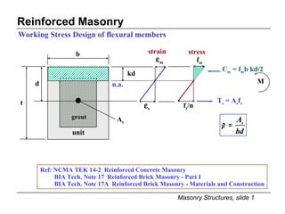
  • 1. Reinforced Masonry Working Stress Design of flexural members strain Ref: NCMA TEK 14-2 Reinforced Concrete Masonry BIA Tech. Note 17 Reinforced Brick Masonry - Part I BIA Tech. Note 17A Reinforced Brick Masonry - Materials and Construction T s = A s f s C m = f m b kd/2 M b d t A s grout unit n.a. kd f m f s /n stress
  • 2. Assumptions 1. plane sections remain plane after bending (shear deformations are neglected, strain distribution is linear with depth) 2. neglect all masonry in tension 3. stress-strain relation for masonry is linear in compression 4. stress-strain relation for steel is linear 5. perfect bond between reinforcement and grout (strain in grout is equal to strain in adjacent reinforcement) 6. masonry units and grout have same properties Reinforced Masonry Working Stress Design of flexural members
  • 3. Reinforced Masonry Working Stress Design of flexural members If f s =F s then moment capacity will be limited by reinforcement. Allowable reinforcement tensile stress per MSJC Sec.2.3.2: F s =20 ksi for Grades 40 or 50; F s =24 ksi for Grade 60 F s =30 ksi for wire joint reinforcement Allowable reinforcement tensile stress per UBC Sec.2107.2.11 : F s = 0.5 f y < 24 ksi for deformed bars; F s = 0.5 f y < 30 ksi for wire reinforcement F s = 0.4 f y < 20 ksi for ties, anchors, and smooth bars from equilibrium: where jd=d-kd/3 or j=1-k/3
  • 4. Reinforced Masonry Working Stress Design of flexural members If f m = F b then moment capacity will be limited by masonry. UBC 2107.2.6 & MSJC Sec.2.3.3.2: F b =0.33f’ m from equilibrium:
  • 5.
  • 6. WSD: Balanced Condition Reinforced Masonry from geometry: f s /n = F s /n d k b d f m = F b from equilibrium: C=T
  • 7. Example: Balanced Condition Determine the ratio of reinforcement that will result in a balanced condition per UBC. Given: f’ m = 2000 psi and Grade 60 reinforcement
  • 8. Design Strategy for RM Flexural Design Procedure for sizing section and reinforcement for given moment. Calculate  b knowing f’ m and f y determine F b from f’ m determine F s from f y determine E m from f’ m determine n = E s /E m Size section for some  b determine k and j bd 2 = M/  jF s select b and d using common units Size reinforcement A s = M/F s jd select number and size of rebars Check design M s = A s F s jd > M f b = M/0.5jkbd 2 < F b Note: Section must also be sized for shear.
  • 9. Example: Reinforced Masonry Design a beam section for a moment equal to 370 kip-in. Prisms have been tested and f’ m is specified at 2000 psi. Use Grade 60 reinforcement and 8” CMU’s.
  • 10. Example: Reinforced Masonry 5. Select dimensions of beam using 8” CMU’s: b = 7.63” d req’d = [4321 / 7.63] 0.5 = 23.8” use four units and center bars in bottom unit, d = 27.8” 4 - 8” CMU’s d=27.8” 7.63”
  • 11. Flexural Capacity of Partially Grouted Masonry Case A: neutral axis in flange * per MSJC Sec. 2.3.3.3 If kd < t f assumption is valid, determine moment capacity as for rectangular section. If kd > t f assumption is not valid , need to consider web portion. t t f A s per width b b = 6t or 72” or s * A s flange b d kd neutral axis If neutral axis is in flange, cracked section is the same as a solid rectangular section with width “b.” Therefore, depth to neutral axis from extreme compression fiber may be calculated using:
  • 12.
  • 13. Shear Design of Reinforced Masonry after cracking: V ext = V int = V s = nA v f s where n is the number of transverse bars across the diagonal crack. Assuming a 45 degree slope, n=d/s V s = (d/s)A v f s UBC Sec. 2107.2.17 (Eq. 7.38) MSJC Sec. 2.3.5.3 (Eq. 2-26)
  • 14. Shear Design of Reinforced Masomry Flexural shear stress f v b dx = dT = dM/jd f v = (dM/dx)/bjd dx UBC Sec. 2107.2.17 (Eq. 7-38) MSJC Sec. 2.3.5.2.1 (Eq. 2-19) M M + dM C jd T C + dC T + dT na T T + dT f v bdx
  • 15. Shear Design of Reinforced Masonry Allowable shear stresses for flexural members per UBC and MSJC UBC Sec. 2107.2.8.A and MSJC Sec. 2.3.5.2.2(a): members with no shear reinforcement UBC Eq. 7-17; MSJC Eq. 2-20 UBC Sec. 2107.2.8.B and MSJC Sec. 2.3.5.2.3(a): members with shear reinforcement designed to take the entire shear UBC Eq. 7-18; MSJC Eq. 2-23
  • 16. Shear Design of Reinforced Masonry Allowable shear stresses for shear walls per UBC and MSJC UBC Sec. 2107.2.9.i and MSJC Sec. 2.3.5.2.2(b): walls with in-plane flexural reinforcement and no shear reinforcement UBC Sec. 2107.2.9.ii and MSJC Sec. 2.3.5.2.3(b): walls with in-plane flexural reinforcement and shear reinforcement designed to take 100% of shear UBC Eq. 7-19; MSJC Eq. 2-21 UBC Eq. 7-21; MSJC Eq. 2-24 UBC Eq. 7-20; MSJC Eq. 2-22 UBC Eq. 7-22; MSJC Eq. 2-25
  • 17. Shear Design of Reinforced Masonry Moment-to-Shear Ratios d V M For a single-story cantilevered shear walls h V M M For piers between openings h d
  • 18. Shear Design of Reinforced Masonry MSJC Sec. 2.3.5.3.1 s max = d/2 or 48” d/2 V design Additional MSJC Requirements V design MSJC Sec. 2.3.3.4.2 minimum reinforcement perpendicular to shear reinforcement = A v /3 s max = 8 ft MSJC Sec. 2.3.5.5 design for shear force at distance “d/2” out from support
  • 19. Shear Design of Reinforced Masonry consider as unreinforced End Resize Section Determine F v Assuming Shear Reinforcement to take 100% of Shear Determine F v Assuming No Shear Reinforcement Determine Maximum Design Shear Shear Design Strategy for Reinforced Sections Determine Flexural Tension Stress f t = -P/A+Mc/I Start Provide Reinforcement to Take 100% of Shear Determine Shear Stress is f v <F v ? is f t >F t ? yes no is f v <F v ? no yes no yes
  • 20. Example: Design of RM Shear Wall Determine the maximum lateral force, H wind per UBC and MSJC 8” CMU wall Type S - PCL mortar solidly grouted f’ m =3000 psi #4 @ 32” 2 - #8’s each end of wall 6’-8” 6’-4” 8’-0” 120 psi Case A: neglect all reinforcement Case B: consider vertical reinf., neglect horizontal reinf. Case C: consider vertical and horizontal reinf. Case D: design horizontal reinforcement for max. shear
  • 21. Example: Design of RM Shear Wall Case A: neglect all reinforcement shear per UBC: flexure per MSJC: flexure shear
  • 22. Example: Design of RM Shear Wall Case B: consider only vertical reinforcement Shear per UBC Sec.2107.2.9 or MSJC Sec.2.3.5.2 Flexure by UBC or MSJC: neglecting f a lumping 2 - #8’s ave. d for 2 bars M s = A s F s jd = 2 x 0.79 in 2 (1.33 x 24 ksi) (0.9 x 72.0”) = 3268 k-in H wind = 34.0 kips
  • 23. Example: Design of RM Shear Wall Flexure by UBC or MSJC: same as case B Case C: consider all reinforcement Overall shear per UBC Sec. 2107.2.9.C or MSJC Sec. 2.3.5.2.3 (b) UBC MSJC V max = V s =(A v /s)F s d = (0.20 in 2 /32”)(24 ksi x 1.33)(72”) = 14.4 kips governs Shear per UBC Sec. 2107.2.17 or MSJC Sec.2.3.5.3
  • 24. Example: Design of RM Shear Wall Case D: design horizontal reinforcement for maximum shear strength Summary: H max, kips 10.2* 27.0 15.2 34.0* No steel vertical steel no horizontal steel vertical steel and #4 @ 32” horizontal steel #4 @ 8” horizontal 14.7* 24.3 15.2 34.0* Case A B C D Consideration UBC MSJC *flexure governs Case A B C D Consideration UBC MSJC No steel 14.7* 10.2* vertical steel no horizontal steel 23.0 25.6 vertical steel and #4 @ 32” horizontal steel 14.4 14.4 #4 @ 8” horizontal 34.0* 34.0*
  • 25. Flexural Bond Stress M = Tjd M + dM = (T + dT)jd dM = dT jd dT = dM/jd allowable bond stress per UBC Sec.2107.2.2.4: 60 psi for plain bars 200 psi for deformed bars 100 psi for deformed bars w/o inspection dx U T T + dT dx M C C + dC T jd T + dT M + dM dx dx U = bond force per unit length for group of bars U dx = dT = dM/jd U = (dM/dx)/jd = V/jd u = flexural bond stress = where sum of perimeters of all bars in group UBC Sec. 2107.2.16 Eq. 7-36
  • 27. Embedment of Flexural Reinforcement UBC Sec. 2106.3.4 and MSJC Sec.2.1. 8.3 Rule #1: extend bars a distance of “d” or “12d b ” past the theoretical cutoff point Rule #2: extend bars a distance of “l d ” past the point of maximum stress theoretical cutoff point capacity with bars “a” Moment Diagram moment capacity with bars “a” and “b” (#1) d or 12d b (#2) > l d (#2) > l d bars “b” bars “a” Example for shear wall:
  • 28. Combined Bending and Axial Loads Code Requirements UBC Sec. 2.14.2 if h’/t >30 then analysis should consider effects of deflections on moments MSJC Sec. 2.3.3.2.2 f a + f b < 1/3 f’ m provided that f a < F a In lieu of approximate method, use an axial-force moment interaction diagram. UBC Sec. 2107.1.6.3 use unity formula to check compressive stress: UBC Sec. 2107.1.6.1 P f a = P/A e Note: unity formula is conservative - better approach is to use P-M interaction diagram. M UBC Sec. 2107.2.15 A s f s jd kd
  • 29.
  • 30. Axial Force-Moment Interaction Diagram Range “a”: large P, small M, e=M/P < t/6 C m f m2 f m1 Out-of-Plane Bending of Reinforced Wall unit width = b e m P a = 0.5(f m1 + f m2 )A M a = 0.5(f m1 - f m2 )S where S = bt 2 /6 M b P a d = t/2
  • 31. Axial Force-Moment Interaction Diagram Out-of-Plane Bending of Reinforced Wall f m1 unit width = b Range “b” medium P, medium M, e > t/6 , A s in compression d = t/2 0.5 <  < 1.0 for section with reinforcement at center e m C m P b M b
  • 32. Axial Force-Moment Interaction Diagram Out-of-Plane Bending of Reinforced Wall Range “c” small P, large M, e > t/6 , A s in tension  < 0.5 for section with reinforcement at center unit width = b d = t/2 f m1 e m C m T s M c P c
  • 33. Axial Force-Moment Interaction Diagram f s < F s f m1 = F b f s = F s f m1 < F b Out-of-Plane Bending of Reinforced Wall e=0; M=0 f m1 = f m2 =F a P=F a A Start Stop Determine P and M per Range “b” Reduce f m2 from 2F a -F b by increment Determine P & M per Range “a” Determine P and M per Range “c” f s < F s ? M = 0? f m2 = 0? no yes is A s in tension? no yes Reduce  from 1.0 by increment Range “b” Range “a” f m1 = F b = f’ m /3 Reduce  from 0.5 by increment Range “c” no no yes tension controlling compression controlling yes
  • 34. Axial Force-Moment Interaction Diagram Out-of-Plane Bending of Reinforced Wall Axial Force F b Range “b” f m2 = 2F a - F b f m1 = F a f m1 = F b Range “a” F b F b F a limit by unity formula e 1 f s = F s F s /n f m Moment tension controls Range “c” balanced point F s /n F b compression controls f s /n F b
  • 35. Example: Interaction Diagram Determine an axial force-moment interaction diagram for a fully grouted 8” block wall reinforced with #4 @ 16”. Prism compressive strength has been determined by test to be equal to 2500 psi. Reinforcement is Grade 60. Height of wall is 11.5 feet.
  • 36. Example: Interaction Diagram Case f m1 (psi)  C m (kips) f m2 (psi) e m (in.) T s (kips) P=C m - T s (kips) M=C m e m (kip-in) 9 for P = 0: M m = 0.5F b jkbd 2 = 0.5(833 psi)(0.909)(0.272)(12)(3.81) 2 = 17.9 Range 2 833 417 - 57.2 - - 57.2 24.1 3 833 0 - 38.1 1.27 - 38.1 48.4 5 833 - 0.50 19.1 2.54 - 19.1 48.5 7 833 - 0.25 9.5 3.18 2.0 7.5 30.2 8 833 - 0.167 6.4 3.39 3.9 2.5 21.5 11 664* - 0.150 4.6 3.43 3.6 1.0 15.7 4 833 - 0.75 28.6 1.91 - 28.6 54.5 b 12 check for P = 0: M s = A s F s jd = (0.15 in 2 )(24 ksi)(0.909)(3.81”) = 12.5 1 625 625 - 57.2 0 - 57.2 0 a Compression Controls 6 833 - 0.33 12.6 2.97 0.9 11.7 37.4 10 833 bal. - 0.175 6.7 3.37 3.6 3.1 22.5 c Tension Controls *masonry stress inferred from F s and 
  • 37. Example: Interaction Diagram Axial Force kips 50 40 30 20 10 10 20 30 40 50 Moment, kip-in 1 12 10 10 833 3.6 k = A s F s 0.175t 11 11 664 3.6 k = A s F s 0.15t 1 625 417 2 833 2 0 3 833 3 4 833 .75t 4 5 833 0.50t 5 6 833 0.9k 0.33t 6 7 833 2.0 k 0.25t 7 8 8 833 3.9 k > A s F s 0.167t 9
  • 38. Flexural Capacity with Axial Compression Short Cut Method Out-of-Plane Bending, Reinforcement at Center stress compatibility: [1] d T s C m jd M P kd f s /n f m d [2] [3]
  • 39. Flexural Capacity with Axial Compression equilibrium: Short Cut Method [4] [5] [6] [7] [8] [9] [10] [11] [12]
  • 40. Strength Design of Reinforced Masonry Ultimate Flexural Strength A s t b Note: rectangular stress block can represent compressive stress distribution if k 2 /k 1 = 0.5 stresses C m M n T s = A s f y strains c n.a. d d f’ m f m c k 3 f’ m k 2 c C m c k 2 c C m = k 1 k 3 f’ m bc k l c k 3 f’ m =
  • 41. Strength Design of Reinforced Masonry Measuring k 1 k 3 and k 2  increase P 1 so that  = 0 P 0 +P 1 stress k 2 c k 3 f’ m k 1 c summing moments about centroid: P 1 a = (P o + P 1 )g = (P o + P 1 )(c/2 - k 2 c) total compressive force: P o + P 1 = k 3 f’ m k 1 cb a P o in displacement control P 1 in force control P o P 1 strain c g
  • 42. Strength Design of Reinforced Masonry Sample experimentally determined constants k 1 k 3 , and k 2 0 0.2 0.4 0.6 0.8 1 0 0.001 0.002 0.003 0.004 0.005 0.006 Extreme Fiber Strain (in/in) K1K3 & K2 K1K3 K2 Measured k 1 k 3 and k 2 values
  • 43. Strength Design of Reinforced Masonry Ultimate Flexural Strength f s summing moments about C m f y equilibrium
  • 44. Strength Design of Reinforced Masonry Balanced condition with single layer of reinforcement d strains c n.a. stresses k 1 c C m T s = A s f y M n strain compatibility equilibrium
  • 45. Strength Design of Reinforced Masonry f’ m Grade 40 Grade 60 Balanced condition with single layer of reinforcement 1000 0.0124 0.0062 0.0036 0.0071 2000 0.0247 0.0124 0.0143 0.0072 3000 0.0371 0.0186 0.0214 0.0107 4000 0.0495 0.0247 0.0285 0.0142 5000 0.0619 0.0309 0.0356 0.0178 6000 0.0742 0.0371 0.0428 0.0214
  • 46. Strength Design of Reinforced Masonry Balanced condition with multiple layers of reinforcement c A sbal b strain compatibility equilibrium strains d 4 d 3 d 2 d 1 0.85c stresses 0.85f’ m C s1 C m =0.85f’ m b(0.85c) C s2 T s3 T s4 = A sbal f y
  • 47. Example: Flexural Strength of In-Plane Wall Maximum steel is equal to one-half of that resulting in balanced conditions. f ’m = 1500 psi Grade 60 reinforcement special inspection Determine the maximum bar size that can be placed as shown. A sbal ? 7.63” 5’-4” T s3 T s4 = A sbal f y P n = 0 C s2 C s1 C m = 0.85f’ m b(0.85c) 0.85f’ m 60.0” c n.a. 0.003 4.0” 44.0” 20.0”
  • 48. Example: Flexural Strength of In-Plane Wall c = 0.003/0.00507 (60.0”) = 35.5” C m = 0.85f’ m b(0.85c) = -0.85(1500)(7.63”)(0.85 x 35.5) = -294 k Determine the maximum bar size. layer d i  si f si with compression steel (include C s1 and C s2 forces) C m +  (C si + T si ) = -294 + A sbal (-60.0 - 38.0 + 20.8 + 60.0) = 0 A sbal = -17.1 in 2 note: negative A sbal means that  C >  T , in such case no limit on tensile reinforcement 1 4.0” -0.00261 (C) -60.0 2 20.0” -0.00131 (C) -38.0 3 44.0” 0.00072 (T) 20.8 4 60.0” 0.00207 (T) 60.0 *bars larger than #9 are not recommended because of anchorage and detailing problems without compression steel (neglect C s1 andC s2 forces) C m +  (C si + T si ) = -294 + A sbal (20.8+ 60.0) = 0 A sbal = 3.64 in 2 A smax = 1.82 in 2 max. bar size is #ll (1.56 in 2 )*
  • 49. Example: Flexural Strength of In-Plane Wall Determine flexural strength of wall. 7.63” 5’-4” f ’m = 1500 psi Grade 60 reinforcement special inspection #8 (typ) 44.0” 20.0” 4.0” 60.0” c n.a. 0.003 T s4 = A s f y = 0.79 in 2 x 60 ksi = 47.4 k 0.85f’ m T s3 T s2 C s1 C m = 0.85f’ m b(0.85c)
  • 50. Example: Flexural Strength of In-Plane Wall c d 1 = 4.0” f 1 C sl d 2 = 20.0” f 2 T s2 d 3 = 44.0” f 3 T s3 C m Determine flexural strength of wall. -0.00240 -60 -47.4 0 0 0 0.00360 60.0 47.4 20.0 -165 -117.6 c 85 . 0 in kip 222 , 5 ) 89 . 4 0 . 60 )( 4 . 47 ( ) 89 . 4 0 . 44 )( 4 . 47 ( ) 89 . 4 0 . 20 )( 4 . 47 ( ) 89 . 4 00 . 4 )( 8 . 44 ( )} 2 d ( f A { M i si si n               15.0 -0.00220 -60 -47.4 0.00100 29.0 22.9 0.00580 60.0 47.4 -124 -54 11.0 -0.00191 -55 -43.7 0.00245 60.0 47.4 0.00900 60.0 47.4 -91 +7.5 close to zero, take c = 11.5” 11.5 -0.00196 -56 -44.8 0.00222 60.0 47.4 0.00848 60.0 47.4 -95 +2.3
  • 51. Example: Flexural Strength of In-Plane Wall Approximate flexural strength of wall. 7.63” 5’-4” #8 (typ)
  • 52. UBC Sec. 2108.2.4 Limitations of Method: Slender Wall Design (a) for out-of-plane bending of solid, reinforced walls lightly stressed under gravity loads (c)  g = A s /bt < 0.5  bal Ref: NCMA TEK 14-11A Strength Design of Tall Concrete Masonry Walls (d) special inspection must be provided during construction (e) t > 6” Sec. 2108.1.3: Load factors (b) limited to:
  • 53. Required Flexural Strength: UBC Sec. 2108.2.4.4 Slender Wall Design e h P uf t P uw w u h 2 /8 transverse load w u (P uw + P uf ) u h/2 h/2 P  eccentric load P uf e/2 P uf e
  • 54. Slender Wall Design Design Considerations 2. strain compatibility 3.  mu = 0.003 4. f s = E s  s < f y 5. neglect masonry strength in tension 6. rectangular stress block, k 1 = 0.85, k 3 = 0.85 Design strength: Sec. 2108.2.4.4 Assumptions for ultimate flexural strength (Sec. 2108.2.1.2) 1. equilibrium Strength reduction factor: flexure  = 0.8 Sec. 2108.1.4.2.1
  • 55. Slender Wall Design Equivalent area of reinforcement, A e for single wythe construction reinforced at center: b A s d Eq. (8-24) flexural strength P u = C m - A s f y C m = P u + A s f y = A se f y T s = A s f y T s = A s f y P u P u c d a = 0.85c 0.85f’ m C m =0.85f’ m b(0.85c) C m
  • 56. Slender Wall Design Lateral Deflections M M y M cr M s  s  y  cr Modulus of Rupture, f r Eqs. 8-31, 32, 33 fully grouted partially grouted hollow unit 2-wythe brick for M s < M cr (8-28) for M s > M cr (note “kd” may be replaced by “c” for simplicity) M cr = f r S (8-29)
  • 57. Slender Wall Design Design Considerations Strength Criteria Serviceability Criteria
  • 58. Example: Slender Wall Design Determine the maximum wind load, w, per UBC and MSJC 8” CMU, partially grouted f’ m = 2000 psi, Grade 60 500 lbs/ft dead 200 lbs/ft live #4 @ 32” 20’-0” 3’-0” 3.5” P w
  • 59. Example: Slender Wall Design U = 0.75 (1.4D + 1.7L + 1.7W) Flexural Strength per UBC M u =  M n =  A se f y (d - a/2)=0.8(0.103in 2 )(60ksi)(3.81in - 0.302in/2)=18.1 kip-in
  • 60. Example: Slender Wall Design to avoid iteration, assume M max = M u Flexural Strength per UBC w u =22.7 psf for simplicity, use gross section even though partially grouted
  • 61. Example: Slender Wall Design Check Service Load Deflections per UBC
  • 62. Example: Slender Wall Design Maximum Wind Load per MSJC Determine I cr considering axial compression 1.25” #4 @ 32” d = 3.82”
  • 63. Example: Slender Wall Design Note: same wind load as by UBC slender wall design procedure. Should also check compressive stress with an axial force-moment interaction diagram Maximum Wind Load per MSJC
  • 64. Strength Design of RM Shear Walls UBC Sec. 2108.1.1: Strength procedure may be used as an alternative to Sec. 2107 for design of reinforced hollow-unit masonry walls. UBC Requirements UBC Sec. 2108.1.2: Special inspection must be provided during construction. Prisms should be tested or unit strength method should be used. B. gravity loading: U = 1.4D + 1.7E (12-3) C. wind loading: U = 0.75(1.4D + 1.7 L + 1.7W) (12-4) U = 0.9D + - 1.3W (12-5) D. earth pressure: U = 1.4D + 1.7L + 1.7H (12-6) B. shear 2. Design strength A. axial load and flexure (see next slide) 1. Required strength A. earthquake loading: U = 1.4 (D+L+E) (12-1) U = 0.9D + - 1.4E (12-2) UBC Sec.2108.1.3: Shear wall design procedure
  • 65. Strength Design of RM Shear Walls Definition of Balanced Axial Load, P b b L w C m = 0.85f’ m ba b d 0.85f’ m C s1 C s2 P b T s3 T s4 = A sbal f y c n.a.
  • 66. Strength Design of RM Shear Walls 3. Design assumptions (same as for Slender Wall Design Procedure, UBC Sec. 2108.2.1.2) 1. equilibrium UBC Requirements 2. strain compatibility 3.  mu  = 0.003 4. f s = E s  s < f y 5. neglect masonry tensile strength 6. use rectangular stress block, k 1 = 0.85, k 3 = 0.85 7. 1500 psi < f’ m < 4000 psi
  • 67. Strength Design of RM Shear Walls 2. for flexural failure mode M n > = 1.8 M cr for fully grouted wall M n > = 3.0 M cr for partially grouted wall 3. anchor all continuous reinforcement M  UBC Requirements 4. A s vertical > 1/2 A s horizontal 5. maximum spacing of horizontal reinforcement within plastic hinge region = 3t or 24” M cr M n > M cr ductile M n < M cr nonductile 4. Reinforcement per UBC Sec. 2108.2.5.2 1. minimum reinforcement 5. Axial strength (no flexure) P o = 0.85 f’ m (A c -A s ) + f y A s P u < =  (0.80)P o
  • 68. Strength Design of RM Shear Walls UBC Requirements A mv = net area of masonry wall section bounded by wall thickness and length of section in direction of shear 2. for walls limited by shear strength: 6. Shear Strength UBC Sec. 2108.2.5.5 1. maximum nominal shear: A mv L w V u t
  • 69. Strength Design of RM Shear Walls UBC Requirements h t 6. Shear Strength UBC Sec. 2108.2.5.5.2 (continued) A vertical plane A s horizontal A s f y h L w L w A s f y L w A s f y
  • 70. Strength Design of RM Shear Walls 6. Shear Strength UBC Sec. 2108.2.5.5: continued 3. for walls limited by flexural strength: UBC Requirements within hinge region, distance of L w above base: ( V u determined at L w /2 from base) above hinge region:
  • 71. Strength Design of RM Shear Walls 1. Provide boundary members when the extreme fiber strain exceeds 0.0015. Boundary Members: Sec.2108.2.5.6 UBC Requirements Section at Base of Wall > 3t wall centroid #3 @ 8” min. 0.0015 t  mu > 0.0015 2. The minimum length of boundary members shall be 3t. 3. Boundary members shall be confined with a minimum of #3 bars @ 8” spacing, or equivalent confinement to develop an ultimate compressive masonry strain equal to 0.006.
  • 72. Example: Strength Design Determine the maximum wind force, H, and design horizontal reinforcement to develop the wall flexural strength. Consider: zero vertical load and P dead = 40 kips and P live = 30 kips 7.63” 4 - #8’s 5’-4” H 10’-8” 8” concrete block, fully grouted Grade 60 reinforcement , f’ m = 1500 psi from previous example:
  • 73. Example: Strength Design U = 1.3W Shear Reinforcement (neglecting vertical force) shear design within L w (5’-4”) of base: shear design for top 5’-4” of wall:
  • 74. Example:Shear Wall Strength Design Confinement requirements for vertical reinforcement per Sec. 2108.2.5.6 Confinement Reinforcement (neglecting vertical force) 7.63” 5’-4” #8 M u = 4,439 kip-in. 11.5” 5.75”  0.0015 3t > 5.7”  0.003 #3 @ 8” bottom 8 courses Strain Diagram per Previous Example
  • 75. Example: Strength Design Case 1: P u = 0.75(1.4 x 40 + 1.7 x 30) = 80.3 kips perhaps maximum flexural capacity and critical for shear design Flexural Strength considering Vertical Loads Case 2: P u = 0.9(40) = 36.0 kips perhaps minimum flexural capacity and lowest H u capacity reduction factors Case 1: Case 2:
  • 76. Example: Strength Design Flexural Strength considering Vertical Loads 20.0 -0.00240 -60 -47.4 0 0 0 0.00360 60.0 47.4 -165 -118 6,983 15.0 -0.00220 -60 -47.4 0.00100 29.0 22.9 0.00580 60.0 47.4 -124 -54 6,126 16.8 -0.00229 -60 -47.4 0.00057 16.6 13.1 0.00185 53.8 42.5 -139 -83 6,463 13.1 -0.00208 -60 -47.4 0.00104 30.0 23.7 0.00708 60.0 47.4 -108 -37 5,794 d 1 = 4.0” d 2 = 20.0” d 3 = 44.0”   f  C s    f  T s    f  C s  C m P n M n (kips) (kip-in) (kips) (kips) (kips) (kips) (ksi) (ksi) (ksi)
  • 77. Example: Strength Design Flexural Strength considering Vertical Loads H u = 34.1 kips (Case 2) ~ 34.7 kips (w/o vertical force). Use same shear design as for first part of problem. M u = 4,365 kip-in. (Case 2) ~ 4,439 kip-in. (w/o vertical force). Use same boundary members as for first part of problem. Axial Compressive Force, kips 140 120 100 80 60 40 20 5500 6000 6500 7000 Moment, M n kip-in. Case 2 6450 kip-in. 80.3 kips 5820 kip-in. Case 1 36.0 kips Case 2: Case 1: