How to convert a spherical mirror to a paraboloid mirror
•
1 like•1,708 views

Astrology

Recommended
Recommended
More Related Content
What's hot
What's hot (20)
Viewers also liked
Viewers also liked (11)
Similar to How to convert a spherical mirror to a paraboloid mirror
Similar to How to convert a spherical mirror to a paraboloid mirror (20)
More from Trịnh Thanh Tùng
Recently uploaded
Recently uploaded (20)
How to convert a spherical mirror to a paraboloid mirror
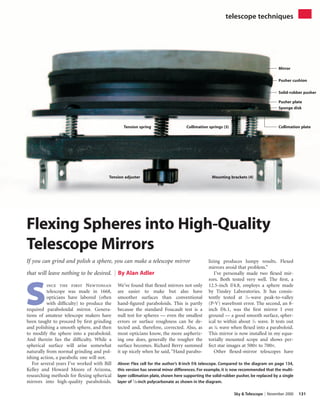
- 1. Sky & Telescope November 2000 131 S ince the first Newtonian telescope was made in 1668, opticians have labored (often with difficulty) to produce the required paraboloidal mirror. Genera- tions of amateur telescope makers have been taught to proceed by first grinding and polishing a smooth sphere, and then to modify the sphere into a paraboloid. And therein lies the difficulty. While a spherical surface will arise somewhat naturally from normal grinding and pol- ishing action, a parabolic one will not. For several years I’ve worked with Bill Kelley and Howard Moore of Arizona, researching methods for flexing spherical mirrors into high-quality paraboloids. We’ve found that flexed mirrors not only are easier to make but also have smoother surfaces than conventional hand-figured paraboloids. This is partly because the standard Foucault test is a null test for spheres — even the smallest errors or surface roughness can be de- tected and, therefore, corrected. Also, as most opticians know, the more aspheriz- ing one does, generally the rougher the surface becomes. Richard Berry summed it up nicely when he said, “Hand parabo- lizing produces lumpy results. Flexed mirrors avoid that problem.” I’ve personally made two flexed mir- rors. Both tested very well. The first, a 12.5-inch f/4.8, employs a sphere made by Tinsley Laboratories. It has consis- tently tested at 1 ⁄10-wave peak-to-valley (P-V) wavefront error. The second, an 8- inch f/6.1, was the first mirror I ever ground — a good smooth surface, spher- ical to within about 1 ⁄22 wave. It tests out as 1 ⁄40 wave when flexed into a paraboloid. This mirror is now installed in my equa- torially mounted scope and shows per- fect star images at 500× to 700×. Other flexed-mirror telescopes have Flexing Spheres into High-Quality Telescope Mirrors If you can grind and polish a sphere, you can make a telescope mirror that will leave nothing to be desired. By Alan Adler Above: Flex cell for the author’s 8-inch f/6 telescope. Compared to the diagram on page 134, this version has several minor differences. For example, it is now recommended that the multi- layer collimation plate, shown here supporting the solid-rubber pusher, be replaced by a single layer of 1 ⁄2-inch polycarbonate as shown in the diagram. telescope techniques Mirror Pusher cushion Solid-rubber pusher Collimation plateCollimation springs (3) Tension adjuster Mounting brackets (4) Tension spring Pusher plate Sponge disk ©2000 Sky Publishing Corp. All rights reserved.
- 2. 132 November 2000 Sky & Telescope telescopetechniques been made by Bill Kelley (who did the pioneering work), Howard Moore, and Sky & Telescope’s Gary Seronik. We be- lieve flexed mirrors offer such great po- tential that they will eventually become the first choice for high-quality reflecting telescopes. Flexed-mirror Origins Bill Kelley first wrote about flexing mir- rors in the June 1992 issue of Sky & Tele- scope (page 684). Kelley’s method was simple — he tensioned a steel stud glued to the center of the mirror back. I had read his article but my first “eyes-on” ex- posure was at the 1998 Riverside Tele- scope Maker’s Conference (RTMC). I was on the awards committee, and we judged a 13-inch f/6 telescope built by Kim Hyatt of Salt Lake City, Utah, that had a flexed mirror. I was intrigued by the concept and returned to the scope that evening to view some double stars. In only fair seeing the images in his flexed-mirror scope seemed about as sharp as those in a nearby scope of similar size that had a paraboloidal mirror made by a highly regarded custom maker. At the awards-committee meeting the next day I argued passionately that Kel- ley’s concept was the most important de- velopment in telescope making since the invention of the Dobsonian mount. My colleagues didn’t quite agree, but they did deem it worthy of an award. If I had known then what I know now about flexed mirrors, I would have argued even more passionately. Soon after RTMC I wrote a computer program to calculate the flexed-mirror shapes and ray-trace them. A major contribution came from Charles Steele, professor of mechanical engineering at Stanford University. He supplied an algo- rithm to analyze the flex of mirrors hav- ing variations in thickness that are a nat- ural result of a spherical front combined with either a flat or curved back. My program revealed that Kelley’s flex method deflected the center zones too deeply in order to pull the critical outer zones into the proper shape. I then sub- stituted an annular puller ring in place of the original center-pull and the program showed about a fivefold improvement in image quality — a very exciting develop- ment. I subsequently improved the figure even more by using a wide, sponge-rub- ber puller. The rubber distributed the tension uniformly over a broad region of the mirror back and yielded a further fivefold improvement in the accuracy of the mirror shape. By this time I was even more excited. The annular puller pro- duced a 25-fold improvement in image quality over Kelley’s original flex method. Image Evaluation My PC program, Flex, and instructions for use are available for downloading from the Sky & Telescope Web site at www.skypub.com/resources/software/ flex.html. This program will calculate the optimum puller dimensions, tension, and tolerances and display the resulting image quality and other data. Flex computes the geometric spot ratio for telescope mirrors. This is the intensity-weighted spot diameter divided by the Airy-disk diameter. A spot ratio of 1.0 corresponds approximately to Ray- leigh’s criterion for a 1 ⁄4-wave “diffraction- limited” telescope. In excellent seeing, critical observers can see errors down to about half of the Rayleigh tolerance, which corresponds to a spot ratio of 0.5. Further reductions in error are probably not visually detectable. Dividing the spot ratio by 4 gives a good estimate of the P-V wavefront error. But the spot ratio is really a better figure of merit than wavefront error — in any event, minimizing one also mini- mizes the other. As is clear from the plot on page 133, the sphere with the annular puller has the potential to form exquisite star images at the telescope’s focal plane. You needn’t figure a perfect sphere ei- ther. Any smooth, zone-free curve that is An overview of Adler’s high-performance 8- inch f/6 Newtonian, which features a spheri- cal primary mirror flexed into a superb pa- raboloid. Except where noted, all illustrations are courtesy the author. Bill Kelley (left) and Alan Adler met early this year with S&T associate editor Gary Seronik at Kel- ley’s Arizona home to discuss details of flex-mirror-cell designs.Adler’s work builds upon Kelley’s pioneering efforts, which first appeared in the June 1992 issue of Sky & Telescope. S&T:GARYSERONIK ©2000 Sky Publishing Corp. All rights reserved.
- 3. Sky & Telescope November 2000 133 approximately spherical can flex into a good paraboloid. The preferred depar- ture from a sphere would be deeper (to- ward a paraboloid). That would reduce total flex and thus reduce the chance of astigmatism. But I’ve even flexed an oblate mirror into a 1 ⁄17-wave paraboloid. An interesting application for micro- flex methods would be to improve the figure of undercorrected commercial pa- raboloids. Undercorrection is very com- mon, and just a slight amount of tension could produce great improvements. The flex cell also offers a good way to secure the mirror in your scope. Many small or slow commercial mir- rors are unparabolized spheres. This is particularly true for the ubiquitous im- ported 41 ⁄2-inch telescope mirrors that have substantially undercorrected figures even as perfect spheres. If they are rea- sonably smooth spheres, these mirrors can be easily flexed to create paraboloids of very high quality. The biggest hurdle to clear with flexed-mirror designs is astigmatism. To avoid it, the mirror must have very uni- form edge thickness. In other words, it must have very little wedge. The allow- able wedge is proportional to the f/ratio cubed, so that longer f/ratios have much greater tolerance. For example, an f/4 mirror can tolerate only 0.0017 inch of wedge, while an f/8 mirror can have a maximum of 0.014 inch of wedge. I found dewedging my 8-inch mirror to be surprisingly easy. It took about 40 minutes of accentuated pressure over the high side with 220 grit to take the wedge down to 0.0004 inch. –30 –20 –10 1 2 3 4 5 Zonalradius(inches) 0 Transverse ray error (microns) Airy-disk size Unflexed sphere Center pull Optimum annular pull +30+20+10 This plot shows the deviations of rays con- verging at the focal plane of a 10-inch f/6 spherical mirror mounted three different ways. Note the high quality of the sphere with the annular pull. Mirrors made this way have the potential to surpass the best paraboloids achievable by skilled opticians. Advertisement ©2000 Sky Publishing Corp. All rights reserved.
- 4. Design and Construction Details Look closely at the diagram at right. De- signing your own flex cell is mainly an exercise in determining the dimensions of the various pieces. The cell is simple, but there are a number of important points to keep in mind. First, a warning: Speed kills. When it comes to flexed paraboloids, fast mirrors are very demanding. I strongly recom- mend that your first project be f/6 or slower. Download Flex and play around with the various parameters. You will discover that short-focus mirrors not only require high puller tension but also have minuscule error budgets. The simplest approach that will yield excellent results is to use an annular pull- er and a flat-backed mirror blank. The best thickness ratio for the mirror blank is about 1:10. This gives the best figure and a good balance between stability and ease of flex. The traditional ratio of 1:6 is fine for f/8 and slower but requires too much tension for faster mirrors. To design an annular puller to match your mirror, you can run Flex or calcu- late the puller’s inner and outer diame- ters with these formulas: Puller inner diameter = (0.09 × D2 )/(T × f), Puller outer diameter = D × (0.97 – T/D), where D is the mirror’s diameter, T is its thickness, and f is its f/ratio. For example, the puller for a 10-inch- diameter f/6 mirror with a blank thickness of 1.0 inch would have an inner diameter of 1.5 inches [(0.09 × 10² )/(1 × 6)] and an outer diameter of 8.7 inches [10 × (0.97 – 1/10)]. I recommend a perimeter pusher cushion 1 ⁄2 inch wide and a gap between the pusher and puller of 1 ⁄4 inch or more. This might mean that you need a puller outside diameter slightly smaller than what you calculated using the formulas above. If so, use the smaller diameter — the paraboloid will still be excellent. The flex cell’s coil spring sta- bilizes the tension and prevents major changes in figure due to creep in the sponge rubber. I rec- ommend a spring that compresses between 1 ⁄2 and 1 inch at the de- sired tension. I’ve purchased all my springs from McMaster-Carr (562-692-5911, www.mcmaster. com). They have a large catalog of stock springs that generally cost less than $5. When it comes to the flex structure it- self, all materials must be isotropic — they must have the same stiffness in all direc- tions. Metal and unreinforced plastics are reasonably isotropic. Wood, plywood, and fabric-reinforced plastics are not isotropic and must be avoided. Medium density fiberboard (MDF), particleboard, and paper-phenolic are quasi-isotropic, and if the stress level is low, these materi- als should perform acceptably. The flex cell for my 12.5-inch f/4.8 is made from MDF. With this or any other porous material it’s recommended that you first paint the bond surfaces to avoid excessive absorption of the adhesive (dis- cussed later) and possible adhesive de- pletion in the bond line. Painting all sur- faces also reduces moisture absorption and reduces the chances of warping. Despite my own success with MDF, others have found that their flex cells produced astigmatic images. For this rea- son I recommend that you make your cell from aluminum and/or polycarbonate plastic. I used both for my 8-inch, and not only was the cell easier to make but the resulting mirror is completely astig- matism free. Polycarbonate is the best choice of plastics. It is isotropic, widely available, free from creep (long-term de- formation), and it resists cracking. A lathe or a router provides the easiest way to make the parts very round. If nei- ther is available, use a saber saw or band saw and cut the best circle you can. Small bumps or notches in the circles will not affect the figure of the flexed mirror, but large variations creating ellipses or egg-shaped parts will cause astigmatism. The rubber used for the pusher and puller must have uniform thickness and density. The puller rubber must also be suitable for adhesive bonding. I tested sponge, solid rubbers, and adhe- sives by bonding them between metal blocks and measuring the force required to pull them apart. Many of the sponge materials I tested had treated surfaces that did not bond well. My best re- sults were with Neoprene/EPDM/ SBR sponge rubber, a 1 ⁄2-inch- thick, firm grade, 42-inch-wide 134 November 2000 Sky & Telescope telescopetechniques The author’s software, Flex, allows users to investigate the performance of a given flexed mirror and calculates the rec- ommended dimensions for the various flex-cell components. Shown here is the output for Adler’s 8-inch f/6 mirror. Mirror Knob 3/8”puller sponge 1/2”puller plate 1/2” solid- rubber pusher Saw slot 1/4”collimation screws (3) Collimation springs (3) Threaded inserts (3) 2”spring Scope wall 1/4-20 × 4”carriage bolt3/8”hole 3/4”MDF plate 3/8”puller sponge 1/2”puller plate 1/2”collimation plate (polycarbonate) After two years of research, the author arrived at this design for flexing spherical mirrors into precise paraboloids. The assembly also provides the necessary collimation adjustments. The holes for the collimation screws must be oversize to permit them to float without applying torque to the pusher.This is essential to avoid introducing astigmatism. ©2000 Sky Publishing Corp. All rights reserved.
- 5. Sky & Telescope November 2000 135 sheet, McMaster-Carr part number 8647K46. The sheets are overly wide but, fortunately, this material is sold by the foot. One foot is enough for any tele- scope smaller than 12 inches in aperture. For the lower half of the pusher side- walls I recommend solid rubber instead of sponge. Use high-grade Neoprene rubber, 1 ⁄2-inch thick, 40A durometer, 12- inch-square sheet, with McMaster-Carr part number 8568K517. The upper half of the pusher must be sponge rubber. To glue the various pieces together it’s best to use an adhesive that cures to a semiflexible state. It is also important that the cure rate be slow enough to allow for even spreading. I evaluated many adhesives, and to date the only ac- ceptable one I’ve found is 3M Scotch- Weld Urethane Adhesive 3549 (3M Cor- poration, 800-362-3550). This is a two-part adhesive, which is absolutely es- sential to ensure that it completely cures in the center of the bonded area. Before you glue the pieces together, the surfaces should be properly prepared. The adhesive must bond fully across all contact surfaces. I could easily write an entire article on surface preparation for adhesive bonding, but suffice it to say that you want to be sure your bond sur- face doesn’t come into contact with oils, waxes, soaps, or anything slippery. Begin by lightly sanding the rubber or plastic surfaces prior to bonding and brush away the sanding dust. A small amount of leftover dust is okay since it will be absorbed into the adhesive layer like a particulate filler. Next, clean the glass and metal surfaces with acetone. Make sure your rag or paper towel is very clean and oil free. Do not touch the prepared surfaces with your bare skin. Now you’re ready to begin building the flex cell. Some Assembly Required The first step is to glue the sponge to the puller plate. Cut the sponge diameter about 11 ⁄2 inches oversize without a hole in the center. Mix more glue than you think you need. The suggested bead length is about the diameter of the piece squared, divided by 6. For example, an 8-inch-diameter piece would need a bead length of 8 squared divided by 6, or about 10 inches long for each of the two adhesive parts. Mix the glue thor- oughly and spread it very uniformly on both surfaces with a toothed-edge glue spreader. Next, put the sponge disk (glue Advertisement ©2000 Sky Publishing Corp. All rights reserved.
- 6. Spot Ratios for Three Flex Methods Center pull Annular pull Full-diam. pull Diameter† F/ratio (flat back) (flat back) (spherical back) 6 8 0.30 0.005 0.004 6 6 0.78 0.04 0.011 8 8 0.43 0.01 0.009 8 6 1.03 0.04 0.02 12 5 * 0.14 0.03 16 5 * 0.17 0.03 20 4 * 0.55 0.05 30 4 * 0.99 0.12 †All mirrors have 1:10 thickness ratios. * Not recommended — spot ratio exceeds 1.0. 136 November 2000 Sky & Telescope Some Alternative Ways to Flex a Mirror A lthough the flex design discussed in the main article pro- vides the simplest way to achieve high-quality results, there are several different ways to microflex a mirror. Center Pull with Flat Back This is Bill Kelley’s original concept. For small mirrors or large f/ratios it’s quite good; however, as the table at right indicates, it is not recommended for large and/or fast mirrors. Annular Pull with Flat Back This is the method described in the main article and is the best choice for amateur telescope makers. It gives excellent images with mirrors up to about 20 inches in diameter. Full-Diameter Pull with Convex Spherical Back Convex back curvature further improves the image quality. For moderate-size mirrors the improvement is beyond visual de- tectability. But with large and/or very fast mirrors, convex backs are very desirable. The best radius of back curvature is approxi- mately equal to the front-surface radius. With convex backs it’s best to pull on the entire back — leaving only a small outer band for edge support. The puller plate should be figured con- cave to mate to the back through an intervening rubber layer. These methods (except as noted) result in mirrors that are es- sentially perfect for visual use. But despite the good theoretical figure of large, fast mirrors it remains to be proved that they can be flexed without introducing astigmatism.Two other flex meth- ods offer great promise: center pull with an optimum-shaped back and vacuum pull. With optimum back shape, a center pull can theoretically give a near-perfect image.The diagram at left shows the cross section of the optimum center-pull shape for a 10-inch f/6 mirror.This shape could be machined on a diamond lathe; it cannot be hand ground. Vacuum pull is another interesting possibility. Any large-area puller must have uniform tension to avoid astigmatism. Vacuum pull is certainly uniform, and I have experimented with it. However I’ve achieved excellent figure with a bonded rubber puller so the complexity of a vacuum system may not be justified. side up!) on a flat surface and the puller plate on top and pile about 20 pounds of weight on it. The weight should be well centered to avoid wedging the glue line. The puller plate will begin floating sideways. By taping three sticks to the sponge to capture the puller plate, you can prevent this lateral drift. A bead of glue should soon appear all around the edge. An important charac- teristic of this adhesive is that it sets slowly, allowing time for it to ooze out and form a uniform layer. If you don’t see the bead appear within five minutes around the full circumference of the puller plate, you don’t have enough glue. Pull the pieces apart and add more. Let the parts set overnight. Once the glue has completely cured, use a razor blade to trim the edge of the sponge flush and square with the outside diameter of the puller plate. Finish the job with 100-grit sandpaper on a small block. The rubber should be square with the edge of the puller and perfectly round where it bonds to the mirror. Roundness is essential to avoid astigma- tism. If the edge gets slightly out of square, sand around the full circumfer- ence at a uniform angle — just make sure the face that will be glued to the mirror is perfectly round and concentric with the puller plate. Drill out the center of the sponge, using the hole in the center of the puller plate as a guide. Make a cardboard tem- plate and mark the specified inside di- ameter of the puller (a white ballpoint pen is handy for this). Cut through the Left: Flexed mirrors made with the optimum-shaped back shown here have the potential to yield near-perfect images. Unlike conventional telescope mirrors, the glass blanks used for flexed mirrors must be rela- tively free of wedge — variations in the uniformity of edge thickness. This simple wedge tester, built by Kelley, uses a $10 dial gauge to measure a mirror blank that is supported at three points and butted up against a pair of posts. Rotate the mirror 30° between readings. S&T:GARYSERONIK Center-pull attachment point Rubber bond Mirror ©2000 Sky Publishing Corp. All rights reserved.
- 7. Sky & Telescope November 2000 137 sponge on this line, taking care to keep the knife-edge perpendicular to the puller face. Tear off the center sponge as best you can. You needn’t remove every bit; just ensure that none of the central area will be in contact with the mirror when they are glued together. Make sure that the area immediately surrounding the central hole is free of rubber so that there is a clean seat for the carriage bolt. Although the method described above works well, the best way to trim the outer edge and relieve the center area is with a lathe. Gluing to the Mirror This is the stage at which many of us slipped up in our first attempts at mak- ing flexed-mirror systems. The mistake was allowing the puller to float off center while the glue set. It is absolutely essential to prevent that. Make three precise cen- tering blocks (see the illustrations at the top of the next page) and test them be- fore applying glue to ensure that they hold the puller plate snug and perfectly centered on the back of the mirror. Apply masking tape to the outer por- tion of the mirror back. Then trim it to a perfectly centered circle, exactly match- ing the outside diameter of the puller sponge. Next, apply masking tape to the edge of the puller sponge too. The mask- ing tape will prevent these surfaces from getting contaminated with glue, which will stiffen when set and possibly intro- duce astigmatism. At this point insert the carriage bolt in the puller plate and secure it with a nut. (I once assembled a puller and forgot to insert the bolt! This is a mistake you will definitely want to avoid.) The bolt also serves as a convenient handle for holding the puller while you are spreading glue. I used a clean piece of 1 ⁄8-inch-thick posterboard for my gluing platform. I placed the mirror face down and attached the three centering blocks to the board with double-sided carpet tape. After meas- uring and testing for centering I added some paper shims to get a snug fit. Now, as before, spread the glue evenly and make sure some oozes out the edge to verify that you have used enough. Lay weights on top and allow the assembly to set for about 24 hours. I used counter- weights from my German equatorial mount to apply about 20 pounds of force while the adhesive cured. The holes in the counterweights conveniently clear the puller bolt. Advertisement ©2000 Sky Publishing Corp. All rights reserved.
- 8. After 24 hours remove the masking tape and trim off the excess glue with a sharp blade. Make certain that the mirror back is clean and free of any lumps that might come into contact with the pusher. It’s tempting to consider applying heat to hasten the cure, but this would prevent the slow ooze of the glue that provides uniform distribution. However, a moder- ate (150° Fahrenheit) post cure for a few hours is desirable once the glue has set. The heat polymerizes the glue and makes it stronger and more creep-resistant. Tolerances on centering can be taken from the “pusher uniformity” specifica- tion in the Flex program. For example, an 8-inch f/6 has a uniformity tolerance of 1.2 percent. This means that this pusher assembly can tolerate a decenter- ing of 0.096 inch. However, that’s your entire error budget, and you won’t want to squander all of it with decentering. Nonuniformity of puller or pusher rub- ber, decentering of the mirror on the pusher ring, wedge, voids in the glue, and a host of other potential problems will also eat into this error budget. All Newtonian telescopes, including those with flexed mirrors, require colli- mation adjustment. It is most important to ensure that any stresses that might arise from collimation are not trans- ferred to the flexed mirror, where they would show up as astigmatism. The fig- ure on page 134 shows my design, which allows for precise collimation and does not introduce astigmatism. The polycar- bonate collimation plate bears against the pusher plate through an intervening layer of sponge rubber. One similar mir- ror had a plywood collimation plate that warped. Again, use isotropic materials only — plywood must be avoided. In the Field Although Flex will tell you how much tension you need to apply, how do you know if you are applying the correct amount? Bill Kelley views a star through a Ronchi grating (without an eyepiece) and adjusts his scope’s tension until he sees straight Ronchi bands. Although quick and easy, this test appears to be limited to about a 1 ⁄4-wave adjustment ac- curacy. Gary Seronik and I have found that it’s easy to achieve greater precision by adjusting tension while star testing — checking for matching defocused star images on either side of focus. Adding a temporary cardboard disk to the spider hub (to create a 33 percent obstruction) makes this test even more sensitive. Once the optimum tension has been found, the spring length can be meas- ured with a micrometer and noted so that you can easily repeat the tension set- ting in the future. The tolerance for the tension adjust- ment is surprisingly broad. For moderate f/ratio mirrors the tension can vary by 15 percent before image degradation (over- correction or undercorrection) is de- tectable. The slower the focal ratio, the less critical the tension. Gravity can also cause small changes in puller tension for large mirrors. But if the tension is set when the scope is aimed at 60° altitude, tension will increase by half the mirror weight at the zenith and decrease by the same amount at the horizon. The resulting variations in image quality will be too small to detect visually. Many people have asked me if I leave my mirror under tension when it’s not in use. With my first (12.5-inch) flexed mir- ror, I reduced tension by half when it 138 November 2000 Sky & Telescope telescopetechniques One of the most critical stages of flex-cell construction is gluing the puller plate to the sponge rubber and then gluing this to the back of the mirror. In the image at left, the three wood blocks and paper shims keep the puller assembly accurately centered on the back of the mirror while the glue sets. After 24 hours have passed (right), the masking tape can be peeled away, leaving a clean, well-bonded puller assembly. The flex-mirror cell installed in the author’s 8- inch telescope.The large knob at center is the tension adjustment. The collimation screws labeled X and Y tilt the mirror in two planes perpendicular to one another. Masking tape Wood blocks Paper shims Posterboard Telescope counterweight Double-backed carpet tape ©2000 Sky Publishing Corp. All rights reserved.
- 9. Sky & Telescope November 2000 139 was not in use because I was concerned about the long-term strength of the sponge rubber. However, I’ve left full tension on my 8-inch mirror since com- pleting it in April. Initially, I tested the mirror every few days. During the first couple of weeks the figure tended to creep back from a 1 ⁄20-wave setting to about 1 ⁄4 wave in a couple of days. But as the sponge rubber settled in, the figure began to stabilize. Now I rarely touch the adjustment. Having good optics greatly height- ened my awareness of thermal problems. Indeed, the finest mirror in the world will mostly disappoint if thermal issues are not addressed. Observing regularly with my flexed-mirror 8-inch, I learned to differentiate between exterior seeing problems and internal thermals. (See S&T: September, page 125.) With good optics and good seeing I found that at 500× the Airy disk appears crisply de- fined despite internal thermals — the thermals simply caused the star images to occasionally flare or double. After many experiments I installed a small fan in the side of the tube blowing right across the front of the mirror to exhaust holes on the opposite side. When turned on, this fan cleans up the image in seconds. Final Thoughts So what about big mirrors? As men- tioned previously, the greatest challenge has been to flex a mirror without intro- ducing astigmatism. This is much more difficult to achieve with large and/or fast mirrors, which require greater amounts of flex than smaller ones. If you experi- ment with the Flex software you will find that large, fast mirrors of excellent figure are theoretically possible — especially if they have spherical back surfaces. How- ever, the largest mirrors flexed to date have been 121 ⁄2-inch. I think that a pneu- matic perimeter cushion offers the best promise of providing the extremely uni- form pressure essential for large and/or fast flexed mirrors, but this remains to be demonstrated. In addition to yielding moderate-size Newtonian optics of remarkable quality, microflexed mirrors offer exciting possi- bilities for advances in compound tele- scopes. You can make a wide range of aspheric reflectors by selecting puller tension, puller dimensions, and back curvature. When combined with other optical elements, these aspheric reflectors could enhance Maksutovs, Cassegrains, and other compound systems, including Newtonians with field correctors or focal reducers. I am currently assisting a friend in designing a hyperbolic astrograph with a flexed mirror. Perhaps even en- tirely new types of telescopes will be made possible once the talents of other ATMs are unleashed. As the tension of the flex cell is adjusted toward optimum, the focus position changes slightly, but the image grows increasingly sharp.Some tweaking may be needed for a few weeks until the flex cell becomes “broken in.” 1/4 –40% –20% 0% Tension variation P-Vwavefronterror(λ) 1 2 Turns of tension on adjustment knob 3 +20% +40% 1/5 1/7 1/10 1/20 Advertisement ©2000 Sky Publishing Corp. All rights reserved.
- 10. Since making this flexed-mirror scope, I have enjoyed many stunning views. I would not have believed that a simple 8- inch Newtonian was capable of such ex- cellence. At 500× to 700× close doubles are “refractor perfect” — two sharp dots surrounded by sharply defined diffrac- tion rings. The biggest surprise so far has been the appearance of globular clusters. I had always thought spectacular views of these objects were the sole property of large-aperture scopes. But the view of M13 in my 8-inch is so sharp that all who have seen it agree that it’s as good as it gets. Since I finished my scope in April, Northern California has been blessed with an unusually high number of nights with excellent seeing. That has permitted many experienced amateurs to test my scope at 500× and higher. Their exclama- tions of “Wow!” and “Unbelievable!” have been music to my ears. Alan Adler has about 70 U.S. and foreign patents in diverse fields ranging from opto- electronics to flying toys. His best-known in- vention is the Aerobie flying ring, which holds the Guinness world record for the farthest human-thrown object. He is a lecturer in me- chanical engineering at Stanford University. Patents are pending on microflex mirrors. Par- ties interested in commercial applications should contact the author regarding a license. 140 November 2000 Sky & Telescope For the author, having a high-quality mirror underscored the need to address thermal problems. Seen here is his solution. A 3-inch fan blows directly across the face of the mir- ror toward exhaust holes (visible in the view at bottom on page 138) on the opposite side. This setup greatly reduces the image flare and doubling that result from heat radiating from the primary mirror. Advertisement ©2000 Sky Publishing Corp. All rights reserved.