Build, program and modify an electronic compass
•Télécharger en tant que DOCX, PDF•
1 j'aime•1,213 vues

This I My Senior Project Presentation at Devry University, this Project/Presentation recieved a grade of 100.

Recommandé
Recommandé
Contenu connexe
Similaire à Build, program and modify an electronic compass
Similaire à Build, program and modify an electronic compass (20)
Dernier
Dernier (9)
Build, program and modify an electronic compass
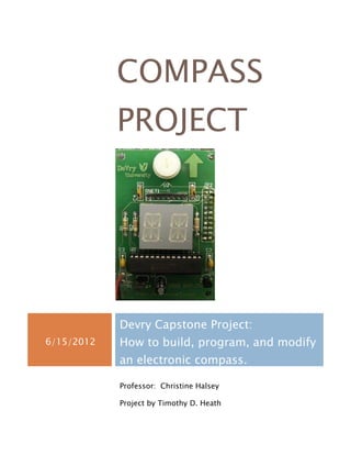
- 1. COMPASS PROJECT Devry Capstone Project: 6/15/2012 How to build, program, and modify an electronic compass. Professor: Christine Halsey Project by Timothy D. Heath
- 2. Compass Project This document is intended to explain how to assemble a compass circuit kit, program the pic16f72 chip, and modify the circuit board, and program resulting ina fully functional compass. TABLE OF CONTENTS Introduction …………………………………………………………… pg2 Hardware List a. Compass kit b. Computer c. Eblock EB006 programmer board with power supply d. USB A/B male cable e. 9v battery Software List a. PPP V.3 PIC micro programmer b. Flowcode Project Description………………………………………………pg2 , pg3 1|Page
- 3. Compass Project Assembly and Initial programming a. Compass kit- b. Flowcode c. PPPv3 Modifications a. Hardware Modifications b. Software Modifications Conclusion…………………………………………………………… pg 4 Compass Project DEVRY CAPSTONE PROJECT: HOW TO BUILD, PROGRAM, AND MODIFY AN ELECTRONIC COMPASS. Introduction The compass kit is ordered form Devry bookstore, upon delivery all parts were accounted for. The kit has a compass module that changes resistance depending on orientation to magnetic north. The signal from the module is then controlled by the program in the picf72 microchip. After the program has executed a signal is sent to the appropriate LED light’s on the display. Page 2
- 4. Compass Project Hardware List a. Compass kit b. Computer c. Eblock EB006 programmer board with power supply d. USB A/B male cable e. 9v battery Software List a. PPP V.3 PIC micro programmer b. Flowcode Project Description Assembly and Initial programming a. Compass kit- the compass kit needs to have all components soldered onto the circuit board. No schematic is supplied. Student must assemble with information given which is a parts list and picture of completed board. Additionally my professor added videos of how to get compass module easily installed. I made a mistake and installed JP2 connector to the top of the circuit board when it should have been installed on the bottom. The JP2 connects the compass circuit to the EB006 programmer. That mistake cost me a lot of time and I actually damaged several traces on circuit board while correcting this problem. The damage had to be fixed by soldering an extra wire for each of the broken traces. I would suggest to anyone assembling this kit to double check each component before soldering begins. b. Flowcode-was accessed through Citrix platform and a working program is available in Doc Sharing tab of course. The original program needs to be compiled to .hex before it can be used by programming software. c. PPPv3-I had enormous difficulty getting the correct driver installed and functioning properly. I went to Matrix Multimedia web site and manually tried each driver until I found one that worked with a 64bit system. I still had further difficulties getting the computer to recognize the EB006 board and picf72chip on board compass circuit. These problems were eventually fixed through trial and error. The problem would not let me go the normal route defined in the 3|Page
- 5. Compass Project course description of installation. After resolving problems the process is simple take the Hex file created in flowcode, select the appropriate chip from the expert menu, then download program to chip. Modifications a. Hardware Modifications- This was fairly simple 3 connections were missing from circuit board. This was listed on the supplied circuit diagram for the pic16f72 as pin 11,13, and 14 were labled NC(not connected). These three pins correspond to port C0,C1, and C2. The LED display also has 3 pins not connected pin 4, 14, and 15. These unconnected pins on display correspond to LED M, J, and K. I remedied this problem by soldering the wires onto the circuit board as follows: PIC Display 11pin 4pin 13pin 15pin 14pin 14pin b. Software Modifications- The software modifications were requested to change the display from its original program of N-E-S-W to an arrow that always points north. This modification requires the program to be altered by changing which LED’s are lit up on the display for each respective direction. The display has ports of PIC program (ports B0-B7 and ports C0-C7) that correspond to each segment of display which is designated as a letter (A B C D E F g1 H g2 J K L M N) . A truth table makes quick work of figuring out which port goes to what segment. The following truth table is a partial representation of how I programmed the segments to light up. b7 b6 b5 b4 b3 b2 b1 B0 F H E N G1 A L g2 W1 1 1 1 1 O O O Page 4
- 6. Compass Project N0 0 0 1 0 0 1 0 S0 0 0 0 0 1 0 0 C7 C6 C5 C4 C3 C2 C1 C0 D C C1 C2 J K B M W0 0 0 0 0 0 0 0 N1 0 0 0 0 0 0 1 Conclusion After completing this project I feel more confident in building, programming, and modifying a circuit. Of course these things I have already learned from my own experiences, and previous courses I have completed at Devry. What I more importantly take away from this class project is improved ability to clearly explain and demonstrate both process and progress of technical information. 5|Page