SlideShare a Scribd company logo
1 of 65
Now we have understood,
 For any signal to be considered as logic ‘0’ and logic ‘1’, it should be in the NML and
 NMH ranges, respectively


3/2/2013                                                                                   1
Now we have understood,
 For any signal to be considered as logic ‘0’ and logic ‘1’, it should be in the
 NML and NMH ranges, respectively


  Now, let us understand the factors affecting the voltage levels to vary from this range
3/2/2013                                                                              2
Ideal
                                                                       Switching
                                                                        Activity


                                                                              Actual
                                                                             Switching
                                                                              Activity


Switching Activity of a Device is one of the factors which affects the voltage levels of
Input/Output signals
Vdd


                          Poly Gate
                                             PMOS – P Diff

                     In                            Out

                                              NMOS – N Diff


                                          Vss


Lets understand the internal process while Switching Activity happens in a Device
Vdd


                         Poly Gate
                                            PMOS – P Diff

                    In                           Out

                                            NMOS – N Diff


                                         Vss


               PMOS                                          NMOS
Consider the MOS device, to understand the actual scenario
PMOS                                         NMOS


   Let’s revise MOS device characteristics
MOS device characteristics


                                                             G

                                                     Vgs


                                                 S                D
                                                           NMOS


                    Vgs is the Voltage between gate and source
MOS device characteristics


            G

    Vgs


S                     D
          NMOS
MOS device characteristics


            G

    Vgs
                                    Vgs < VT (Threshold Voltage)
                                                                   S                  D

S                     D
          NMOS


                      If Vgs   is   less then VT , the NMOS will act as Open Switch
MOS device characteristics


            G

    Vgs
                                    Vgs > VT (Threshold Voltage)
                                                                   S                   D

S                     D
          NMOS


                      If Vgs   is   greater then VT , the NMOS will act as Closed Switch
MOS device characteristics


            G

    Vgs                              Vgs > VT

                                 S              D

S                     D
          NMOS
MOS device characteristics


               G

    Vgs                                                                 Vgs > VT

                                               S                                   D

S                        D
             NMOS

          When MOSFET is ‘ON’, it can be modeled as a ‘Resistor’ with switch closed

          When MOSFET is ‘OFF’, it can be modeled as an ‘open switch’
When MOSFET is ‘ON’, it can be modeled as a ‘Resistor’ with closed switch
When MOSFET is ‘ON’, it can be modeled as a ‘Resistor’ with switch closed


PMOS acts as Logic ‘0’                        NMOS acts as Logic ‘1’
When MOSFET is ‘ON’, it can be modeled as a ‘Resistor’ with switch closed


PMOS acts as Logic ‘0’                        NMOS acts as Logic ‘1’
When MOSFET is ‘OFF’, it can be modeled as an ‘open switch’
When MOSFET is ‘ON’, it can be modeled as a ‘Resistor’ with switch closed


 PMOS acts as Logic ‘0’                        NMOS acts as Logic ‘1’
 When MOSFET is ‘OFF’, it can be modeled as an ‘open switch’


       PMOS                                          NMOS

PMOS acts as Logic ‘1’                        NMOS acts as Logic ‘0’
Vdd


In                      Out


               Vss


     Input Switching from logic ‘1’ to logic ‘0’
Vdd


In                      Out


               Vss


     Input Switching from logic ‘1’ to logic ‘0’

     NMOS is turning ‘OFF’
Vdd


In                      Out


               Vss


     Input Switching from logic ‘1’ to logic ‘0’

     NMOS is turning ‘OFF’

     PMOS is turning ‘ON’
Input Switching from logic ‘1’ to logic ‘0’

NMOS is turning ‘OFF’
Input Switching from logic ‘1’ to logic ‘0’

NMOS is turning ‘OFF’

PMOS is turning ‘ON’
Input Switching from logic ‘1’ to logic ‘0’

            NMOS is turning ‘OFF’

            PMOS is turning ‘ON’


     Vdd


In         Out


     Vss
Input Switching from logic ‘1’ to logic ‘0’

                              NMOS is turning ‘OFF’

                              PMOS is turning ‘ON’


                    Vdd                                   Vdd


                                                      R

In                          Out                                   Out


                    Vss                                   Vss


     Replace PMOS as resistor and NMOS by open switch.
Input Switching from logic ‘1’ to logic ‘0’

                         NMOS is turning ‘OFF’

                         PMOS is turning ‘ON’


                 Vdd                                   Vdd


             R                                     R

                       Out                                             Out

                                                                 CL


                 Vss                                   Vss


Connect Capacitor on output end.
Input Switching from logic ‘1’ to logic ‘0’

                             NMOS is turning ‘OFF’

                             PMOS is turning ‘ON’


              Vdd


          R

                             Out

                        CL


              Vss


Consider Capacitor is charged when Vdd is applied.
Input Switching from logic ‘1’ to logic ‘0’

                            NMOS is turning ‘OFF’

                            PMOS is turning ‘ON’


              Vdd


          R

                            Out

                       CL


              Vss


Consider Capacitor is charged up to Vdd
Input Switching from logic ‘1’ to logic ‘0’

               NMOS is turning ‘OFF’

               PMOS is turning ‘ON’


    Vdd


R

               Out

          CL


    Vss
Summary


     Vdd                 Vdd


                     R

In         Out                      Out

                               CL


     Vss                 Vss
Summary


                                                    Vdd


                                                R

                                                                   Out

                                                              CL


                                                    Vss


Lets convert the area within dotted lines into closed loop circuit.
Summary


                                                   Vdd


       R                                       R

                                                              Out
Vdd                   CL
                                                         CL


                                                   Vss


      Lets convert into closed loop circuit.
Summary


                         Capacitor Models


      R


Vdd       CL
Summary


                                  Capacitor Models


      R            Uncharged Cap           +
                                             0V             short
                                           -

Vdd       CL
                                           +                +
                    Charged Cap              V                VO
                                           - O              -


                                           +
                  Fully Charged Cap          Open circuit
                                           -
Summary


                         Waveforms


      R


Vdd       CL
Summary


                               Waveforms


                         Vdd

      R


Vdd       CL
Summary


                               Waveforms


                         Vdd

      R

                         VCL
Vdd       CL
Summary


                               Waveforms


                         Vdd

      R

                         VCL
Vdd       CL

                         VR
Summary


                               Waveforms


                         Vdd

      R

                         VCL
Vdd       CL

                         VR


                                  I = V/R
Summary


                               Waveforms


                         Vdd

      R

                         VCL
Vdd       CL

                         VR


                                  I = V/R

                         IR
Summary


                                 Waveforms


                           Vdd

      R

                           VCL
Vdd       CL

                           VR


                                    I = V/R
                   Ipeak
                           IR
So what can we conclude!!!


A capacitor needs at least Ipeak amount of current
So what can we conclude!!!


A capacitor needs at least Ipeak amount of current


Ipeak
        IR
So what can we conclude!!!


A capacitor needs at least Ipeak amount of current


Ipeak
        IR


               To get charged upto Vdd voltage
So what can we conclude!!!


A capacitor needs at least Ipeak amount of current


Ipeak
        IR


               To get charged upto Vdd voltage


             VCL
So what can we conclude!!!


A capacitor needs at least Ipeak amount of current


Ipeak
        IR


               To get charged upto Vdd voltage


             VCL


And, the output of inverter, is recognized as logic ‘1’
So what can we conclude!!!


A capacitor needs at least Ipeak amount of current


Ipeak
        IR


               To get charged upto Vdd voltage


             VCL


And, the output of inverter, is recognized as logic ‘1’
And, the output of inverter, is recognised as logic ‘1’


             What does this mean????
And, the output of inverter, is recognised as logic ‘1’


                   What does this mean????


     It means that the voltage across capacitor

     Vpeak
             VCL
And, the output of inverter, is recognised as logic ‘1’


                   What does this mean????


     It means that the voltage across capacitor

     Vpeak
             VCL


        Lies in NMH level of noise margin graph
Vdd
VOH
            NMH
VIH         Noise Margin High


                                NMH = VOH - VIH

                                NML = VIL - VOL

VIL         NML
            Noise Margin High
VOL

      0
Why to do?


3/2/2013                65

More Related Content

What's hot (20)

Eco
EcoEco
Eco
 
Low Power VLSI Design
Low Power VLSI DesignLow Power VLSI Design
Low Power VLSI Design
 
Spi master core verification
Spi master core verificationSpi master core verification
Spi master core verification
 
Design challenges in physical design
Design challenges in physical designDesign challenges in physical design
Design challenges in physical design
 
Vlsi technology-dinesh
Vlsi technology-dineshVlsi technology-dinesh
Vlsi technology-dinesh
 
Understanding cts log_messages
Understanding cts log_messagesUnderstanding cts log_messages
Understanding cts log_messages
 
Physical Verification Design.pdf
Physical Verification Design.pdfPhysical Verification Design.pdf
Physical Verification Design.pdf
 
Multi mode multi corner (mmmc)
Multi mode multi corner (mmmc)Multi mode multi corner (mmmc)
Multi mode multi corner (mmmc)
 
Low power sram
Low power sramLow power sram
Low power sram
 
Signal Integrity (SI glitch)
Signal Integrity (SI glitch)Signal Integrity (SI glitch)
Signal Integrity (SI glitch)
 
CMOS Logic Circuits
CMOS Logic CircuitsCMOS Logic Circuits
CMOS Logic Circuits
 
Inputs of physical design
Inputs of physical designInputs of physical design
Inputs of physical design
 
Powerplanning
PowerplanningPowerplanning
Powerplanning
 
Physical design
Physical design Physical design
Physical design
 
Need of Decoupling Capacitor
Need of Decoupling CapacitorNeed of Decoupling Capacitor
Need of Decoupling Capacitor
 
Single Ended Schmitt Trigger Based Robust Low Power SRAM Cell
Single Ended Schmitt Trigger Based Robust Low Power SRAM CellSingle Ended Schmitt Trigger Based Robust Low Power SRAM Cell
Single Ended Schmitt Trigger Based Robust Low Power SRAM Cell
 
Low Power Techniques
Low Power TechniquesLow Power Techniques
Low Power Techniques
 
Static Timing Analysis
Static Timing AnalysisStatic Timing Analysis
Static Timing Analysis
 
Power Gating
Power GatingPower Gating
Power Gating
 
Routing.ppt
Routing.pptRouting.ppt
Routing.ppt
 

Viewers also liked

Floorplan (http://www.vlsisystemdesign.com/PD-Flow.php)
Floorplan (http://www.vlsisystemdesign.com/PD-Flow.php)Floorplan (http://www.vlsisystemdesign.com/PD-Flow.php)
Floorplan (http://www.vlsisystemdesign.com/PD-Flow.php)VLSI SYSTEM Design
 
Define location of Preplaced cells(http://www.vlsisystemdesign.com/PD-Flow.php)
Define location of Preplaced cells(http://www.vlsisystemdesign.com/PD-Flow.php)Define location of Preplaced cells(http://www.vlsisystemdesign.com/PD-Flow.php)
Define location of Preplaced cells(http://www.vlsisystemdesign.com/PD-Flow.php)VLSI SYSTEM Design
 
Define Width and Height of Core and Die (http://www.vlsisystemdesign.com/PD-F...
Define Width and Height of Core and Die (http://www.vlsisystemdesign.com/PD-F...Define Width and Height of Core and Die (http://www.vlsisystemdesign.com/PD-F...
Define Width and Height of Core and Die (http://www.vlsisystemdesign.com/PD-F...VLSI SYSTEM Design
 
Time saver project template
Time saver project templateTime saver project template
Time saver project templateKim Cao
 
E sky2u.com marketing plan v3.0
E sky2u.com marketing plan v3.0E sky2u.com marketing plan v3.0
E sky2u.com marketing plan v3.0e-sky, Inc
 
BÍ QUYẾT QUẢN LÝ HIỆU QUẢ CÂU LẠC BỘ CHA MẸ VÀ VỊ THÀNH NIÊN, THANH NIÊN
BÍ QUYẾT QUẢN LÝ HIỆU QUẢ CÂU LẠC BỘ CHA MẸ VÀ VỊ THÀNH NIÊN, THANH NIÊNBÍ QUYẾT QUẢN LÝ HIỆU QUẢ CÂU LẠC BỘ CHA MẸ VÀ VỊ THÀNH NIÊN, THANH NIÊN
BÍ QUYẾT QUẢN LÝ HIỆU QUẢ CÂU LẠC BỘ CHA MẸ VÀ VỊ THÀNH NIÊN, THANH NIÊNCGFED
 
Financial aid assistance
Financial aid assistanceFinancial aid assistance
Financial aid assistancelupitacm
 
CCP's Mishu System Tsai and Dean
CCP's Mishu System Tsai and DeanCCP's Mishu System Tsai and Dean
CCP's Mishu System Tsai and DeanSAINBAYAR Beejin
 
Comment Letter on New Regulations Addressing BDPOs -- Letter dated January 3,...
Comment Letter on New Regulations Addressing BDPOs -- Letter dated January 3,...Comment Letter on New Regulations Addressing BDPOs -- Letter dated January 3,...
Comment Letter on New Regulations Addressing BDPOs -- Letter dated January 3,...Samuel Grilli
 
Show me your hands
Show me your handsShow me your hands
Show me your handsTerry Penney
 
Case study: #GoogleMoLang
Case study: #GoogleMoLangCase study: #GoogleMoLang
Case study: #GoogleMoLangnoreensayoc
 
International trade course 3
International trade course 3International trade course 3
International trade course 3Yudy Yunardy
 

Viewers also liked (20)

Floorplan (http://www.vlsisystemdesign.com/PD-Flow.php)
Floorplan (http://www.vlsisystemdesign.com/PD-Flow.php)Floorplan (http://www.vlsisystemdesign.com/PD-Flow.php)
Floorplan (http://www.vlsisystemdesign.com/PD-Flow.php)
 
Place decap
Place decapPlace decap
Place decap
 
Define location of Preplaced cells(http://www.vlsisystemdesign.com/PD-Flow.php)
Define location of Preplaced cells(http://www.vlsisystemdesign.com/PD-Flow.php)Define location of Preplaced cells(http://www.vlsisystemdesign.com/PD-Flow.php)
Define location of Preplaced cells(http://www.vlsisystemdesign.com/PD-Flow.php)
 
Define Width and Height of Core and Die (http://www.vlsisystemdesign.com/PD-F...
Define Width and Height of Core and Die (http://www.vlsisystemdesign.com/PD-F...Define Width and Height of Core and Die (http://www.vlsisystemdesign.com/PD-F...
Define Width and Height of Core and Die (http://www.vlsisystemdesign.com/PD-F...
 
Low power vlsi design
Low power vlsi designLow power vlsi design
Low power vlsi design
 
Time saver project template
Time saver project templateTime saver project template
Time saver project template
 
E sky2u.com marketing plan v3.0
E sky2u.com marketing plan v3.0E sky2u.com marketing plan v3.0
E sky2u.com marketing plan v3.0
 
BÍ QUYẾT QUẢN LÝ HIỆU QUẢ CÂU LẠC BỘ CHA MẸ VÀ VỊ THÀNH NIÊN, THANH NIÊN
BÍ QUYẾT QUẢN LÝ HIỆU QUẢ CÂU LẠC BỘ CHA MẸ VÀ VỊ THÀNH NIÊN, THANH NIÊNBÍ QUYẾT QUẢN LÝ HIỆU QUẢ CÂU LẠC BỘ CHA MẸ VÀ VỊ THÀNH NIÊN, THANH NIÊN
BÍ QUYẾT QUẢN LÝ HIỆU QUẢ CÂU LẠC BỘ CHA MẸ VÀ VỊ THÀNH NIÊN, THANH NIÊN
 
Financial aid assistance
Financial aid assistanceFinancial aid assistance
Financial aid assistance
 
Historia del computador
Historia del computadorHistoria del computador
Historia del computador
 
Transformator
TransformatorTransformator
Transformator
 
CCP's Mishu System Tsai and Dean
CCP's Mishu System Tsai and DeanCCP's Mishu System Tsai and Dean
CCP's Mishu System Tsai and Dean
 
How To Promote Your Business On Pinterest
How To Promote Your Business On PinterestHow To Promote Your Business On Pinterest
How To Promote Your Business On Pinterest
 
Primary EFL Reading Competition
Primary EFL Reading CompetitionPrimary EFL Reading Competition
Primary EFL Reading Competition
 
Comment Letter on New Regulations Addressing BDPOs -- Letter dated January 3,...
Comment Letter on New Regulations Addressing BDPOs -- Letter dated January 3,...Comment Letter on New Regulations Addressing BDPOs -- Letter dated January 3,...
Comment Letter on New Regulations Addressing BDPOs -- Letter dated January 3,...
 
NASA RFP
NASA RFPNASA RFP
NASA RFP
 
Show me your hands
Show me your handsShow me your hands
Show me your hands
 
Opjo
OpjoOpjo
Opjo
 
Case study: #GoogleMoLang
Case study: #GoogleMoLangCase study: #GoogleMoLang
Case study: #GoogleMoLang
 
International trade course 3
International trade course 3International trade course 3
International trade course 3
 

Similar to Understanding How Switching Activity Affects Logic Levels in Digital Circuits

MOS as Diode, Switch and Active Resistor
MOS as Diode, Switch and Active ResistorMOS as Diode, Switch and Active Resistor
MOS as Diode, Switch and Active ResistorSudhanshu Janwadkar
 
Digital ic ajal crc
Digital ic ajal crcDigital ic ajal crc
Digital ic ajal crcAJAL A J
 
Power mosfet characteristics
Power mosfet characteristicsPower mosfet characteristics
Power mosfet characteristicssanu singh
 
CMOS Topic 5 -_cmos_inverter
CMOS Topic 5 -_cmos_inverterCMOS Topic 5 -_cmos_inverter
CMOS Topic 5 -_cmos_inverterIkhwan_Fakrudin
 

Similar to Understanding How Switching Activity Affects Logic Levels in Digital Circuits (7)

MOS as Diode, Switch and Active Resistor
MOS as Diode, Switch and Active ResistorMOS as Diode, Switch and Active Resistor
MOS as Diode, Switch and Active Resistor
 
Transistor
TransistorTransistor
Transistor
 
IC_Lectures_Updated.pdf
IC_Lectures_Updated.pdfIC_Lectures_Updated.pdf
IC_Lectures_Updated.pdf
 
Pass Transistor Logic
Pass Transistor LogicPass Transistor Logic
Pass Transistor Logic
 
Digital ic ajal crc
Digital ic ajal crcDigital ic ajal crc
Digital ic ajal crc
 
Power mosfet characteristics
Power mosfet characteristicsPower mosfet characteristics
Power mosfet characteristics
 
CMOS Topic 5 -_cmos_inverter
CMOS Topic 5 -_cmos_inverterCMOS Topic 5 -_cmos_inverter
CMOS Topic 5 -_cmos_inverter
 

Recently uploaded

ISYU TUNGKOL SA SEKSWLADIDA (ISSUE ABOUT SEXUALITY
ISYU TUNGKOL SA SEKSWLADIDA (ISSUE ABOUT SEXUALITYISYU TUNGKOL SA SEKSWLADIDA (ISSUE ABOUT SEXUALITY
ISYU TUNGKOL SA SEKSWLADIDA (ISSUE ABOUT SEXUALITYKayeClaireEstoconing
 
AMERICAN LANGUAGE HUB_Level2_Student'sBook_Answerkey.pdf
AMERICAN LANGUAGE HUB_Level2_Student'sBook_Answerkey.pdfAMERICAN LANGUAGE HUB_Level2_Student'sBook_Answerkey.pdf
AMERICAN LANGUAGE HUB_Level2_Student'sBook_Answerkey.pdfphamnguyenenglishnb
 
Earth Day Presentation wow hello nice great
Earth Day Presentation wow hello nice greatEarth Day Presentation wow hello nice great
Earth Day Presentation wow hello nice greatYousafMalik24
 
Karra SKD Conference Presentation Revised.pptx
Karra SKD Conference Presentation Revised.pptxKarra SKD Conference Presentation Revised.pptx
Karra SKD Conference Presentation Revised.pptxAshokKarra1
 
MULTIDISCIPLINRY NATURE OF THE ENVIRONMENTAL STUDIES.pptx
MULTIDISCIPLINRY NATURE OF THE ENVIRONMENTAL STUDIES.pptxMULTIDISCIPLINRY NATURE OF THE ENVIRONMENTAL STUDIES.pptx
MULTIDISCIPLINRY NATURE OF THE ENVIRONMENTAL STUDIES.pptxAnupkumar Sharma
 
Influencing policy (training slides from Fast Track Impact)
Influencing policy (training slides from Fast Track Impact)Influencing policy (training slides from Fast Track Impact)
Influencing policy (training slides from Fast Track Impact)Mark Reed
 
4.18.24 Movement Legacies, Reflection, and Review.pptx
4.18.24 Movement Legacies, Reflection, and Review.pptx4.18.24 Movement Legacies, Reflection, and Review.pptx
4.18.24 Movement Legacies, Reflection, and Review.pptxmary850239
 
USPS® Forced Meter Migration - How to Know if Your Postage Meter Will Soon be...
USPS® Forced Meter Migration - How to Know if Your Postage Meter Will Soon be...USPS® Forced Meter Migration - How to Know if Your Postage Meter Will Soon be...
USPS® Forced Meter Migration - How to Know if Your Postage Meter Will Soon be...Postal Advocate Inc.
 
How to Add Barcode on PDF Report in Odoo 17
How to Add Barcode on PDF Report in Odoo 17How to Add Barcode on PDF Report in Odoo 17
How to Add Barcode on PDF Report in Odoo 17Celine George
 
Roles & Responsibilities in Pharmacovigilance
Roles & Responsibilities in PharmacovigilanceRoles & Responsibilities in Pharmacovigilance
Roles & Responsibilities in PharmacovigilanceSamikshaHamane
 
Keynote by Prof. Wurzer at Nordex about IP-design
Keynote by Prof. Wurzer at Nordex about IP-designKeynote by Prof. Wurzer at Nordex about IP-design
Keynote by Prof. Wurzer at Nordex about IP-designMIPLM
 
Proudly South Africa powerpoint Thorisha.pptx
Proudly South Africa powerpoint Thorisha.pptxProudly South Africa powerpoint Thorisha.pptx
Proudly South Africa powerpoint Thorisha.pptxthorishapillay1
 
ENGLISH 7_Q4_LESSON 2_ Employing a Variety of Strategies for Effective Interp...
ENGLISH 7_Q4_LESSON 2_ Employing a Variety of Strategies for Effective Interp...ENGLISH 7_Q4_LESSON 2_ Employing a Variety of Strategies for Effective Interp...
ENGLISH 7_Q4_LESSON 2_ Employing a Variety of Strategies for Effective Interp...JhezDiaz1
 
Difference Between Search & Browse Methods in Odoo 17
Difference Between Search & Browse Methods in Odoo 17Difference Between Search & Browse Methods in Odoo 17
Difference Between Search & Browse Methods in Odoo 17Celine George
 
Field Attribute Index Feature in Odoo 17
Field Attribute Index Feature in Odoo 17Field Attribute Index Feature in Odoo 17
Field Attribute Index Feature in Odoo 17Celine George
 
Gas measurement O2,Co2,& ph) 04/2024.pptx
Gas measurement O2,Co2,& ph) 04/2024.pptxGas measurement O2,Co2,& ph) 04/2024.pptx
Gas measurement O2,Co2,& ph) 04/2024.pptxDr.Ibrahim Hassaan
 
ECONOMIC CONTEXT - PAPER 1 Q3: NEWSPAPERS.pptx
ECONOMIC CONTEXT - PAPER 1 Q3: NEWSPAPERS.pptxECONOMIC CONTEXT - PAPER 1 Q3: NEWSPAPERS.pptx
ECONOMIC CONTEXT - PAPER 1 Q3: NEWSPAPERS.pptxiammrhaywood
 
ACC 2024 Chronicles. Cardiology. Exam.pdf
ACC 2024 Chronicles. Cardiology. Exam.pdfACC 2024 Chronicles. Cardiology. Exam.pdf
ACC 2024 Chronicles. Cardiology. Exam.pdfSpandanaRallapalli
 

Recently uploaded (20)

ISYU TUNGKOL SA SEKSWLADIDA (ISSUE ABOUT SEXUALITY
ISYU TUNGKOL SA SEKSWLADIDA (ISSUE ABOUT SEXUALITYISYU TUNGKOL SA SEKSWLADIDA (ISSUE ABOUT SEXUALITY
ISYU TUNGKOL SA SEKSWLADIDA (ISSUE ABOUT SEXUALITY
 
AMERICAN LANGUAGE HUB_Level2_Student'sBook_Answerkey.pdf
AMERICAN LANGUAGE HUB_Level2_Student'sBook_Answerkey.pdfAMERICAN LANGUAGE HUB_Level2_Student'sBook_Answerkey.pdf
AMERICAN LANGUAGE HUB_Level2_Student'sBook_Answerkey.pdf
 
Earth Day Presentation wow hello nice great
Earth Day Presentation wow hello nice greatEarth Day Presentation wow hello nice great
Earth Day Presentation wow hello nice great
 
Karra SKD Conference Presentation Revised.pptx
Karra SKD Conference Presentation Revised.pptxKarra SKD Conference Presentation Revised.pptx
Karra SKD Conference Presentation Revised.pptx
 
MULTIDISCIPLINRY NATURE OF THE ENVIRONMENTAL STUDIES.pptx
MULTIDISCIPLINRY NATURE OF THE ENVIRONMENTAL STUDIES.pptxMULTIDISCIPLINRY NATURE OF THE ENVIRONMENTAL STUDIES.pptx
MULTIDISCIPLINRY NATURE OF THE ENVIRONMENTAL STUDIES.pptx
 
Influencing policy (training slides from Fast Track Impact)
Influencing policy (training slides from Fast Track Impact)Influencing policy (training slides from Fast Track Impact)
Influencing policy (training slides from Fast Track Impact)
 
4.18.24 Movement Legacies, Reflection, and Review.pptx
4.18.24 Movement Legacies, Reflection, and Review.pptx4.18.24 Movement Legacies, Reflection, and Review.pptx
4.18.24 Movement Legacies, Reflection, and Review.pptx
 
USPS® Forced Meter Migration - How to Know if Your Postage Meter Will Soon be...
USPS® Forced Meter Migration - How to Know if Your Postage Meter Will Soon be...USPS® Forced Meter Migration - How to Know if Your Postage Meter Will Soon be...
USPS® Forced Meter Migration - How to Know if Your Postage Meter Will Soon be...
 
How to Add Barcode on PDF Report in Odoo 17
How to Add Barcode on PDF Report in Odoo 17How to Add Barcode on PDF Report in Odoo 17
How to Add Barcode on PDF Report in Odoo 17
 
Roles & Responsibilities in Pharmacovigilance
Roles & Responsibilities in PharmacovigilanceRoles & Responsibilities in Pharmacovigilance
Roles & Responsibilities in Pharmacovigilance
 
Keynote by Prof. Wurzer at Nordex about IP-design
Keynote by Prof. Wurzer at Nordex about IP-designKeynote by Prof. Wurzer at Nordex about IP-design
Keynote by Prof. Wurzer at Nordex about IP-design
 
FINALS_OF_LEFT_ON_C'N_EL_DORADO_2024.pptx
FINALS_OF_LEFT_ON_C'N_EL_DORADO_2024.pptxFINALS_OF_LEFT_ON_C'N_EL_DORADO_2024.pptx
FINALS_OF_LEFT_ON_C'N_EL_DORADO_2024.pptx
 
TataKelola dan KamSiber Kecerdasan Buatan v022.pdf
TataKelola dan KamSiber Kecerdasan Buatan v022.pdfTataKelola dan KamSiber Kecerdasan Buatan v022.pdf
TataKelola dan KamSiber Kecerdasan Buatan v022.pdf
 
Proudly South Africa powerpoint Thorisha.pptx
Proudly South Africa powerpoint Thorisha.pptxProudly South Africa powerpoint Thorisha.pptx
Proudly South Africa powerpoint Thorisha.pptx
 
ENGLISH 7_Q4_LESSON 2_ Employing a Variety of Strategies for Effective Interp...
ENGLISH 7_Q4_LESSON 2_ Employing a Variety of Strategies for Effective Interp...ENGLISH 7_Q4_LESSON 2_ Employing a Variety of Strategies for Effective Interp...
ENGLISH 7_Q4_LESSON 2_ Employing a Variety of Strategies for Effective Interp...
 
Difference Between Search & Browse Methods in Odoo 17
Difference Between Search & Browse Methods in Odoo 17Difference Between Search & Browse Methods in Odoo 17
Difference Between Search & Browse Methods in Odoo 17
 
Field Attribute Index Feature in Odoo 17
Field Attribute Index Feature in Odoo 17Field Attribute Index Feature in Odoo 17
Field Attribute Index Feature in Odoo 17
 
Gas measurement O2,Co2,& ph) 04/2024.pptx
Gas measurement O2,Co2,& ph) 04/2024.pptxGas measurement O2,Co2,& ph) 04/2024.pptx
Gas measurement O2,Co2,& ph) 04/2024.pptx
 
ECONOMIC CONTEXT - PAPER 1 Q3: NEWSPAPERS.pptx
ECONOMIC CONTEXT - PAPER 1 Q3: NEWSPAPERS.pptxECONOMIC CONTEXT - PAPER 1 Q3: NEWSPAPERS.pptx
ECONOMIC CONTEXT - PAPER 1 Q3: NEWSPAPERS.pptx
 
ACC 2024 Chronicles. Cardiology. Exam.pdf
ACC 2024 Chronicles. Cardiology. Exam.pdfACC 2024 Chronicles. Cardiology. Exam.pdf
ACC 2024 Chronicles. Cardiology. Exam.pdf
 

Understanding How Switching Activity Affects Logic Levels in Digital Circuits

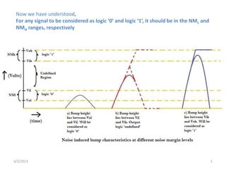
  • 1. Now we have understood, For any signal to be considered as logic ‘0’ and logic ‘1’, it should be in the NML and NMH ranges, respectively 3/2/2013 1
  • 2. Now we have understood, For any signal to be considered as logic ‘0’ and logic ‘1’, it should be in the NML and NMH ranges, respectively Now, let us understand the factors affecting the voltage levels to vary from this range 3/2/2013 2
  • 3. Ideal Switching Activity Actual Switching Activity Switching Activity of a Device is one of the factors which affects the voltage levels of Input/Output signals
  • 4. Vdd Poly Gate PMOS – P Diff In Out NMOS – N Diff Vss Lets understand the internal process while Switching Activity happens in a Device
  • 5. Vdd Poly Gate PMOS – P Diff In Out NMOS – N Diff Vss PMOS NMOS Consider the MOS device, to understand the actual scenario
  • 6. PMOS NMOS Let’s revise MOS device characteristics
  • 17. MOS device characteristics G Vgs S D NMOS Vgs is the Voltage between gate and source
  • 18. MOS device characteristics G Vgs S D NMOS
  • 19. MOS device characteristics G Vgs Vgs < VT (Threshold Voltage) S D S D NMOS If Vgs is less then VT , the NMOS will act as Open Switch
  • 20. MOS device characteristics G Vgs Vgs > VT (Threshold Voltage) S D S D NMOS If Vgs is greater then VT , the NMOS will act as Closed Switch
  • 21. MOS device characteristics G Vgs Vgs > VT S D S D NMOS
  • 22. MOS device characteristics G Vgs Vgs > VT S D S D NMOS When MOSFET is ‘ON’, it can be modeled as a ‘Resistor’ with switch closed
  • 23. MOS device characteristics G Vgs Vgs > VT S D S D NMOS When MOSFET is ‘ON’, it can be modeled as a ‘Resistor’ with switch closed When MOSFET is ‘OFF’, it can be modeled as an ‘open switch’
  • 24. When MOSFET is ‘ON’, it can be modeled as a ‘Resistor’ with closed switch
  • 25. When MOSFET is ‘ON’, it can be modeled as a ‘Resistor’ with switch closed PMOS acts as Logic ‘0’ NMOS acts as Logic ‘1’
  • 26. When MOSFET is ‘ON’, it can be modeled as a ‘Resistor’ with switch closed PMOS acts as Logic ‘0’ NMOS acts as Logic ‘1’ When MOSFET is ‘OFF’, it can be modeled as an ‘open switch’
  • 27. When MOSFET is ‘ON’, it can be modeled as a ‘Resistor’ with switch closed PMOS acts as Logic ‘0’ NMOS acts as Logic ‘1’ When MOSFET is ‘OFF’, it can be modeled as an ‘open switch’ PMOS NMOS PMOS acts as Logic ‘1’ NMOS acts as Logic ‘0’
  • 28. Vdd In Out Vss Input Switching from logic ‘1’ to logic ‘0’
  • 29. Vdd In Out Vss Input Switching from logic ‘1’ to logic ‘0’ NMOS is turning ‘OFF’
  • 30. Vdd In Out Vss Input Switching from logic ‘1’ to logic ‘0’ NMOS is turning ‘OFF’ PMOS is turning ‘ON’
  • 31. Input Switching from logic ‘1’ to logic ‘0’
  • 32. Input Switching from logic ‘1’ to logic ‘0’ NMOS is turning ‘OFF’
  • 33. Input Switching from logic ‘1’ to logic ‘0’ NMOS is turning ‘OFF’ PMOS is turning ‘ON’
  • 34. Input Switching from logic ‘1’ to logic ‘0’ NMOS is turning ‘OFF’ PMOS is turning ‘ON’ Vdd In Out Vss
  • 35. Input Switching from logic ‘1’ to logic ‘0’ NMOS is turning ‘OFF’ PMOS is turning ‘ON’ Vdd Vdd R In Out Out Vss Vss Replace PMOS as resistor and NMOS by open switch.
  • 36. Input Switching from logic ‘1’ to logic ‘0’ NMOS is turning ‘OFF’ PMOS is turning ‘ON’ Vdd Vdd R R Out Out CL Vss Vss Connect Capacitor on output end.
  • 37. Input Switching from logic ‘1’ to logic ‘0’ NMOS is turning ‘OFF’ PMOS is turning ‘ON’ Vdd R Out CL Vss Consider Capacitor is charged when Vdd is applied.
  • 38. Input Switching from logic ‘1’ to logic ‘0’ NMOS is turning ‘OFF’ PMOS is turning ‘ON’ Vdd R Out CL Vss Consider Capacitor is charged up to Vdd
  • 39. Input Switching from logic ‘1’ to logic ‘0’ NMOS is turning ‘OFF’ PMOS is turning ‘ON’ Vdd R Out CL Vss
  • 40. Summary Vdd Vdd R In Out Out CL Vss Vss
  • 41. Summary Vdd R Out CL Vss Lets convert the area within dotted lines into closed loop circuit.
  • 42. Summary Vdd R R Out Vdd CL CL Vss Lets convert into closed loop circuit.
  • 43. Summary Vdd R R Out Vdd CL CL Vss Lets convert into closed loop circuit.
  • 44. Summary Capacitor Models R Vdd CL
  • 45. Summary Capacitor Models R Uncharged Cap + 0V short - Vdd CL + + Charged Cap V VO - O - + Fully Charged Cap Open circuit -
  • 46. Summary Waveforms R Vdd CL
  • 47. Summary Waveforms Vdd R Vdd CL
  • 48. Summary Waveforms Vdd R VCL Vdd CL
  • 49. Summary Waveforms Vdd R VCL Vdd CL VR
  • 50. Summary Waveforms Vdd R VCL Vdd CL VR I = V/R
  • 51. Summary Waveforms Vdd R VCL Vdd CL VR I = V/R IR
  • 52. Summary Waveforms Vdd R VCL Vdd CL VR I = V/R Ipeak IR
  • 53. So what can we conclude!!!
  • 54. So what can we conclude!!! A capacitor needs at least Ipeak amount of current
  • 55. So what can we conclude!!! A capacitor needs at least Ipeak amount of current Ipeak IR
  • 56. So what can we conclude!!! A capacitor needs at least Ipeak amount of current Ipeak IR To get charged upto Vdd voltage
  • 57. So what can we conclude!!! A capacitor needs at least Ipeak amount of current Ipeak IR To get charged upto Vdd voltage VCL
  • 58. So what can we conclude!!! A capacitor needs at least Ipeak amount of current Ipeak IR To get charged upto Vdd voltage VCL And, the output of inverter, is recognized as logic ‘1’
  • 59. So what can we conclude!!! A capacitor needs at least Ipeak amount of current Ipeak IR To get charged upto Vdd voltage VCL And, the output of inverter, is recognized as logic ‘1’
  • 60. And, the output of inverter, is recognized as logic ‘1’
  • 61. And, the output of inverter, is recognised as logic ‘1’ What does this mean????
  • 62. And, the output of inverter, is recognised as logic ‘1’ What does this mean???? It means that the voltage across capacitor Vpeak VCL
  • 63. And, the output of inverter, is recognised as logic ‘1’ What does this mean???? It means that the voltage across capacitor Vpeak VCL Lies in NMH level of noise margin graph
  • 64. Vdd VOH NMH VIH Noise Margin High NMH = VOH - VIH NML = VIL - VOL VIL NML Noise Margin High VOL 0