Real Time Condition Monitoring of Power Plant through DNP3 Protocol
•
1 j'aime•577 vues

condition monitoring plays an important role in the functioning of heavy rotating systems. The working of these systems need to be monitored continuously and the reading are to taken into account. This mechanism became easy with the generation of the microprocessors. The readings can be acquired and stored them into the servers. With the advent of increasing internet facility’s the data acquiring, controlling and sharing has became an easy task through various protocols. Using this techniques the systems readings are noticed by the operator, even though he is not concerning machine.

Recommandé
Recommandé
Contenu connexe
Tendances
Tendances (19)
Similaire à Real Time Condition Monitoring of Power Plant through DNP3 Protocol
Similaire à Real Time Condition Monitoring of Power Plant through DNP3 Protocol (20)
Plus de IJRES Journal
Plus de IJRES Journal (20)
Dernier
Dernier (20)
Real Time Condition Monitoring of Power Plant through DNP3 Protocol
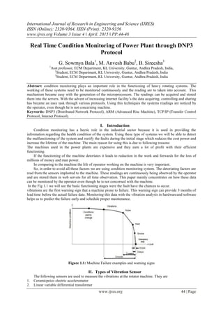
- 1. International Journal of Research in Engineering and Science (IJRES) ISSN (Online): 2320-9364, ISSN (Print): 2320-9356 www.ijres.org Volume 3 Issue 4 ǁ April. 2015 ǁ PP.44-48 www.ijres.org 44 | Page Real Time Condition Monitoring of Power Plant through DNP3 Protocol G. Sowmya Bala1 , M. Anvesh Babu2 , B. Sireesha3 1 Asst professor, ECM Department, KL University, Guntur, Andhra Pradesh, India, 2 Student, ECM Department, KL University, Guntur, Andhra Pradesh, India 3 Student, ECM Department, KL University, Guntur, Andhra Pradesh, India Abstract: condition monitoring plays an important role in the functioning of heavy rotating systems. The working of these systems need to be monitored continuously and the reading are to taken into account. This mechanism became easy with the generation of the microprocessors. The readings can be acquired and stored them into the servers. With the advent of increasing internet facility’s the data acquiring, controlling and sharing has became an easy task through various protocols. Using this techniques the systems readings are noticed by the operator, even though he is not concerning machine. Keywords: DNP3 (Distributed Network Protocol), ARM (Advanced Risc Machine), TCP/IP (Transfer Control Protocol, Internet Protocol). I. Introduction Condition monitoring has a hectic role in the industrial sector because it is used in providing the information regarding the health condition of the system. Using these type of systems we will be able to detect the malfunctioning of the system and rectify the faults during the initial stage which reduces the cost power and increase the lifetime of the machine. The main reason for using this is due to following reasons: The machines used in the power plants are expensive and they earn a lot of profit with their efficient functioning. If the functioning of the machine detoriates it leads to reduction in the work and forwards for the loss of millions of money and man power. In comparing to the machine the life of operator working on the machine is very important. So, in order to avoid all these factors we are using condition monitoring system. The detoriating factors are read from the sensors implanted to the machine. These readings are continuously being observed by the operator and are stored them in web servers for all time observation. This paper mainly concentrates on how these data can be monitored by the operator even though he is not concerned with the machine. In the Fig 1.1 we will see the basic functioning stages were the fault have the chances to occur. vibrations are the first warning sign that a machine prone to failure. This warning sign can provide 3 months of lead time before the actual failure date. Monitoring this data with the vibration analysis in hardwareand software helps us to predict the failure early and schedule proper maintenance. Figure 1.1: Machine Failure examples and warning signs II. Types of Vibration Sensor The following sensors are used to measure the vibrations at the rotator machine. They are 1. Ceramicpeizo electric accelerometer 2. Linear variable differential transformer
- 2. Real Time Condition Monitoring of Power Plant through DNP3 Protocol www.ijres.org 45 | Page 3. Proximity probes 4. Variable reluctance These sensors differ in the various factors like: 1. Damping co-efficient 2. Natural Frequency 3. cale factor Scale factor relates the output to an accelerometer and is linked to sensitivity together. The natural frequency and damping coefficient determines the accuracy level of the vibration sensor. For example if you were to pull the mass back away from equilibrium and release the mass. The mass vibrates forward and backward until it comes to rest. The Friction which is responsible in bringing the mass to rest is given by the Damping Co-efficient. III. Existing System In the modern power plants every rotating machine is monitored for their health condition through the vibration signals. At the bearing locations the vibration signals in trio directions namely vertical, horizontal, axial through the accelerators used and these analog signals are digitalized. Optimally a range of 5000 samples can be obtained ,andof those 4096 samples are used in applying the Fast Fourier transform mechanism so that we will be able to find the frequency components for each vibration signal. Using the results obtained it will be easy to determine the health condition efficiently. A continuous condition monitoring of the system identifies the fault were the remedy needs to be taken in time so ,as the machine to function more efficiently. Using intranet , the re quired information from the power plant stored in the expert server gets transmmited to the host web browser present at limited distance . For longer distances it is not recommended as the transmission is not efficient and accurate. IV. Proposed System These days we clearly see the advent of digital signal processing replace the era of analog. With the affect of these DSP many function status are being noticed by calculating their frequency’s. As the technology is being developed many more mechanisms can also be implanted to identify the Values. The main reason of the discussion is that the data obtained in the particular mechanism mentioned above can also be monitored staying at geographical locations. Various mechanisms are being proposed for the data acquisition mechanism and these mechanisms will not provide the secure transfer of data and can’t transfer for the long distances and is limited data size. In order to overcome all these issues we approached with the better communication protocol called DNP3(Distributed Network Protocol). Basically DNP3 is used between centrally located masters and the distributed systems. The master and remote uses the library having common objects to the information to exchange. It is designed in a reliable manner in providing the exchange media that will reduce the noise interface. 4.1 Understanding how DNP3 Elements communicate and Object Library Basic DNP3 have 27 Basic functions codes which help the remote and master to communicate by providing request response mechanism. This also provide the master to request and receive the status information from the remote and some function codes provide the master to configure the remote. Some function codes also provide the remote to respond the master Autonomously with the unsolicited message to their respective events during their installation. DNP3 also includes a library of objects that are used in data Acquisition and control systems. These objects include as binary inputs that are used to report the rotating system characteristicsi.e whether the system is power on or off and the access to panel s open or closed. These objects also provide some analog inputs that is used to report that is used to report the characteristics of range of values that the rotating machine is rotating with the rate of particular rpm an d how much power the rotataing system can take. With these library objects it is very much useful for the masters to integrate the data collected form the remote. Without these objects manufacturer has to prepare or develop his own model for acquiring the status and control of the remote. 4.2 DNP3 Message Structure Basically various protocols use Byte oriented mechanism with a single byte exchange to communicate and some protocols use the packet structure for the communication. This DNP3 work on packet oriented and the structure is below:
- 3. Real Time Condition Monitoring of Power Plant through DNP3 Protocol www.ijres.org 46 | Page Fig: DNP3 packet structure illustrated The Master sends a request for the object(s) and the remote’s response contain the requested information 4.3 DNP3 Layer Communication Here the working of the layers is clearly examined from the above diagram. The application layer is the combination of Application Service Data Unit(ASDU) and Application Protocol Control Info(APCI) block to make an Application Protocol Data Unit(APDU) Transport layerdivides the APDU into multiple segments having the size of 16 bytes and packs with 8-bit transport control header and 16-bit segment CRC separators with in transport frame. This Link Layer helps in adding the header which is control and the addressing information for the packet to delivery ti specific destination. These layers are packed into a 4 layered model .If the packet is sent through LAN/WAN these 3 DNP3 layers are packed up in to application layer. This assembled packet is again wrapped into the TCP through transport layer. This is inturn wrapped into the IP through internet layer. The 4th layer is network interface layer where the packet is transferred to the destination through the different media like twisted pair cable or co-axial cable. Fig :Architecture For Real Time Condition Monitoring of Power plants through DNP3 protocol
- 4. Real Time Condition Monitoring of Power Plant through DNP3 Protocol www.ijres.org 47 | Page Fig:DNP3 message passes through the protocol layers at both the manager and the agent. Each layer addresses a specific communication task V. Block Diagram for Proposed System Using this basic operation we will be able to find the functionality of system .Here the readings from the sensors are gathered and the these data are continuously stored into the servers. By using DNP3 protocol we will be able to find the readings during the vibration stage and the initial precautions will be taken to increase the life time of the system. In the fig specified the readings from the system are collected and the signals are digitalized to obtain the frequency of the particular eruption. These readings from the processor are transferred to the DNP web server through the communication port using fiber optic cables as the medium in the packets. VI. Features supported by DNP3 protocol Related to the paper on power plant condition monitoring DNP3 plays a more crucial in controlling the information basing on the rotating machine performance. This mechanism helps in providing the secure transfer of data and also supports the transfer of data to long distances with an advanced feature of supporting the transfer of 2K bytes of data at atime. This mechanism also supports various features like: Secure Authentication: In the power plant the authentication is completely required so, as the machine to be rotated at particular rpm is specified and the readings are to transferred without any unauthorised access to the servers. Authentication overcomes this issue, because the DNP3 post challenges the DNP3 master to ascertain if the command to control comes from a legitimate supply. The authentication key'supdated often between a DNP3 master and post. This communication is separate and not a part of commonplace DNP3 information transfer
- 5. Real Time Condition Monitoring of Power Plant through DNP3 Protocol www.ijres.org 48 | Page messages. If any post doesn't receive any updated key at intervals a nominative amount of time, or if the key's invalid, then the management commands from DNP3 Master, notwithstanding valid, won't be dead by the post device. The DNP3 protocol additionally uses an additional basic kind to make sure management commands square measure dead properly. This is called ―select-before-operate‖. During this case, a DNP3 Master can initial send a ―select‖ command, to that the outstation device can respond so, if the post device doesn't receive the ―operate‖ command within a nominative quantity of your time, it'll not execute the management action. Time Synchronisation: In the power plant when the machine function detoriates the signal needs to be given to the operator so, the efficient mechanism will be applied to overcome and improve the life time of the machine. At these particular stages of having chances to get faults the sensors have to be implanted to the machine so it will rise an alarm to the operator.The time synchronization plays an important factor in sending the correct sync pulse in right time in DNP3 protocol.A DNP3 outstation device can be configured to send a time sync request to the master or a DNP3 master can periodically send a time sync command to DNP3 outstation devices. Time sync is part of the DNP3 protocol specification. Key advantages of the time sync function include: Accurate and reliable time based information from the remote device is transferred to the DNP3 server. VII. Conclusion DNP3 protocol is an efficient protocol. It is used in higher systems like in power plants to minitor the rotating systems and to provide the health status of the machine for its efficient working and life span improvability. In these power plants various information regarding the machine are to be exchanged for observation. So, this protocol plays an efficient role in such kinds a larger devices. The DNP3 protocol with its features supporting best for the power plant condition monitoring system are as follows: Open protocol — allows the end-user to install equipment from different vendors while maintaining a single top end SCADA (or DNP3 master) • Allows the user to categorize field data, thus allowing for efficient communications and data transfer between a master and outstation. • Ability to log an event with a time and date stamp. • Secure authentication with dynamic key management between a DNP3 master and outstation. • Communication to multiple DNP3 Masters, thus making the same data available at multiple locations. VIII. Future Scope 1. Using this monitor conditioning system twe can provide the efficient transmission by replacing the ARM processor with the high speed device which supports for the best transmission. 2. This protocol can be implemented in such a way that the various data transfer rate can be modified depending on the type of data and its size so that the data sorage capacity can be improved. References [1] T Hema Madhuri, K. Sreenivasa Ravi –Real Time Conditioning of Power Plant Through Intranet-KL University, Guntur. [2] Supervisiory Control And Data Acquisition(SCADA) Systems by NATIONAL COMUNICATION SYSTEMS [3] Advantages of the DNP3 Communication Protocol in Water And Waste Water Telemetry Systems by Vishal Prakash [4] Jeon II Moon, Jung Sub Kim, Jong Bae Kim, Kye Young Lim, Byoung Wook Choi-R&D Center of LG Industrial Systems CO., Ltd, Anyangshi, South Korea b School of Electrical Engineering, Penn State University, USA Department of Control and Measurement Engineering, Sunmoon University, Kalsanri 100, Asanshi, Chungnam-do 336-840, South Korea [5] Scada Protocols And Communication Trends By Rao Kalapatapu Author Profile G. Sowmya Bala Asst professor at ELECTRONICS AND COMPUTER ENGINEERING Department, KL University. M.Anvesh Babu studying B.Tech (ELECTRONICS AND COMPUTER ENGINEERING) in KL University. B.Sireesha studying B.Tech (ELECTRONICS AND COMPUTER ENGINEERING) in KL University.