1. IS : 2911 ( Part III ) - 1980
Indian Standard
CODE OF PRACTICE FOR
DESIGN AND CONSTRUCTION OF PILE
FOUNDATIONS
PART Ill UNDER-REAMED PILES
(First Revision)
Fifth Reprint JULY 1998
UDC 624.1X33.04 : 006.76
Q Copyright 1981
BUREAU OF INDIAN STANDARDS
MANAK BHAVAN, 9 BAHADUR SHAH ZAFAR MARG
NEW DELHI 110002
Gr8 February 1981
2. IS:2911(PartIU)-1980
Indian Standard
CODE OF PRACTICE FOR
DESIGN AND CONSTRUCTION OF PILE
FOUNDATIONS
PART III UNDER-REAMED PILES
( First Revision)
Foundation Engineering Sectional Committee, BDC 43
Chairman
PROP DINESH MOHAN
Retresenting
Central Building Research
Roorkee
Institute (CSIR),
Members
DR’ R. K. BHANDARI Central Bltilding Research Institute (CSIR),
Koorkee
SHIU I. G. CHACKO
SHRI S. GUHA (Allen&e)
Calcutta Port Trust, Calcutta
SHRI K. N. DADINA In personal capacity (P 820, Block P, New A&ore,
SHRI M. G. DANDAVATE
Calcutta)
SHRI N. C. DUCCAL (Alternate)
Concrete Association of India, Bombay
SHR~ R. K. DAS GUPTA
SHFUH. GUHABISWA~ (Alternate)
Simplex Concrete Piles (I) Pvt Ltd, Calcutta
SHRI A. G. DA~TIDAR In personal capacity (5, Hungerford Court, 121
SHRI V. G. DESHPANDE
Hungerford Street, Calcutta)
DIRRCTOR (CSMRS)
Pressure Piling Co (India) Pvt Ltd, Bombay
Central Water Commission, New Delhi
DEPUTY DIRECTOR (CSMRS) (Alternate)
SHRI A. H. DIVANJX Asia Foundation and Construction Pvt Ltd,
SHRI A. N. JANGLE (Alternate)
Bombay
SHRI A. GH- Braitzlaz:urn & Jessop Construction-_Co Ltd,
SHRI N. E. A. RAGHAVAN (Al&mate)
DR GOPAL RANJAN
DR SHASHI K. GIJLHATI
University of Roorkee, Roorkee
lndian Institute of Technology, New Delhi
SHRI A. VARADARAJAN (@emate)
(Continued on page 2)
0 Copy@hr 1981
BUREAU OF INDIAN STANDARDS
This publication is protected under the Indian Copyright Acr (XIV of 1957) and
reproduction in whole or in part by any means except with written permission of the
publisher shall be deuned to be an inf .Wt of copyright under the said Act.
3. IS : 2911(Part III) - 1980
(Continued from page 1)
Members Represenfing
SHRI M. IYENGAR Engineers India Ltd, New Delhi
DR R. K. M. BwANDARI’(AltenZafe)
SHRI G. R. S. JA~N G. S. Jain & Associates, Roorkee
JOINT DIRECTOR RESEARCH (SM) Ministry of Railways
(RDSO)
JOINT DIRECTOR R&XARCH (B & S),
RDSO (Alfmute)
DR R. K. KAITI
SWRIK. K. KHANNA
’ SHRISUNIL BERRY (Alternate)
SHRI S. R. KULKARNI
SHRIS. ROY (Alternate)
SHRI 0. P. MALHOTRA
Indian Institute of Technology, Bombay
National Buildings Organizatton, New Delhi
M. N. Dastur and Company Pvt Ltd, Calcutta
Building and Roads Branch, Public Works Depart-
ment, Government of Punjab, Chandigarh
Central Warehousing Corporation, New Delhi
Mckenzies Limited,. Bombay
Bokaro Steel Plant (Steel Authority of India),
Bokaro Steel City
%RI A. P. &‘fPTHlJR
SHRI V. B. MATHUR
SHRIY. V. NARASIMHARAO
,Engineer-in-Chief’s Branch, Army HeadquartersBRIG O~IR SINGH
MAJ H. K. BHUTAN: (Alternure)
Sriru B. K. PANTHAKY Hindustan Construction Co Ltd, Bombay
SHRI V. M. MADOE (Alternate)
PRESIDENT Indian Gcotechnicj! Society, New Delhi. .
SECRETARY(Alternate)
PROFESSOR(CIVIL ENGG) College of Engineering, Guindy, Madras
A~~ISTAN? PROFESSOR (CIVIL
ENGG) (Alternate)
SHRI M. R. PUNJA Cementation Co Ltd, Bombay
SHRI A. A. RAJU Steel Authority of India, New Delhi
DR V. V. S. RAO Nag(adi Consultants Pvt Ltd, New Delhi
SHRI ARJUNRIJHSINCHANI Cement Corporation of India, New Delhi
SHRI 0. S. SRIVA~TAVA(Alternate)
SHRI K. R. SAXENA Engineering Research Laboratories, Government of
DR S. P. S~VA~TAVA
Andhra Pradesh, Hyderabad
United Technical Consultants Pvt Ltd, New Delhi
DR R. KAPUR (Alhnate)
SHRI N. SIVAGURU Roads Wing, Ministry of Shipping and Transport
SHRI S. SEETHARAMAN(Alternate)
SHRI T. N. SUBBA RAO Gammon India Ltd, Bombay
SHRI S. A. RzDDI (Alters&)
SUPERINTENDWGENGINEER(DESIGN) Central Public Works Department, New Delhi
Ezzmrrrvz ENGINEER(DESIGNV) (Alternate)
SHRI M. D. TAMBEKAR Bombay Port Trust, Bombay
SHRI D. AJITHA SIMHA, Director General, IS1 (l+@‘icio hfembn)
Director (Civ Engg)
Secretary
Snar K. M. MATHUR
Deputy Director (Civ Engg), IS1
(Continued ORpage 33)
2
4. .Is : 2911(PartIIq-1980
Indian Standard
-CODE OF PRACTICE FOR
DESIGN AND CONSTRUCTION OF PILE
FOUNDATIONS
PART III UNDER-REAMED PILES
( First Revision)
0. FOREWORD
0.1 This Indian Standard (Part III) (First Revision) was adopted by the
Indian Standards Institution on 26 May 19801 after the draft finalized by
the Foundation Engineering Sectional Comrmttee had been approved by
the Civil Engineering Division Council.
0.2 Under-reamed piles are of bored cast in situ and bored compaction
concrete types having one or more bulbs formed by suitably enlarging the
borehole for the pile stem. With the provision of bulb(s), substantial
bearing or anchorage is available. These piles find application in widely
varying situations in different types of soils where foundations are required
to be taken down to a certain depth in view of considerations like the need
(a) to avoid the undesirable effect of seasonal moisture changes as in
expansive soils; (b) to reach firm strata; (c) to obtain adequate capacity
for downward, upward and lateral loads and moments; or (d) to take the
foundations below scour level.
0.3 When the ground consists of expansive soil, for example black cotton
soil, the bulb of the under-reamed pile provides anchorage against uplift
due to swelling pressure -apart from the increased bearing. In case,of
filled-up or otherwise weak strata overlying. the firm strata, enlarged base
in tht! fo;m of under-reamed bulb in firm strata provides larger bearing
area and plies of greater bearing capacity can be made. In loose to medium
pervious sandy and silty strata, bored compaction piles can be used as the
process of compaction increases the load bearing capacity of the piles.
Under-reamed piles may also be used under situations where the vibration
and noise caused during construction of piles are ,to be avoided. The
provision of bulb(s) is of special advantage in under-reamed piles to resist
uplift and they can be used as anchors.
0.4 This standard was first published in 1973. This revision has been
undertaken to bring it in line with other Indian Standards on pile
foundation.
3
5. IS : 2911,(Part III) - 1980
0.5 The recommendations made in this code are based on the general
principles applicable to pile foundations and the experience of construction
of a large number of engineering works.
0.6 In the formulation of this standard due weightage has been given to
international co-ordination among the standards and practices prevailing
in different countries in addition to relating it to the practices in the field
in this$ountry. Considerable assistance has been given by Central Building
Research Institute, Roorkee, for preparing this standard.
0.7 For the purpose of deciding whether a particular requirement of this
standard is complied with, the Anal value, observed or calculated, expressing
the result of a testshall be rounded off in accordance with IS : 1960*. The
number of significant places retained in the rounded off value should be the
same as that of the specified value in this standard.
1. SCOPE
1.1 This standard (Part III) covers the design and construction of under-
reamed piles having one or more bulb(s) formed along the stem.
2. TERMINOLOGY
2.0 For the purpose of this standard, the following definitions shall apply.
2.1 Allowable Load - The load which may be applied to a pile after
taking into account its ultimate load capacity, pile spacing, overall bearing
capacity of the ground below the pile, the allowable settlement, negative
skin friction and the loading conditions including reversal of loads.
2.2 Batter Pile (Raker Pile) - The pile which is installed at an angle to
the vertical.
2.3 Bearing Pile - A pile formed in the ground for transmitting the load
of structure to the soil by the resistance developed at its tip or along its
surface or both. It may be formed either vertically or at an inclination
(Batter Pile) and may be required to take uplift. When it is primarily
meant for resisting uplift or pull it is called an ‘Anchor Pile’. If the pile
supports the’load primarily by resistance developed at the pile point or
base it is referred to as an ‘End Bearing Pile’ and if the load is supported
primarily by friction along its surface, the pile is termed as ‘Friction Pile’.
2.4 Bored Cast in situ Pile -A pile formed within the ground by
excavating or boring a hole within it, with or without the use of a temporary
casing and subsequently filling it with plain or reinforced concrete. When
the casing is left permanently it is termed as cased pile and when the casing
*Rules for rounding off numerical values (rtied).
4
6. IS : 2911 (Part III) 0 1980
is taken out it is termed as uncased pile. In installing a bored pile, the
sides of the bor’ehole (when it does not stand by itself) is required to be
stabilized with the aid of,a temporary casing, or with the aid of drilling
mud of suitable consistency.
2.5 Bored Compaction Pile - A bored cast in situ pile with or without
bulb(s) in which the compaction of surrounding ground and freshly filled
concrete in pile bore is simultaneously achieved by suitable method. If the
pile with bulb(s), it is known ‘under-reamed bored compaction pile’.
2.6 Cut-Off Level -It is the level where the installed pile is cut-off to
support the pile caps or beams or any other structural components at that
level. .
2.7 Datum Bar - A rigid bar placed on immovable supports.
2.8 Factor of Safety -
to the safe load of a pile.
The ratio of the ultimate load capacity of a pile
2.9 Initial Test_- It is carried out on test pile(s) generally made for the
purpose with a vrew to determining the safe load or ultimate load capacity
or both.
2.10 Kentledge - Dead weight used for applying a test load on pile.
2.11 Multi-Under-Reamed Pile - An under-reamed pile having more
than one bulb. The pile having two bulbs is known as double under-
reamed pile.
2.12 Net Displacement - Net movement of the pile top after the pile
has been subjected to a test load and subsequently released.
2.13 Routine (Check) Tests - It is carried out on a working pile with a
view to determining displacement corresponding to the allowable load.
2.14 Safe Load - It is a load on a pile derived by applying a factor of
safety on ultimate load capacity of pile or as determined by pile load test
or as obtained in accordance with 5.2.3.3.
2.15 Test Pile - A pile which is selected for load-testing and which is
subsequently loaded for that purpose. The test pile may form a working
pile itself if subject to routine load test with up to one and one-half times
the safe load in case of compression test and equal to safe load in uplift and
lateral thrust.
2.16 Total Displacement (Gross) - The total movement of the pile top
under a given load.
2.17 Total Elastic Displacement-This is the magnitude of the
5
7. IS : 2911 (Part III) - 1980
displacement of the pile due to rebound caused at the top after removal
of given test load. This comprises two components as follows:
a) Elastic displacement of the soil participating in load transfer; and
b) Elastic displacement of the pile shaft.
2.18 Trial Pile - One or more piles, which are not working pile, that may
be installed intially to assess load carrying capacity of the piles. These
are tested either to their ultimate bearing capacity or to twice the estimated
safe load.
2.19 Ultimate Load Capacity - The maximum load which a pile can
carry before failure of ground (when the soil fails by shear) or failure of pile
materials.
2.20 Under-Reamed Pile - A bored cast in situ or bored compaction
concrete pile with an enlarged bulb(s) made by either cutting or scooping
out the soil or by any other suitable process.
2.21 Working Load - The load assigned to a pile according to design.
2.22 Working Pile - A pile forming part of foundation of a structural
system.
3. NECESSARY INFORMATION
3.1 For the satisfactory design and construction of bored cast in situ and
bored compacted under-reamed piles and pile foundation, the information
on the following aspects is necessary:
4
b)
4
Site investigation data as- laid down in IS : 1892-1979* or any
other relevant Indian Standard. Sections of trial, borings, supple-
mented wherever appropriate by penetration tests, should incor-
porate data/information sufficiently on soil condition below the
anticipated level of pile tip.
The nature of the subsoil both around and beneath the proposed
pile should be indicated on the basis of appropriate tests of strength,
compressibility, etc. Ground-water levels and conditions (such as
artesian conditions) should be indicated. Results of chemical
tests to ascertain the sulphate and the chloride content and ground-
water should be indicated particularly in areas where large scale
piling is envisaged or where such information is not generally
available.
A qualitative indication of the degree of expansiveness of soil is
given in Appendix A. The free swell test will be carried out
according to IS: 2720 (Part-XL)-1977t.
In case of bridge foundations, data on high flood level, maximum
scouring depth, normal water level during working season, etc.
*Code of practice for subsurface investigations for foundations (jirst revision).
tMethod of test for soils, Part XL Determination of free swell index of soils.
6
8. 4
4
f1
&I)
4
33 As
IS: 2911(Part III) - 1980
In case of marine construction, necessary information as listed in
IS: 4651 (Part I)-1974* should be provided.
In case rock is encountered, adequate description of the rock to
convey its physical conditions as well as its strength characteristics
should be indicated.
In case of weathered rock, adequate physical description and its
expected physical behaviour on boring should be indicated.
‘General plan and cross section of the building showing type of
structural frame, including basement, if any, in relation to the
proposed pile cap top levels.
The general layout of the structure showing estimated loads,
vertical and horizontal, moments and torque at the top of pile
caps, but excluding the weight of the piles and caps. The top
levels of finished pile caps shall be clearly indicated.
It is preferable to have the dead load, equipment and live loads
separately indicated. Loads and moments for wind and earth-
quake should also be .separately indicated.
Sufficient information about structures existing nearby should be
provided.
far as possible, all information in 3.1 shall be made available to
the agency responsible for the design and/or construction of piles and/or
foundation work.
3.3 The design details .of pile foundation shall indicate the information
necessary for setting out the layout of each pile within a cap, cut-off levels,
finished cap levels, orientation of cap in the foundation plan and the safe
capacity of each type of piles, etc.
3.4 Due note shall be taken of the experience of under-reamed and other
piles in the area close to the proposed site and any soil strata report thereof.
4. MATERrALS
Cl cement -The cement used shall conform to the requirements of
:Sg;z%1976t, IS: 455-1976$, IS: 8041-1978$, IS : 6909-19731) or IS:1489-
‘*Codeof practice.for plauning and design of ports and ha&ours, P+rt I Site inv&igation
(j#Cf6&k).
fSpcc+a~on for ordinary and low heat Portkyd cement (Turk rcvirb) .
+Speuficat~on for Portland and a&q cement (f&d &.&VI).
~Specification for rapid hardening Portland cement.
K5+xification for supuaulphatcd cement.
QSpcciEcation for Portland pozzolana cement (scoondr&&n).
.
7
9. IS : 2911(Part III) - 1980
4.2 Steel - Reinforcement steel shall conform to IS : 432 (Part I)-1966*
or IS: 1139-1966t or IS : 1786-1979$ or IS : 226-19755. The stresses
allowed in steel should conform to IS : 456-197811.
4.2.1 For under-reamed bored compaction piles, the reinforcement cage
shall be prepared by welding the hoop bars to withstand.the stresses during
compaction process.
4.3 Concrete
4.3.1 Materials and methods of manufacture for cement concrete shall
in general be in accordance with the method of concreting under the
conditions of pile installation.
4.3.2 Consistency of concrete for cast in situ piles shall be suitable to the
method of installation of piles. Concrete shall be so designed or chosen
as to have homogeneous mix having a flowable ‘character consistent with
the method of concreting under the given conditions of pile installation.
In achieving these results, minor deviations in the mix proportions used in
structural concrete may be necessary.
4.3.3 Slump of concrete shall range between 100 mm to 150 mm for
concreting in water-free unlined boreholes. For concreting by tremie, a
slump of 150 mm to 200 mm shall be used.
4.3.4 1,n case of tremie concreting for piles of smaller diameter and
depth of up to 10 m, the minimum cement content should be 350 kg/m* of
concrete. For piles of large diameter and/or deeper piles, the minimum
cement content should be 400 kg/m* of concrete. For design purpose, the
strength of concrete mix may be taken equivalent to Ml5 and M20, res-
pectively, for concrete with cement content of 350 kg/m* and 400 kg/m*.
Where concrete of higher strength is needed, richer concrete mix with
higher cement content may be designed. In case of piles subsequently
exposed to free water or in case of piles where concreting is done under
water or drilling mud using methods other than the tremie, 10 percent extra
cement over that required for the design grade of concrete at the specified
slump shall be used subject to the minimum quantities -of cement specified
above.
4.3.5 For the concrete, water and aggregates specifications laid down
in IS: 456-197811 shall be followed in general. Natural rounded shingle
of appropriate size may also be used as coarse aggregate. Tt helps to give
high slump with less water cement ratio. For tremie concreting aggregates
having nominal size more than 20 mm should not be used.
*Specification for mild steel and medium tensile steel bars and hard drawn steel wire
for concrete reinforcement, Part I Mild steel + medjum tensile se bys (Iccondrev&m).
da
Specification for hot rolled mild steel, tm(AA)tensde :teel and hqh yield strength steel
ormed bars for concrete reinforcemen
$Specification for cold worked high strengthdeibrmed &xl bars for concrete reinf&ce-
ment (se& r&n).
@pecification for structural steel (standard quality) _fuc r&.&n).
Code of practice for plain and reinforced concrete y.( raGaIr).
8
10. IS : 2911 (Part III) - 1980
4.3.6 The concrete for piles in aggressive surroundings due to presence
of sulphates, etc, should have a concrete mix of appropriate type of cement
in suitable proportion.
4.3.6.1 If the concentration of sulphates (measured as SOs) exceeds
one percent in soil or 2 500 parts per million (ppm] in water a mix using
400 kg/m3 of sulphate resisting Portland cement should be used. For soils
with 0.5 to 1 percent of sulphates or ground water with 1 200 to 2 500 ppm,
the mix should have 330 kg/m3 of sulphate resisting Portland cement. For
concentrations lesser than above concrete mix with 330 kg/m3 ordinary
Portland cement or 310 kg/m3 sulphate resisting should be used. In place
of ordinary Portland cement, pozzolana cement/blast furnace slag cement
may be used.
4.3.6.2 Concentration of sulphates up to O-2 percent in soil and 300
ppm in water may be inconsequential.
4.3.7 For bored compaction piles rapid hardening cement (see 4.1) shall
not be used. To facilitate construction, admixtures for retarding the
setting of concrete may be used.
5. DESIGN CONSIDERATIONS
5.1 General - Under-reamed pile foundations shall be designed in
such a way that the load from the structure they support, can be transmitted
to the soil without causing any soil failure and without causing such settle-
ment, differential or total, under permanent transient loading as may
result in structural damage and/or functional distress, The pile shaft
should have ‘adequate structural capacity to withstand all loads (vertical,
axial or otherwise) and moments which are to be transmitted to the subsoil.
5.1.1 In deep deposits of expansive soils the minimum length of piles,
irrespective of any other considerations, shall be 3.5 m below ground level.
If the expansive,soil deposits are of shallow depth and overlying non-expan-
sive soil strata of good bearing or rock, piles of smaller length can also be
provided. In recently filled up grounds or other strata or poor bearing,
the piles should pass through them and rest in good bearing strata.
5.1.2 The diameter of under-reamed bulbs may vary from 2 to 3 times
stem diameter depending upon the feasibility of construction and design
requirements. In bored cast in Titusunder-reamed piles the bulb diameter
shall normally be 2.5 times, and in under-reamed compaction piles two
times.
’ 5.1.3 For piles up to 30 cm diameter, the spacing of bulbs should not
exceed 1.5 times the diameter of bulb. For piles of diameter greater than
30 cm spacing can be reduced to I.25 times the stem diameter.
5.1.4 The top-most bulb should be at a minimum depth of 2 times the
bulb diameter. In expansive soils it should also not be less than l-75 m
below ground level. The minimum clearance below the underside of pile
9
11. IS : 2911 (Part III) - 1980
cap embedded in the ground and the bulb should be a minimum 1.5 times
the bulb diameter.
5.1.5 Under-reamed piles with more than two bulbs are not advisable
without ensuring their feasibility in strata needing stabilization of boreholes
by drilling mud. The number of bulbs in case of bored compaction piles
should not exceed two in such strata.
5.1.6 The minimum diameter of stem for borehole needing stabilization
by drilling mud should be 25 cm.
5.1.7 The minimum diameter of stem for strata consisting of harmful
constituents, such as sulphates, should be 30 cm.
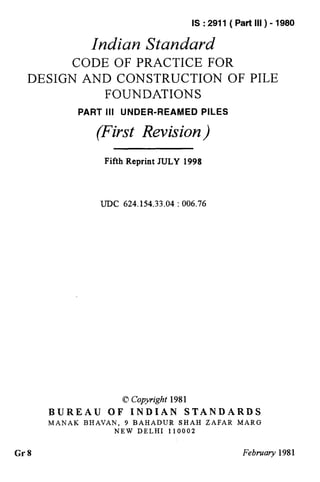
5.1.8 For guidance typical details of bored cast in silu under-reamed pile
foundations are shown in Fig. 1.
5.1.9 For batter piles, a batter of 30” for piles in dry ground conditions
and 15” with horizontal for water or drilling mud filled holes should generally
not be exceeded. The under-reamed compaction piles are normally
constructed up to a batter of 15”.
5.2 Design of Piles - The load carrying capacity of under-reamed pile
depends mainly on the pile dimensions and soii strata. Axial load on a
pile is transmitted by point bearing at the toe and the projected area of
the bulb(s) and skin friction along the pile stem. Depending upon the
nature of soil and pile geometry, in addition to the skin friction on stem,
friction can develop on the soil cylinder between the extreme bulbs. In
under-reamed compaction piles, the mechanism of load transfer remains the
same but soil properties improved by compaction process are considered.
In uplift load, point bearing component at toe is absent but unlike other
straight shaft piles, point bearing on an anular projection of the bulb is
present. Lateral load and moment are sustained by horizontal soil reaction
developed along the pile length, which depends on several factors.
The design of piles shall be such that it has an adequate factor of safety:
a) as a structural member to transmit the imposed loads, and
b) against failure of strata due to reaching ultimate strength. Further
it should ensure that the desired limit of settlement is not exceeded.
5.2.1 Pile as a Struc@al Member - The pile should have adequate strength
to sustain the design loads. The pile cross-section should be checked for
combined effect of vertical loads (compressive and uplift) and/or lateral
loads and moments. The stem should be designed as a short column
considerating both concrete and steel (see 5.2.2) by the limit state method
or working stress method. In case of latter, the permissible increase in
stresses shall be taken for wind and seismic loads. (see IS : 875-1964* and
IS : 1893-1975t.)
*Code of practice for structural safety of buildings: Loading standards (rev&j).
tcriteria for earthquake resistant design of structures (third revision).
10
12. IS : 2911(Part III) - 1980
BORING LEV<L
FOR MAKING
SECOND/LAST
BULB
7 :
t
--Id--
COVER 75 TO 100
9,=45” Approx,& 30°-45”Approx,Du=NonnallyZ?5D
1A %kTION OF ~%NOLE 1B !hCTION OFMULTI-
UNDER-REAMEDPILE UNDER-REAMEDPx~x
All dimensionsin millimctres
Fm. 1 TYPICALDETAILSOFBOREDCASTin situ UNDER-REAMED
PILE FOUNDATIONS
5.2.2 Reinfwcemmt in Piles - The provision of reinforcement will depend
on nature and magnitude of loads, nature of strata and method of installa-
tion. It should be adequate for vertical load, lateral load and moments,
acting individually or in combination. It may be curtailed at appropriate
depth subject to provision given in 5.2.2.1 and 5.2.2.2.
5.2.2.1 The minimum area of longitudinal reinforcement in stem
should be 0.4 percent of mild steel (or equivalent deformed steel). Rein-
11
13. IS : 2911(Part lII) - 1980
forcement is to be provided in the full length irrespective of any other
considerations and is further subject to the condition that a minimum
number of three lo-mm diameter mild steel or three 8*mm diameter high
strength steel bars shall be provided. The transverse reinforcement as
circular stirrups shall not be less than 6-mm diameter mild steel bars at a
spacing of not more than the stem diameter or 30 cm whichever is less.
In under-reamed compaction piles, a minimum number of four, 12-mm
diameter mild steel or four IO-mm diameter high strength steel bars shall
be provided. For piles of lengths exceeding 5 m and or 37.5 cm diameter,
a minimum number of six 12-mm diameter bars of mild or high strength
steel shall be provided. For piles exceeding 40 cm dia, a minimum number
of six 12-mm diameter mild or high strength steel bars shall be provided.
The circular stirrups for piles of lengths exceeding 5 m and diameter exceed-
ing 37.5 cm shall be of 8 mm diameter bars.
5.2.2.2 For piles subjected to uplift loads, adequate reinforcement shall
be provided to take full uplift which shall not be curtailed at any stage.
5.2.2.3 For piles up to 30 cm diameter, if concreting is done by tremie,
equivalent amount of steel placed centrally may be provided.
5.2.2.4 The minimum clear cover over the longitudinal reinforcement
shall be 40 mm. In aggressive environment of sulphates, etc, it may be
increased to 75 mm.
5.2.3 Safe Load - Safe load on a pile can be determined from (a) calculat-
ing tiltimate load from soil properties and applying suitable factor of safety,
(b) load test on pile as provided in IS : 2911 (Part IV)-1979*, and (c) safe
load tables.
5.2.3.1 Safe loadfrom ultimate load capacity - The ultimate load capacity
of a pile can be calculated from soil properties. The soil properties required
are strength parameters, cohesion, angle of internal friction and soil density.
If these properties are not available directly from laboratory and field tests,
they may be indirectly obtained from in situ penetration test data [IS : 4968
(Part II)-19767 and IS : 6403-1971$]. The success of the approach essenti-
ally depends how realistically the soil properties are determined or deduced.
a) Clayey soils
For clayey soils the ultimate load carrying capacity of an under-reamed
pile may be worked out from tpe following expressions:
QU= A,.JV,C,+A,.JV,.C’,+C,‘.A,’ + .c.C,.A,
where
Qu (kg) = ultimate bearing capacity of pile;
~4, (cm”) = cross-sectional area of pile stem at toe level;
*Code of practice for design and construction of pile foundations: Part IV Load test on
piles.
tMethod for subsurface sounding’for soils: Part III Static cone penetration test (_/irst
rtiion) .
$Code of practice for determination of allowable bearing pressure on shallow foundations.
12
14. IS : 2911(Part III) - 1980
Jve
C, (kgf/cmt) z
A, (cm2) =
C’, (kgf/cm2) =
;a (kgf/cm2) z
A, (cm2) =
A’, (cm2) =
bearing capacity factor, usually taken as 9;
cohesion of the soil around toe;
7r/4 (D2U-D2) where D,(cm) and D (cm) are the
under-reamed and stem diameter, respectively;
average cohesion of soil around the under-reamed
bulbs;
reduction factor (usually taken 0.5 for clays) ;
average cohesion of the soil along the pile stem;
surface area of the stem; and
surface area of the cylinder circumscribing the under-
reamed bulbs.
The above expression holds for the usual spacing of under-reamed bulbs
spaced at not more than one-and-a-half times their diameter.
NOTE 1 - The first two terms in formula are for bearing and the last two for friction
components.
NOTE 2 - If the pile is with one bulb only the third term will not occur.
NOTE 3 - For calculating uplift load first term will not occur in formula.
b) Sandy soils
For sandy soils the following expression be used:
r=n
Qu= A,.(&.D.X..NX+ X.dJV,,)+A, (~.D,.n.h..hQ+h.Nq x d,.
where
A, (cm2) =
A, (cma) =
?=
; (kglcms) =
.NAand IV, =
dr (cm) =
d+ (cm) =
K =
S =
dl (cm) =
d,, (cm) =
r=l
+-&.n.D.X.K tan S x (d:+df--di)
rr/4.D2, where D (cm) is stem diameter;
n/4(Dz-Da) where D, (cm) is the under-reamed
bulb diameter;
number of under-reamed bulbs;
average unit weight of soil (submerged unit weight in
strata below water table);
bearing capacity factors depending upon the angle
of internal friction;
depth of the centre of different under-reamed bulbs
below ground level ;
total depth of pile below ground level;
earth pressure coefficient (usually taken 1.75 for sandy
soils) ;
angle of wall friction (may be taken equal to the angle
of internal friction 4) ;
depth of the centre of first under-reamed bulb; and
depth of the centre of the last under-reamed bulb.
NOTE I- ‘?Yhefirst two terms in the formula are for bearing component and the
‘as;= $W fnction cpmpone$. .<.
- For uphft bearing on tip, Ap will not occur.
13
15. IS :2911 (Part RI) - 1980
NOTE 3 - NAwill be as specified in 1S : 6403-1971* and Jv, will be taken from Fi .2.
This factor, apart from the angle of internal friction 4 depends upon the meth o! of
installation of pile and the component containing this factor will generally be over
estimated (up to about twice) in bored piles.
c) Soil strutu having both cohesionandfriction
In soil strata having both cohesion and friction or in layered strata having
two types of soil, the beari.ng capacity may be estimated using both the
formula. However, in such cases the load tests will be a better guide.
d) Comjactionpiles in sandy strata
For bored compaction piles in sandy strata, the formula in 5.2.3.1(b)
shall be applicable but the modified value of C$will be used as given below:
where
$= angle of internal friction of virgin soil.
The values of NA, .N, and 6 are taken corresponding to
The value of the earth pressure coefficient K will be 3.
4l
e) Piles resting on rock
For piles resting on rock, the bearing component will be
multiplying the safe bearing capacity of rock with bearing
stem plus the bearing provided by the bulb portion.
obtained by
area of pile
f) Factors of safety
To obtain safe load in compression and uplift from ultimate load capacity
generally the factors of safety will be 2.5 and 3, respectively. But in case
of bored compaction piles with bulb diameter twice the shaft diameter, the
factor of.safety in compression should be taken 2.25.
553.2 Safe 1oadJiom pile load tests- The safe load on pile(s) in com-
pression uplift and lateral can be determined by carrying out load test
on piles in accordance with IS : 2911 (Part IV)-1979t. In sizable work
(more than two hundred piles) where detailed information about the strata
and the guidance of past experience is not available, there should be a
minimum of two pile load tests before finalizing the safe load on piles.
NOTE- It is unlikely that two simihu pile load testa ‘ve the same loaddetlection
W viour. Also, ground conditions, position of water taT le, moisture content in soil
and desiccation of top strata, can affect the load tests conducted at different tima of
the ye. These factors should be kept in view while deciding the safe load.
5.2.3.3 In the absence of actual tests and detailed investigations, the
safe load on under-reamed piles of bulb diameter 2-5 times the stem
diameter may be taken as given in Appendix B.
*Code of praeticcfor determination of allowable bearing presure on &allow foundations.
t&de of practice for dcaign and construction of pile foundations: Part IV Load test on
pile%
14
16. Is : 2911(Part III) - 1980
20 25 30 35 *u IDJ
ANGLE OF INTERNAL FRlCTlON fi
FIG.2 BEARING CAPACITY FACTOR Na
15
17. IS : 2911(Part III) - 1980
5.2.3.4 The lesser of the two safe loads obtained from 5.2.3.1
and 5.2.3.3 should be used in designs. Higher values can be used if
established by initial load tests.
5.2.3.5 Permissible increase over safe load on biles
4
b)
Overloading- When a pile designed for a certain safe load is found
to fall just short of the required load carried by it, an overload of
up to 10 percent of the safe load on pile may be allowed on each
pile. The total overloading on group should not be more than 10
percent of the safe load on group, nor more than 40 percent of the
safe load on single pile.
Tramient loading- The maximum permissible increase over the safe
load of a pile as arising out of wind loading is 25 percent. In case
of loads and moments arising out of earthquake effects the increase
over the safe load on a pile may be limited to the provisions contained
in IS : 1893-1975*. For seismic loads, under-reamed piles shall be
treated as point bearing piles. The seismic and wind forces will
not be considered to act simultaneously. For transient loading arising
out of superimposed loads, no increase generally may be allowed.
For broken wire conditions in transmission line tower foundations,
permissible increase will be as provided in IS : 4091-19797.
NOTE- If any increasein load on a pile has already been permitted for reasons
other than 5.!235, the total increase over safe load including those of 593.5 shall not
exceed 50 percent.
5.2.4 Jvegative Skin Friction or Drag Down Force-When a soil stratum
through which a pile shaft has penetrated into an underlying hard stratum,
compresses as a result of either it being unconsolidated or it being under
a newly placed fill or as a result of remoulding during driving of the pile,
a drag-down force is generated into the pile shaft up to a point in depth
where the surrounding soil does not move downward relative to the pile
shaft.
NOTE -Estimation of this drag-down force is still under investigation, although a
few empirical approaches are in use. The concept is constantly. under revision and,
therefore, no definite proposal is embodied in this standard. (Recognition of the existence
of such a phenomenon shall be made and suitable reduction shall be made to the allow-
able load where appropriate. There is no evidence to show that the use of drilling
fluids for the construction of piles afkcts the skin friction.)
5.2.5 LatGral Load on P&s - A pile may be subjected to transverse force
from a number of causes, such as wind, earthquake, water current, earth
pressures, effect of moving vehicles or ships, plant and equipment, etc. The
lateral load carrying capacity of a single pile depends not only on the
horizontal subgrade modulus of the surrounding soil but also on the structural
strength of the pile shaft against bending consequent upon application of a
lateral load. While &msidering lateral load on piles, effect of other
*Criteria for eartlqttake resistant design of atructurca (tied rmision).
tCode of practice for design and construction of foundations for transmission line towers
urd poles (jrfi r&).
16
18. I!3 : 2911(Part III) - 1980
existent loads including the axial load on the pile should be taken into
consideration for checking the structural capacity of the shaft.
Piles under the action of lateral load and moment can be analysed by
the modulus of subgrade reaction approaches. Due to the presence of
bulbs, under-reamed piles tend to behave more as rigid piles and the analysis
can be done on rigid pole basis. Normally reinforced long single bulb
piles which are not rigid may be analysed after the generalized solutions
of Matlock and Reese for sandy soils and Broms for clayey soils. For lateral
loads with or without axial loads, up to those given in the Table 1 of
Appendix B, no analysis may be necessary, if external moment is not acting.
In the absence of actual in situ test values from prototype pile load test,
the modulus of subgrade reaction values may be taken from the Table 2
given in Appendix C.
NOTE- It may be kept in view that modulus of subgrade reaction is a criti$Lf;o;er
in the above analysis, yet there is no precise method for determining it.
it will be realistic to ascertain the adequacy of design by field tests.
2
5.2.6 Batter Piles (Raker Piles) - Raker piles are normally provided
where vertical piles cannot resist the required applied horizontal forces.
In the preliminary design the load on raker ~pileis generally considered to
be axial. The distribution of load between raker and vertical piles in
a group may be determined by graphical or analytical methods. Where
necessary, due consideration should be given to secondary bending induced
as a result of the pile cap movement, particularly when the cap is rigid.
Free standing raker piles are subjected to -bending moments due to their
own weight or external forces from other causes. Raker piles embedded
in 8l.l or consolidating deposits may become laterally loaded owing to the
settlement of the surrounding soil.
55.7 Sfiacing of Piles
55.7.1 Spacing of piles shall be considered in relation to the nature
ofground, the types of piles and the manner in which the piles transfer the
load to the ground.
52.7.2 Generally the centre to centre spacing for bored cast in situ
under-reamed piles in a group should be two times the bulb diameter (20,).
It shall not be less than l-5 D,,. For under-grade beams the maximum
spacing of piles should generally not exceed 3 m. In under-reamed com-
paction piles, generally the spacing should not be less than l-5 D,, If the.
adjacent piles are of different diameter, an average value of bulb diameter
should be taken for spacing.
5.2.8 Grouping and Layout
528.1 For bored case in situ under-reamed piles at usual spacing
of 2 D,, the group capacity will be equal to the safe load of individual
pile multiplied by the number of piles in the group. For piles at a spacing
of l-5 D, the,safe load assigned per pile in a group should be reduced by
10 percent.
17
19. IS : 2911 (Part III) - 1980
In under-reamed compaction piles, at the usual spacing of 1.5 D.,, the
group capacity will be equal to the safe load on individual pile multiplied
by the number of piles in the group.
Nom - In under-reamed compaction piles, the capacity of the group may be more
than given in 5.2.&l on account of the compaction effect.
5.2.8.2 In non-expansive soils, when the cap of the pile group is cast
directly on reasonably firm stratum it may additionally contribute towards
the bearing capacity of the group.
5.2.8.3 The settlement of pile groups depends upon soil and pile
characteristics, spacing, group size method of installation and magnitude .
and nature of loading. In clays sometimes long term settlements can
become important while in sands almost all the settlements will be over
quickly.
A group of free standing piles is likely to settle more than a single pile
but this increase may be marginal if the safe load on the piles is according
to 5.2.3 and 5.2.8.1.
NOTE 1 - The settlement, in case of piles in sand, are generally computed from
empirical relations. A suggested relationship for estimating settlements of free standing
under-reamed pile groups in sands is:
where
Ss = settlement of group in cm,
St = settlement of single pile in cm; piles are under the same safe load per pile,
B = distance between outer piles centre in cm, and
D = pile stem diameter in cm.
In clays the immediate settlements are computed using theory of elasticity and the
long term settlements by consolidation theory. For the later, the pile group is consi-
dered as a footing at the centres of the lowermost bulbs.
It may be noted that computed settlements, by the above approaches particularly for
piles in clay, are very large as compared to actually occurring in practice.
Nom 2 -For the groups with caps resting on ground settlements are comparable
with an isolated pile.
NOTE 3 - In the case of under-reamed compaction piles with cap resting on ground,
which is very often the case, the settlements of groups may be even less than the settlement
of an isolated pile.
5.2.8.4 In case of structure supported on single pile/group of piles,
resulting into large variation in the number of piles from column to column
it is likely that a high order of differential settlement may result depend-
ing on the type of subsoil supporting the piles. Such high order of
differential settlement may be either catered for in the structural design
or it may be suitably reduced by judicious choice of variations in the actual
pile loadings. For example, a single pile cap may be loaded to a level
higher than that of a pile in a group in order to achieve reduced differential
settlement between two adjacent pile caps supported on differential number
of piles.
18
20. IS : 2911 (Part III) - 1980
5.2.8.5 In load bearing walls, piles should generally be provided
under all wall junctions to avoid point loads on beams. Positions of inter-
mediate piles are then decided by keeping door openings fall in between
two piles as far as possible.
5.3 Grade Beams
5.3.1 The grade beams supporting the walls shall be designed taking
due account of arching effect due to masonry above beam. The beam with
masonry due to composite action behaves as a deep beam.
For the design of beams, a maximum bending moment of ~1~150, where
w is uniformly distributed load per metre run (worked out by considering
a maximum height of two storeys in structures with load bearing walls
and one storey in framed structures) and 1 is the effective span in metres,
will be taken if the beams are supported during construction till the masonry
above it gains strength. The value of bending moment shall be increased
to w12/30 if the beams are not supported. For considering composite
action the minimum height of wall shall be 0.6 times the beam span. The
brick strength should not be less than 30 kgf/cm2. For concentrated loads
and other loads which come directly over the beam, full bending moment
should be considered.
5.3.2 The minimum overall depth of grade beams shall be 150 mm.
The reinforcement at bottom should be kept continuous in all the beams
and an equal amount may be provided at top to a distance of quarter span
both ways from the pile centres.
The longitudinal reinforcement both at bottom and top should not be
less than three bars of 10 mm diameter mild steel (or equivalent deformed
steel).
Stirrups of 6-mm diameter bars should be at a 300 mm spacing which
should be reduced to 100 mm at the door openings near the wall edge up
to a distance, of three times the depth of beam. No shear connectors are
necessary in wall.
5.3.3 In expansive soil, the grade beams shall be kept a minimum of
80 mm clear off the ground. In other soils, the beams may rest on ground
over a levelling concrete course of about 80 mm (see Fig. 3). In this case,
part load may be considered to be borne by the ground and it may be
accounted for in the design of piles. However, the beams should be designed
as per clause 5.3.1.
5.3.4 In case of exterior beams over piles in expansive soils, a ledge
projection of 75 mm thickness and extending 80 mm into ground (seeFig. 3)
shall be provided on outer side of beam.
5.4 Design of Pile Cap -Pile caps are generally designed considering
pile reaction as either concentrated loads or distributed loads. The depth
of pile cap should be adequate for the shear for diagonal tension and it
should also provide for necessary anchorage of reinforcement both for the
column and the piles.
19
21.
22. IS : 2911(Part III) - 1980
5.4.1 The pile caps may be designed by assuming that the load from co-
lumn or pedestal is dispersed at 45” from the top of the cap up to the mid-
depth of the pile cap from the base of the column or pedestal. The reaction
from piles may also be taken to be distributed at 45” from the edge of the
pile, up to the mid-depth of the pile cap. On this basis, the maximum
bending moment and shear forces should be worked out at critical sections.
5.4.2 When pile reactions are considered as point loads, the critical
section for shear in diagonal tension is taken at a distance equal to half
the depth of cap from the face of the column or pedestal. For bending
moment and shear for bond, the critical section is taken at the face of the
column or pedestal. In computing the external shear or the critical section
the entire reaction of any pile of diameter D whose centre is located at D/2
or more outside the section shall be assumed as producing shear on the
section; the reaction from any pile whose centre is located at D/2 or more
inside the section shall be assumed as producing no shear on the section.
For intermediate positions of the pile centre, the portion of the pile
reaction to be assumed as producing shear on the section shall be based on
straight line interpolation between full value at D/2 outside the section and
zero value inside the section.
5.4.3 The cap may also be designed as a solid slab carrying concentrated
loads from piles. A square/rectangular pile cap can be divided in four
triangular/trapezoidal areas by drawing diagonal lines at 45” from the
corners. When the pile is cut by the line, the load on this pile is shared
equally between the adjacent areas. The reaction of piles under an area
will be taken towards producing shear. The bending moment are assumed
to act from the centre of piles under an area at the face of the nearest
pedestal or column.
5.4.4 Full dimension of the cap shall be taken as width to analyse the
section for bending and shear in respective direction. Method of analysis
and allowable stresses may be according to.%: 456-1978*.
5.4.5 The clear overhang of the pile cap beyond the outer most pile in
the group shall normally be 100 to 150 mm, depending upon the pile size.
5.4.6 The cap is generally cast over a 75 mm thick levelling course of
concrete. The clear cover for main reinforcement in the cap slab shall be
not less than 75 mm.
5.4.7 The pile should pro_jcct 40 mm into the cap concrete.
6. EQUrPMENT AND ACCESSORIES
6.1 The selection of equipment and accessories will depend upon the type
of under-reamed piles, site conditions and nature of strata. Also it will
depend on economic considerations and availability of manually or pover
operated equipment.
*Code of practice for plain and reinforced concrete (f&d rc&&n).
21
23. IS : 2911(Part III) - 1980
6.2 A typical list of equipment for manual construction is given in
Appendix D.
6.3 Bore holes may be made by earth augers. In case of manual boring,
an auger boring guide shall be used to keep the bores vertical or to the
desired inclination and in position.
After the bore is made to the required depth, enlarging of the base shall
be carried out by means of an under-reaming tool.
6.4 In ground with high water table having unstable pile bores, boring and
under-reaming may be carried out using a suitable drilling mud. General
guidelines for bentonite drilling mud are given in Appendix E. In normally
met soil strata, drilling mud can be poured from top while boring and under-
reaming can be done by normal spiral earth auger and under-reamer.
The level of drilling mud should always be about one metre above water
table or the level at which caving in occurs. In case of very unstable strata
with excessive caving in, continuous circulation of drilling mud using suitable
pumping equipment and tripod, etc, alongwith modified auger and under-
reamer may be used.
6.5 Sometimes permeable strata overlying a rim clayey stratum may be
cased and normal boring and under-reaming operation may be carried out
in clayey stratum.
6.6 To avoid irregular shape and widening of bore hole in very loose strata
at top, a casing pipe of suitable length may be used temporarily during
boring and concreting.
6.7 For improved control over the inclination of batter piles, a tripod hoist
with fixed pully should be used for lowering in of under-reaming tools.
6.8 For placing the concrete in bore holes full of drilling mud or subsoil
water, tremie pipe of not less than 150 mm diameter with flap valve at the
bottom should be used.
6.9 For batter under-reamed piles, the reinforcement cage should be placed
guiding it by a chute or any other suitable method. If concreting is not
done by tremie, it should be done by chute.
6.10 In under-reamed compaction piles, suitable devices should be used for
guiding the movement of drop weight and specified core assembly for its
vertical driving. For operating the drop weights of adequate capacity,
suitable winch with hoisting attachment should be used.
7. CONSTRUCTION
7.1 Under-reamed piles may be constructed by selecting suitable installation
techniques at a given site depending on subsoil strata conditions and type
of under-reamed pile and number of bulbs.
22
24. IS : 2911 (Part III) - 1980
7.2 In construction with the equipment given in 6, initially boring guide
is fixed with its lower frame levelled for making desired angular adjustment
for piles at batter. Boring is done up to required depth and under-reaming
is completed.
7.2.1 In order to achieve proper under-reamed bulb, the depth of bore
hole should be checked before starting under-reaming. It should also be
checked during under-reaming and any extra soil at the bottom of bore hole
removed by auger before reinserting the under-reaming tool.
7.2.2 The completion of desired under-reamed bulb is ascertained by
(a> the vertical movement of the handle, and (6) when no further soil is
cut.
7.2.3 In double or multi-under-reamed piles, boring is first completed
to the depth required for the first (top) under-ream only and after complet-
ing the under-reaming, boring is extended further for the second under-
ream and the process is repeated.
7.3 Control of Alignment - The piles shall be installed as correctly as
possible at the correct location and truly vertical (or at the specified batter).
Great care shall be exercised in respect of single pile or piles in two-pile
groups under a column. As a guide, for vertical piles a deviation of 1.5
percent and for raker piles a deviation of 4 percent shall not normally
be exceeded. In special cases, a closer tolerance may be necessary. Piles
shall not deviate more than 75 mm or one quarter the stem diameter,
whichever is less (75 mm or D/ 10 whichever is more in case of piles having
diameter more than 600 mm) from the designed position at the working
level. In the case of single pile under a column, the positional deviation
should not be more than 50 mm or one quarter of the stem diameter which-
ever is less (100 mm in case of piles having diameter more than 600 mm).
For piles where cut-off is at substantial depths, the design should provide
for the worst combination of the above tolerances in position and inclination.
In case of piles deviating beyond these limits, corrective measures where
necessary may be taken in the form of increasing pile size, provision of
extra reinforcement in the pile, redesign of pile cap and pile ties. If the
resulting eccentricity cannot be taken care of by the above measures, the
piles should be replaced or supplemented by one or more additional piles.
NOTE- In case of raker piles up to a rake of 1in 6, there may be no reduction in the
capacity of the pile unless othenvise stated.
7.4 Concreting shall be done as soon as possible after completing the pile
bore. The bore hole full of drilling mud should not be left unconcreted
for more than 12 to 24 hours depending upon the stability of bore hole.
7.5 For placing concrete in pile bores, a funnel should be used and method
of concreting should be such that the entire volume of the pile bore is filled
23
25. IS : 2911(Part III) - 1980
up without the formations of voids and/or mixing of soil and drilling fluid
in the concrete.
7.5.1 In empty bore holes for under-reamed piles a small quantity of
concrete is poured to give about a 100 mm layer of concrete at the bottom.
Reinforcement is lowered next and positioned correctly. Then concrete
is poured to fill up the bore hole. Care should be taken that soil is not
scrapped from sides if rodding is done for compaction. Vibrators shall
not be used.
7.5.2 If the water is confined up to the bucket length portion at the
toe and seepage is low, the water should be bailed out and concreting
should be done as in 7.5.1.
7.5.3 In case the pile bore is stabilized with drilling mud or by maintaining
water head within the bore hole, the bottom of bore hole shall be carefully
cleaned by flushing it with fresh drilling mud, and pile bore will be checked
for its depth immediately before concreting.
Concreting shall be done by tremie method. The tremie should have a
valve at its bottom and lowered with its valve closed at the start and filled
up with concrete. The valve is then qpened to permit the flow of concrete
which permits the upwards displacement of drilling mud. The pouring
should be continuous and tremie is gradually lifted up such that the tremie
pipe opening remains always in the concrete. If the final stage the quantity
of concrete in tremie should be enough so that on tinal withdrawal some
concrete spills over the ground.
NOTZ 1 - The concrete should be coherent, rich in cement (not less than 350 l&/m%)
and of slump not less than 150 mm.
NOTE 2- The tremie pipe should always penetrate well into the concrete with an
adequate margin of safety against accidental withdrawal of the pipe is surged to discharge
the concrete
NOTE 3 - The pile should be concreted wholly by tremie and the method ofdeposition
should not be changed part way up the pile, to prevent the laitance from being entrapped
within the pile.
NOTE 4 - All tremie tubes should be scrupulously cleanrd before and after use.
NOTE 5 - Normally concreting of the piles should be uninterrupted. In the excep-
tional case of interruption of concreting, but which can be resumed within 1 or 2 hours,
the tremie shall not be taken out of the concrete. Instead it shall be raised and lowered
slowly, from time to time to prevent the concrete around the tremie from setting. Con-
creting should be resumed by introducing a little richer concrete with a slump of about
200 mm for easy displacement of the partly set concrete. If the concreting cannot
be resumed before final set-up of concrete already placed, the pile so cast may be rcjectcd,
or used with modifications.
Nom 6 - Tn case of withdrawal of tremie out of the concrete, either a&dentally
or to remove a choke in the tremie, the tremie may be re-introduced in a manner to
prevent impregnation oflaitance or scum lying on the topof theconcrete already deposited
in the bore.
24
26. Is : 2911(Part III) - 1980
7.5.4 In inclined piles, the concreting should be done through achute
or by tremie method.
7.5.5 For under-reamed bore compaction piles, the pile bore is first filled
up without placing any reinforcement. Concreting is done as in 7.5.1
depending upon situation. Soon after, the specified core assembly shall
be driven and extra concrete shall be poured in simultaneously to keep the
level of concrete up to ground level. If hollow driving pipe is used in core
assembly, the pipe-shall be withdrawn after filling it with fresh concrete
which will be left behind.
NOTE- In under-reamed bored compaction piles, concreting should be uninterrupted
and notes 45) and (6) under clause 7.5.3 will not apply.
7.5.6 The top of concrete in a pile shall be brought above the cut-off
level to permit removal of all laitance and weak concrete before capping
and to ensure good concrete at the cut-off level for proper embedment into
the pile cap.
7.5.7 Where cut-off level is less than 1.5 metre below working level,
concrete shall be cast to a minimum of 300 mm above cut-off level. For
each additional O-3 m increase in cut off level below working level, addi-
tional coverage of 50 mm minimum shall be allowed. Higher allowance
may be necessary depending on the length of the pile. When concrete is
placed by tremie method, it shall be cast to the piling platform level to
permit overflow of concrete for visual inspection or to a minimum of one
metre above cut-off level. In the circumstance where cut-off level is below
. ground water, the need to maintain a pressure on the unset concrete equal
to or greater than water pressure should be observed and accordingly
length of extra concrete above cut-off level shall be determined.
7.5.8 Defective Pile -In case, defective piles are formed, they shall be
removed or left in place whichever is convenient without affecting per-
formance of the adjacent piles or the cap as a whole. Additional piles
shall be provided to replace them as directed.
705.9 Any deviation from the designed location alignment or load capa-
city of any pile shall be noted and adequate measures taken well before
the concreting of the pile cap and plinth beam if the deviations are beyond
the permissible limit.
7.5.10 Estimation of Concrete Quantity - The extra concrete required for
each bored cast in situ under-reamed bulb of 2.5 times the stem diameter
may be taken equal to a stem length of 4 to 4.5 times its diameter, depending
on the nature of strata and other site conditions. The volume of concrete
actually placed shall be observed in the case of few piles initially cast and
the average figure obtained may be used as a guide for working out the
quantities of the concrete and cement for subsequent piles.
25
27. IS : 2911 (Part III) - 1980
For under-reamed compaction piles the amount of concrete used is about
1.2 times of the under-reamed cast in situ piles.
Nom - If the estimates of concrete consumptionis on the volumeof bore hola and
not on the basis of concrete quantity actually consumed, the concrete used may be found
smaller than estimated and cement tonsumption may work out to be less.
7.5.11 Recording of Pile Details - A competent person at site should keep
records of ‘necessary information about the construction of piles. The
following may be recorded :
4
b)
4.
4
e)
f1
Date and, sequence of installation of piles in a group;
Pile details - Length, diameter of stem and bulbs, number of bulbs,
type of pile, reinforcement, etc;
Cut-off level and working level;
Method of boring;
Ground water level;
Any other information.
APPENDIX A
[Clause 3.1 (b)]
DEGREE OF E?LPANSJ.VENESS
A-I. The degree of expansiveness and consequent damage to the structures
with light loading may be qualitatively judged as shown below:
Degree of Differential free
ex~ensivenm swell, percent
Low Less than 20
Moderate 20 to 35
High 35 to 50
Very high Greater than 50
A-l.1 In areas of soil showing high or very high differential free swell
values, conventional shallow strips footings may not be adequate.
26
28. IS : 2911 (Part IIX)- 1980
APPENDIX B
(Clauses5.2.3.3 and 5.2.5)
SAFE LOAD ON UNDER-REAMED PILES
B-l. SAFE LOAD TABLE
B-l.1 The safe bearing, uplift and lateral loads for under-reamed piles
given in Table 1 appiy to both medium compact (lO<N <30) sandy soils
and clayey soils of medium (4<N < 8) consistency including expansive
soils. The values are for piles with bulb diameter equal to two-and-a-half
times the shaft diameter.
The columns (3) and (4) of on Table 1 provide the minimum pile lengths
for single and double under-reamed piles, respectively, in deep deposit of
expansive soils. Also the length given for 375 mm diameter double under-
reamed piles and more in other soils are minimum. The values given for
double under-reamed piles in columns (9) and (13) are only applicable in
expansive soils. The reinforcement shown is mild steel and it is adequate
for loads in compression and lateral thrusts [Columns (8), (9), (16) and
(17)]. For uplift [Column (12) and (13)], qre uisite amount of steel should
be provided. In expansive soils, the reinforcement shown in Table 1 is
adequate to take upward drag due to heaving up of the soil.
The concrete considered is M 15. The cover requiremepts will be as
provided in 5.2.2.
B-l.2 Safe loads for piles of lengths different from those shown in Table 1
can be obtained considering the decrease or increase as from columns 10, 11,
14 and 15 for the specific case.
B-1.3 Safe loads for piles with more than two bulbs in expansive soils and
more than one bulb in all other soils (including non-expansive clayey soils)
can be worked out from Table 1 by adding 50 percent of the loads shown
in columns (8) or (12) for each additional bulb in the values given in
these columns. The additional capacity for increased length required to
accommodate bulbs should be obtained from column (10) and (14).
B-I.4 Values given in columns (16) and (17) for lateral thrusts may not
be increased or decreased for change in pile lengths. Also for multi-under
reamed piles the values should not increase than those given in column (17).
For longer and/or multi-under reamed piles higher lateral thrusts may be
adopted after establishing from field load tests.
B-l.5 For dense sandy (N
P
30)
loads in compression and
and stiff clayey (N 28) soils, the safe
25 percent.
up ift obtained from Table 1 may be increased by
The lateral thrust values should not be increased unless the
stability and strength of top soil (strata up to a depth of about three times
the pile shaft diameter) is ascertained and found adequate. For piles in
27
29. IS: 2911(PartIII)-1980
loose(4~ N ~10) sandy and soft (2~ N <4) clayey soils, the safe loads
should be taken 0.75 times the values shown in the Table. For very loose
(N < 4) sandy and very soft (N Q 2) clayey soils the values obtained from
the Table should be reduced by 50 percent.
B-I.6 The safe loads obtained from Table 1, should be reduced by 25
percent if the pile bore holes are full of subsoil water of drilling mud during
concreting. No such reduction may be done if the water is confined to the
shaft portion below the bottom-most bulb.
B-I.7 The safe loads in uplift and compression given by in Table 1 or
obtained in accordance with B-l.2 to B-l.6 should be reduced by 15 percent
for piles with bulb of twice the stem diameter. But no such reduction is
required for lateral loads shown in Table 1. -
B-1.8 The safe loads for under-reamed compaction piles can be worked
out by increasing the safe load of equivalent bored cast in situ under-reamed
pile obtained from Table 1 by 1.5 times in case of medium (10~ N < 30)
and 1.75 times in case of loose to very loose (N d 10) sandy soils. Depend-
ing upon the nature and initial compactness of strata, pile geometry and
lay-out of piles, this increase may be up to a factor of 2 and initial load tests
are suggested to arrive at final safe load values for design in case of sizable
works. The values of lateral loads should not be increased by more than
1.5 times in all cases. In obtaining safe load of compaction pile the reduc-
tion for pile bore holes full of subsoil water or drilling mud during concreting
should be taken 15 percent instead of 25 percent as given in B-1.6. The
reduction for piles with twice the bulb diameter is to be taken 10 percent
instead of 15 percent as given in B-1.7. The provision of reinforcement
in under-reamed compaction piles will also be guided as stipulated
in 5.2.2.1.
El.9 The safe loads in Table 1, and the recommendations made to obtain
safe load in different cases (B-l.2 to B-1.8) are based on extensive pile
load tests. The loads thus obtained may be taken equal to two-thirds the
loads corresponding to deflection of 12 mm for loads in compression and
uplift. The deflections corresponding to respective safe loads will be about
6 mm and 4 mm. The deflection at safe lateral load will be about 4 mm.
The values given in Table 1 will be normally on conservative side. For
working out ultimate compressive and uplift loads, if defined as Gads
corresponding to 25 mm deflection on load-deflection curve, the value
obtained from Table 1 can be doubled.. But in case of lateral thrust twice
the values in Table 1 should be considered corresponding to deflection of
12 mm only.
El.10 The permissible increase over safe loads obtained from Table 1
should be taken as stipulated in 5.2.3.5 for respective conditions. Also the
group capacity should be obtained in accordance with 5.2.8.
28
30. TABLE 1 SAFB LOAD FOR VBRTICAL BORED CAST IN SITU UNDBR-REN+fBD FILBswsANDYNm
CLAYBY SOILS INCLUDING BLACK COlTON SOlLS
Slza LENOTH MILD STaBL COMPRBYZON sA?B Loma IN UPWFT &LtamTANoB
RElNFO~CXMWf E”Y
I
Dia- Under
Td
Si le Double Qx&udinal
%
R’pg-3 Single Double In- De- *-
“IF
un r- under- Remforcemrnt rwcmg under- under-
Single Double In- De-
crease creare under- under- c- crease, under under-
- reamed remed ,-, ofdfimi reamed -d 3pe;m per reamed reamed per
3fzn
recamed reamed
pile meter 3ocm 30 cm
rings Length Length length length
cm cm m m No. Dia mm cm t t t t t t t t t t
2 (1) (2) (3) (4) (5) (6) (7) (8) (9) (10) (11) (12) (13) (14) (15) (16) (17)
20 50 3.5 3.5 3 10 18 a 12 0.9 0.7 4 6 0965 0.55 1.0 1.2
25 62.5 3.5 3.5 4 10 22 12 18 1.15 0.9 6 9 0.85 0.70 1.5 1.8
30 75 3.5 3.5 4 12 25 16 24 1.4 1.1 8 12 1.05 0.85 2.0 2.4
37.5 94 3.5 3.75 5 12 30 24 36 1.8 1.4 12 18 1.35 l-10 3.0 3.6
40 100 3.5 4.0 6 12 30 23 42 1.9 1.5 14 21 1.45 1.15 3.4 4.0
45 112.5 3.5 4.5 7 ‘12 30 35 52.5 2.15 1.7 17.5 25.75 160 1.30 4.0 4.8
50 125 3.5 5.0 9 12 30 42 63 2.4 1.9 21 ,31.5 1.80 1.45 4.5 54
31. IS : 2911(Part III) - 1980
B-l.11 For piles subjected to external moments and or larger lateral loads
than those given in Table 1, the pile should be designed properly and
requisite amount of steel should be provided.
NOTE ’-For obtaining safe loads from Table 1, ‘N’ value (standard penetration test
value) a weighted average should b&taken up to a depth equal to the bulb diameter
below the pile toe. In case of predominantly silty soils, the guiding ‘N’ value for
obtaining safe loads may be taken between the values given for sandy and clayey soils.
APPENDIX C
(Clause5,2.5)
MODULUS OF SUBGRADE
C-1. The values of the constant of modulus of horizontal subgrade reaction
nB in sand or the modulus of subgrade reaction, K, in clay may be taken
from Tables 2 and 3.
TABLE 2 TYPICAL VALUES OF m,
SOIL Tvrv. ah XN kg/cm*
r h
Dry Submerged
Loose sand 0.260 0.146
Medium sand . 0.775 0.526
Dense sand 2076 I.245
Very loose sand under repeated loading - 0.041
TABLE 3 TYPICAL VALUES OF X (for prehaded clay)
UNCONFINED
coMPRFsIVE
STRENGTH
kg/cm8
RANGE OF PROBABLE
‘VALUEOPK vrwRo~K
kg,'cm' kg/cm
0.2 to 0.4 7 to 42 7.73
1 to2, 32 to 65 43.79
2 to4 65 to 130 97.73
4 19546
30
32. IS : 2911 (Partm)-1!380
APPENDIX D
(CZazw6.2)
EQUIPMENT FOR UNDER-REAMED PILES
(MANUAL CONSTRUCTION)
D-l. EQUIPMENT
D-l.1 Normally the following equipment will be required in manual
operation :
a) An auger;
b) An under-reamer;
c) A boring guide ; and
d) Accessories like spare extensions, cutting tool, concreting funnel,
etc.
D-1.1.1 For the piles of size larger than 30 cm and for larger depths
additional equipment required will be a portable tripod hoist with a
manually operated winch.
D-1.1.2 For piles in high ground water tamaleand unstable soil condii
tions, boring and under-reaming shall be carried out with bentonite slurry
using suitable equipment. Tremie pipe shall be used for concreting.
D-1.1.3 The additional equipment normally required for under-reamed
compaction pile are the following:
a) Drop weight for driving the core assembly, and
b) Pipe or solid core.
APPENDIX E
(Clause 6.4)
BASXC PROPERTIES OF DRILLING MUD (BENTONITE)
El. PROPERTIES
E-l.1 The bentonite suspension used in bore holes is basically a clay of
montmorillonite group having exchangeable sodium cations. because
of thegresence of medium cations, bentonite on dispersion will break down
31
33. as : 2911(Part III) - 1980
into small plate like particles having a negative charge on the surfaces and
positive charge on the edges. When the dispersion is left to stand un-
disturbed, the particles become oriented building up a mechanical structure
of its own, the mechanical structure held by electrical bonds is observable
as a jelly like mass or jell material. When the jell is agitated, the weak
electrical bonds are box-ken and the dispersion becomes fluid.
E2. FUNCTIONS
E-2.1 The action of bentonite in stabilizing the sides of bore holes is pri-
marily due to the thixotropic property of bentonite suspensions. The
thixotropic property of bentonite suspension permits the material to have
the consistency of a fluid when introduced into the excavation and when
undisturbed forms a jelly which when agitated becomes a fluid again.
E2.2 In the case of a granular soil, the bentonite suspension penetrates
into the sides under positive pressure and after a while forms a jelly. The
bentonite suspension gets deposited on the sides of the hole and makes the
surface impervious and imparts a plastering effect. In impervious clay,
the bentonite does not penetrate into the soil, but deposits only a thin film
on the surface of the hole. Under such conditions, stability is derived from
the hydro-static head of the suspension.
E3. SPECIFICATION
E-3.1 The bentonite suspension used for piling work shall satisfy the
following requirements :
a) The liquid limit of bentonite when tested in accordance with
IS: 2720 (Part V)-1965* shall be more than 300 percent and less
than 450 percent.
b) The’sand content of the bentonite powder shall not be greater than
7 percent.
NOTE- The purposeof limitingthe sandcontentis mainlyto controland reducethe
and tear of the pumpingequipment.
Bentonite solution should be made by mixing it with fresh water
using pump for circulation. The relative density of the bentonite
solution should be between 1.034 and, 1.10.
The differential free swell shall be more than 546 percent.
*Methodsof testfor soils: PartV Determinationof liquidand plasticlimits(&: r&).
32
34. (crmtinucd from page 2)
Pile Foundations Subcommittee, BDC 43 : 5
Connener Representing
SHRI M. D. TAMBEKAR Bombay Port Trust, Bombay
Members
SHRI K. N. DADINA
DEPUTYD=CT~R RESEARCH
(SM II)
&PUTY DIRECTORSTANnARD.5
SHRIdBG:zpL II) (Al&t-W
.
SHRIS. R. KULKARNI
SHRIM. R. PUNJA
Snru S. K. SANYAL
SHR~K. SARICAR
&RI D. SHARMA
DR S. P. SHRNASTAVA
DR R. KAFVR(Alternate)
In personalcapacity (P 820, Block P, flew Al$ore,
Calcutta)
hIini%ry of Railways
BraithwaiteBum & Jessops ConstructionCo Ltd,
Calcutta
M. N. Dastur & Co Pvt Ltd. Calcutta
CementationCo Ltd, Bombaj
Metallurgical & Engineering Cons&anti (Steel
Authority of India), Bhilai
EngineersIndia Ltd, New Delhi
Cen~~r!~lding Research Institute (CSIR),
Unit$dh’echnical Consultants (Pvt) Ltd, New
33
35. BUREAU OF INDIAN STANDARDS
Headquarters:
Manak Bhavan, 9 Bahadur Shah Zafar Marg, NEW DELHI 110002
Telephones: 323 0131,323 3375, 323 9402
Fax :91 11 3234062,91 11 3239399,91 11 3239382
Telegrams : Manaksanstha
(Common to all Offices)
Central Laboratory: Telephone
Plot No. 20/9, Site IV, Sahibabad Industrial Area, Sahibabad 201010 8-77 00 32
Regional Offices:
Central :Manak Bhavan, 9 Bahadur Shah Zafar Marg, NEW DELHI 110002 323 76 17
*Eastern : 1114 CIT Scheme VII M, V.I.P. Road, Maniktola, CALCUTTA 700054 337 86 62
Northern : SC0 335-336, Sector 34-A, CHANDIGARH 160022 60 38 43
Southern :C.I.T. Campus, IV Cross Road, CHENNAI 600113 235 23 15
TWestern :Manakalaya, E9, Behind Marol Telephone Exchange, Andheri (East), 832 92 95
MUMBAI 400093
Branch Offices:
‘Pushpak’, Nurmohamed Shaikh Marg, Khanpur, AHMEDABAD 380001 550 13 48
$ Peenya Industrial Area, 1st Stage, Bangalore-Tumkur Road, 839 49 55
BANGALORE 560058
Gangotri Complex, 5th Floor, Bhadbhada Road, T.T. Nagar, BHOPAL 462003 554021
Plot No. 62-63, Unit VI, Ganga Nagar, BHUBANESHWAR 751001 40 36 27
Kalaikathir Buildings, 670 Avinashi Road, COIMBATORE 641037 21 01 41
Plot No. 43, Sector 16 A, Mathura Road, FARIDABAD 121001 8-28 88 01
Savitri Complex, 116 G.T. Road, GHAZIABAD 201001 8-71 1996
53/5 Ward No. 29, R.G. Barua Road, 5th By-lane, GUWAHATI 781003 54 11 37
5-8-560, L.N. Gupta Marg, Nampally Station Road, HYDERABAD 500001 201083
E-52, Chitaranjan Marg, C-Scheme, JAIPUR 302001 37 29 25
117/418 8, Sarvodaya Nagar, KANPUR 208005 21 68 76
Seth Bhawan, 2nd Floor, Behind Leela Cinema, Naval Kishore Road, 23 89 23
LUCKNOW 226001
NIT Building, Second Floor, Gokulpat Market, NAGPUR 440010 52 51 71
Patliputra Industrial Estate, PATNA 800013 26 23 05
Institution of Engineers (India) Building 1332 Shivaji Nagar, PUNE 411005 32 36 35
T.C. No. 14/1421, University PO. Palayam, THIRUVANANTHAPURAM 695034 621 17
*Sales Office is at 5 Chowringhee Approach, PO. Princep Street, 27 10 85
CALCUTTA 700072
TSales Office is at Novelty Chambers, Grant Road, MUMBAI 400007
*Sales Office is at ‘F’ Block, Unity Building, Narashimaraja Square,
BANGALORE 560002
309 65 28
222 39 71
Printed at Simco Printing Press, Delhi
36. AMRNDMENT NO. 1 JANUARY 1983
TO
IS : 2911( Part III) - 1980 CODE OF PRACTICE
FOR DESIGN AND CONSTRUCTION OF
PILE FOUNDATIONS
PART III UNDER-REAMED
(Firat Revision)
AbratiOM
PILES
( Pagt12,chus~5.2.2J,.lin49 ) - Substitute ‘ of’ for 6or ‘.
(Pags12,E~~IU~5.2.3.1,linr 6 ) - Delete the words ‘ and IS : 6405-
197lz#‘.
( Pag# 12, foot-note r&h e# ’ mark ) - Delete.
[ Page 15, C~UU.W5.2.5.1(b) 1:
a) Lines3 and 4, z&8 of ‘&’
existing matter:
- Substitute the following for the
’ Q~ - ~: ‘.~~~~f~:~~~~~jn.y.~ Y.~~~~~ n
.A. * . n r=l
b) Line ? - Substitute ‘ y( kg/cm~ ) ’for ‘ A(kg/u+) ‘.
c) Line 10 - Sub.tit.utc ‘ NY’ fol ‘.Na ‘.
( Pags 14, Note3 ) - Substitute the following for the existing note:
‘N~3-~NywilIbcu’rpecifiedinIS:6103-1981*~dNcr willbetakenfrom
Fw. 2. This is based on Berexa~tseu’r curve up to 4 = !W and Vaic'rcarvea
beyond+= !w.'
[Pagu 14,clmus5.2.3.1(d), GM 7 ] - Substitute ‘ Ny ‘for ‘ MI ‘.
(Page 14,foot-note roith ‘ l ’ mark ) - Substitute the following for
the existing foot-note:
**&de of practice for determination of’ bearing capacity of rhallow found&m
(jJ# rwiaia ).’
1
37. ( Page 15, Fig. 2 ) - Substitute the following for the existing figure:
SO(1
( PW 32,
1970r 'fw‘IS :
20 25 30 35 40 bb
ANGLE OF INTERNAL FRICTION $
FM. 2 BEARINOCAPACITYFACTORJV,,
&l4se E3.1, linr 4) - Substitute ‘ IS : 2720( Part V)-
2720( Part V )-196!i* ‘.
38. AMENDMENT NO. 2 SEPTEMBER 1984
TO
IS:2!?ll(Part3)-1980 CODE OF PRACTICE FOR DESIGN
AND CONSTRUCTION OF PILE FOUNDATIONS
PART 3 UNDER-REAMED PILES
iFirs t Revision)
Alterations--a---
(Page 8, o&zuse 4.2, tine 1) - Substitute
'1~:43z?(Partl)-lg82*' for '1s:4HPart l)-lg66*'.
(Page 8, foot-nob with '*'mzrk) - Substitute
the following for the existing foot-note:
'*Specificationfor mild steel and medium tensile
steel bars and hard dram steel bars and hard drawn
steel wire.for concrete reinforcement: Part 1 Mild
steel and medium tensile steel bars (thirdre~.&ion).
(PageII, olause5.2.2.1,first sentence) -
Substitute the following for the existing sentence:
'The tinimum area of longitudinal reinforcement (any
type or grade) within the pile shaft shall be 0.4
percent of the sectional area calculated on the
basis of outside area of the shaft or casing if
used.'
(Page21, okuse 5.4.2 cmd 5.4.3) - Delete.
(Page 21, okzuse 5.4.7) - Substitute '50 mm'
for '40 mm'.
39. Addenda----
(Pags 6, ~.WW 2.18, tine 2) - Ada the folbifing
word8 after the word 'Shearwithinthe bracket'as
'evidencedfromthe load aeMeleme%ktcurves'.
(Page 8, 0242248s 5.2) - Ada the f~llouing in theEna
:
‘ana shallbe designedaccordingto IS:456-1978 Code
of practicefor plain snd reinforcedconcrete(third
lWd8h?Z). ’
in *Yes 24, atauss5.2.3(c) - Ada the f0110uing
:
![sse IS:29ll(Part 4).1979+.1*.
mc 43)
2
40. AMENDMENT NO. 3 JULY 1987
TO
IS : 2911( Part 3 )-1980 CODE OF PRACTICE FOR
DESIGN AND CONSTRUCTION OF
PILE FOUNDATIONS
PART 3 UNDER-REAMED PILES
( First Revision )
( Page 8, clause 4.3.4 ) - Substitute the following for the existing
clause:
‘4.3.4 The minimum grade of concrete to be used for piling shall be
M-20 and the minimum cement content shall be 4C0 kg/m8 in all coadi-
tions. For piles up to 6 m deep M-15 concrete with minimum cement
content 350 kg/ma without provision for under-water concreting may be
used under favourable non-aggressive subsoil condition and where con-
crete of higher strength is not needed structurally or due to aggressive
site conditions. The concrete in aggressive surroundings due to presence
of sulphates, etc, shall conform to provision given in IS : 456-197811.
For the concrete, water and aggregates specifications laid down in
IS : 456-197811shall be followed in general. Natural rounded shingle-of
appropriat? size may also be used as coarse aggregate. It helps to give
high slump with less water-cement ratio. For tremie concreting aggre-
gates having nominal size more than 20 mm should not be used.’
( Page 9, clauses 4.3.6.1 and 4.3.6.2 ) - Substitute the following
for the existing clauses:
‘4.3.6 The average compressive stress under working load should not
exceed 25.percent of the specified strength at 28 days calculated on the
total cross-sectional area of the pile. If in the portion of the shaft above
the top under-reamed a permanent casing of adequate thickness and of
suitable size is used, the allowable stress may be suitably increased.’
[ Page 14, clauses 5.2.3.1(c) and ‘5.2.3.2 see also Amendment
T”6;9;, )I
- Substitute ‘IS : 2911 ( Part 4 )-1984t’ or ‘IS : 2911 ( Part 4)-J
.
( Page 14,foot-note with ‘t’ mark ) - Substitute the following for
the existing foot-note:
‘tCodc of practice for design and construction of pile foundations: Part 4 Load
test 0n piles (first revision ).’
[ Page 16, claw 5.2.3.5(b), last sentence ] - Delete.
( Pa@ 16pfoot-note with*t’ mark ) - Delete,
Gr 1
1
41. ( Page 17, clause 5.2.5, second para and Note ) - Substitute the
following for the existing matter:
‘A recommended method for the determination of depth of fixity,
lateral deflection and maximum bendirg moment required for design is
given in Appendix C for fully or partially embedded piles. Other
accepted methods, such as the method of Reese and Matlock for fully
embedded piles may also be used. Due to the presence of bulbs, under-
reamed piles tend to behave more as rigid piles and the analysis can be
done on rigid pile basis. For lateral loads with or without axial loads,
up to those given in Table 1 of Appendix C, no analysis may be necessary
if external moment is not acting.
NOTE - Because of limited information on horizontal modulus of soil and
refinements in the theoretical analysis, it is suggested that the adequacy of a
design should be checked by an actual field load test.’
( Page 23, clause 7.3 ):
a) ( Lines 7 and 11 ) - Substitute ‘sixth’for ‘quarter’.
b) (Line 13)- Add the following matter after the word ‘depths’:
‘( below ground level ) or high ( above ground level )‘.
( Page 26, clause A-l, column heading of informal ruble ) - Substitute
‘Free swell, percent’ for ‘Rifferential free sw.ell, percent’.
( Page 30, Appendix C ) - Substitute the following for the existing
Appendix including Fig. 4 and 5:
‘APPENDIX C
( Clause 5.2.5 )
DETERMINATION OF DEPTH OF FIXITY, LATERAL
DEFLECTION AND MAXIMUM MOMENT OF
LATERALLY LOADED PILES
C-l. DETERMINATION OF LATERAL DEFLECTION AT THE
PILE HEAD AND DEPTH OF FIXITY
C-l.1 The long flexible pile, fully or partially embedded, is treated as a
cantilever fixed at some depth below the ground level ( see Fig. 4 ).
C-l.2 Determine the depth of fixity and hence the equivalent length of
the cantilever using the plots given in Fig. 4.
where T=5 EI
KIand R=4
‘F ( Kl and Kz are constants given
2
2
42. in Tables 2 and 3 below, E is Young’s modulus of the pile material in
kg/cm2 and I is the moment of inertia of the pile cross-section in cm4 ).
e
.
3
OL
0
oz
3
Z-3 - -FREE HEAD PILE Q
----FIXED HEAD PILE4
2.1 !,
I
.
1.9
----__,
FOR PILES IN SANDS
AND NORMALLY LOADED
CLAYS
FOR PILES IN
1.3 - I I PRELOADED CLAYS
0 2 4 6 8 Ia
L,/R OR Ll/l
FIG. 4 DETERMINATIONOF DEPTH FIXITY
NOTE- Figure 5 is valid for long flexible piles where the embedded length, L
is > 4R or 4T.
TABLE 2 VALUES OFCONSTANT Kl( kg/cmS)
TYPEOPSOIL
(1)
Loose sand
Medium sand
Dense sand
Very loose sand under
repeated loading or
normally loading clays
VALUE
(-__--___L---_~
Dry Submerged
(2) (3)
0.260 0.146
0.775 0925
2.075 1.245
- 0.040
3
43. L,/R OR Ll/T
54 iOR FREE HEAD PILE
1.2.
z -
I I
FOR PILES IN PiELOAdED CLAYS
z
e
FOR PILES IN SANDS AND
----NORMALLY LOADED CLAYS
” I.0
9
c
’ 0.6 -
0 0.5 1.0 15 2.0 24
L,/R OR Ll/T
58 FOR FIXED HEAD PILE
FIG. 5 DETERMINATIONOFREDUCTIONFACTORSFOR
COMPUTATIONOF MAXIMUM MOMENTIN PILE
44. TABLE 3 VALUES OF CONSTANT K, ( Wcm’ )
uNCOk44~N~~~MPRESWVB VALUE
kg/cm’
(1) (2)
0.2 to O-4 7-75
1 to 2 48-80
2to4 9775
More than 4 195.50
C-l.3 Knowing the length of the equivalent cantilever the Dile head
deflection (Y) shall be computed using the
Y (cm) =
Q( h + LF )"
3 El
= Q ( LI + LP I3
12 El
following equations:
...for free head pile
...for fixed head pile
where Q is the lateral load in kg.
C-2. DETERMINATION OF MAXIMUM MOMENT IN THE PILE
C-2.1 The fixed end moment (Mp) of the equivalent cantilever is higher
than the actual maximum moment (M) of the pile. The actual maximum
moment is obtained by multiplying the fixed end moment of the equiva-
lent cantilever by a reduction factor, m given in Fig. 5. The fixed end
moment of the equivalent cantilever is given by:
j&=8(&+ Lr) ...for free head pile
=Q(L+Lr)
2
The actual maximum moment (M) = m (MF).'
...for fixed hkad pile
5
Pf4nWd at Slmco Printing Press. Delhi, India
_